


-
红外探测系统在一些狭小空间中使用时,既要实现大视场高分辨率成像以及对目标的快速搜索跟踪,又要最大限度地降低光学系统及窗口的尺寸和质量。扫描型红外热像仪可在不损失分辨率的情况下实现对大视场内目标的搜索及跟踪,其基本形式包括透镜组扫描形式及摆镜扫描形式。摆镜扫描形式的光学系统回转机构载荷较小,扫描速度快;采用像方扫描方式时,摆镜及窗口的口径更小,与透镜组扫描相比具有明显的优势。通常,摆镜扫描光学系统在设计时只对一维扫描光学系统进行优化分析,而忽略了二维扫描的影响,实际上二维摆镜的转动角度在方位俯仰方向的耦合对光学系统的成像性能、光轴指向、光学窗口大小等均存在影响。文中在对二维像方摆镜扫描光学系统特点分析的基础上,利用Zemax软件建立了带摆镜的二维像方扫描光学系统分析模型,分析了摆镜的二维摆扫位置与光轴指向的关系,为实现对目标的准确跟踪提供基础;确定了摆镜在不同摆扫位置下光学窗口上的投影光斑形状及尺寸,为最优化窗口的外形尺寸提供基础[1-2]。
-
根据摆镜位置不同,摆镜扫描光学系统分为物方扫描[3]和像方扫描[4]两种基本形式。
如图1所示,带摆镜的物方扫描光学由二维摆镜和成像镜组组成。通过二维摆镜的转动实现对物方大视场场景的扫描。物方扫描的优点是由于摆镜在平行光路中,摆镜的安装误差对系统影响不大;缺点是摆镜及扫描机构的尺寸较大,质量较重。

图 1 摆镜物方扫描光学系统示意图
Figure 1. Object space scanning optical system with tilt mirror
带摆镜的像方扫描光学系统由物方镜组、二维摆镜以及成像镜组组成[5]。通过二维摆镜的转动,扫描一次像面以达到对物方大视场景物的扫描[6],其结构形式如图2所示。相比物方扫描光学系统,带摆镜的像方扫描光学系统扫描机构尺寸更小,质量更轻,无需大型回转机构,可以实现更高频率的控制响应[7]。

图 2 摆镜像方扫描光学系统示意图
Figure 2. Image space scanning optical system with tilt mirror
-
在实际的目标闭合跟踪过程中,需要根据目标在像面的位置计算出目标的相对视线角,从而为摆镜的控制提供输入。为了满足实际探测跟踪要求,需要分析像方扫描光学系统中摆镜的转动角度与光轴指向的关系。可以看出,光轴指向受到摆镜的转动角度和物方镜组的角放大率的共同影响[8]。
(1) 由于畸变的存在,物方镜组的角放大率在不同视场下有细微的变化;
(2) 由于摆镜的方位和俯仰转动量之间存在耦合关系,摆镜的角位置是摆镜方位、俯仰方向的转动量的综合作用。
-
摆镜在不同的角位置下,反射光斑的形状尺寸有所差别,意味着物方镜组的通光口径和形状在不同摆扫视场下并不相同,用回转对称系统来分析和优化会导致边缘视场像差分析不准确。同时,为了最优化光学窗口的外形和尺寸,需要对不同方位俯仰摆角情况下的光路进行分析和优化[9]。
-
在实际应用中,经常出现光学窗口尺寸空间有限的情况。为了充分利用光学通光口径的能量,发挥光学系统的最大效能,需要准确分析二维像方扫描光学系统在不同的摆镜位置和不同视场下在光学窗口处的光斑尺寸和形状,从而优化设计光学窗口的尺寸和外形[10]。
-
由于像方扫描光学系统的摆镜安装在会聚光路中,摆镜的面型、安装误差对光学系统的成像性能、光轴指向精度均存在影响。并且由于光路反射,摆镜的误差对光学系统产生的影响加倍。因此设计阶段需要进行详细的公差分析,加工装配阶段需要严格控制摆镜误差[11]。
-
为了给控制系统提供高精度的目标指向信息,实现对目标的精确跟踪,同时为了最大限度地减小红外光学系统窗口以及相关结构的尺寸,降低窗口结构的挡光情况,对光学系统在不同摆镜转角下的光轴指向和窗口光斑尺寸进行了理论计算。
如图3所示,摆镜初始位置与光轴夹角成45°,窗口处入射光矢量为A0,摆镜入射光矢量为A,摆镜的出射光矢量为A1。由几何光学可知,当摆镜伺服内轴为方位、外轴为俯仰时,先转动俯仰角,再转动方位角,A1相对于摆镜坐标系位置不变,A相对于摆镜坐标系变化量为先转动1倍俯仰角,再转动2倍方位角,再转动1倍俯仰角。根据欧拉变换公式,A变化为转动后摆镜入射光矢量A':

图 3 二维摆镜扫描光学系统示意图
Figure 3. two-dimensional scanning optical system with tilt mirror
$$ \begin{gathered} A' = \left( {\begin{array}{*{20}{c}} x \\ y \\ {\textit{z}} \end{array}} \right) = \left( {\begin{array}{*{20}{c}} {\cos \beta }&0&{\sin \beta } \\ 0&1&0 \\ { - \sin \beta }&0&{\cos \beta } \end{array}} \right) \cdot \hfill \\ \begin{array}{*{20}{c}} {}&{}&{} \end{array}\left( {\begin{array}{*{20}{c}} 1&0&0 \\ 0&{\cos 2\alpha }&{ - \sin 2\alpha } \\ 0&{\sin 2\alpha }&{\cos 2\alpha } \end{array}} \right) \cdot \hfill \\ \begin{array}{*{20}{c}} {}&{}&{} \end{array}\left( {\begin{array}{*{20}{c}} {\cos \beta }&0&{\sin \beta } \\ 0&1&0 \\ { - \sin \beta }&0&{\cos \beta } \end{array}} \right) · A \hfill \\ \end{gathered} $$ (1) 式中:α为方位转角;β为俯仰转角。
此时,A'与物方镜组光轴Zck的夹角θ为:
$$ \theta = \arcsin \left( {\frac{{\sqrt {{x^2} + {y^2}} }}{{\sqrt {{x^2} + {y^2} + {{\textit{z}}^2}} }}} \right) $$ (2) 式中:x、y、z为向量A'的三个分量。
A0与光学窗口的交点在窗口平面内的位置(x1,y1)T为:
$$ \left( {\begin{array}{*{20}{c}} {{x_1}} \\ {{y_1}} \end{array}} \right) = - d · \gamma · \left( {\begin{array}{*{20}{c}} x \\ y \end{array}} \right) $$ (3) 式中:d为物方镜组入瞳与窗口平面的距离;γ为物方镜组的角放大倍率。
当窗口与A0垂直时,窗口上的投影光斑为圆形;当窗口与A0存在夹角θA0时,窗口上的投影光斑为椭圆。则椭圆长轴a为:
$$ a = \frac{\phi }{{\sin {\theta _{A0}}}} $$ (4) 式中:
$ \phi $ 为光学系统入瞳直径。椭圆短轴等于入瞳直径φ,椭圆长轴与窗口平面(xck,yck)的夹角σ为:
$$ \sigma = \arctan \left( {\frac{y}{x}} \right) $$ (5) 椭圆中心在窗口表面坐标系下的位置为(x1, y1)T。
-
Zemax、Codev等光学系统设计软件不仅可以建立准确的光学系统模型,同时具有坐标断点功能,可用于设置光路的折转反射。利用光学设计软件的光路仿真和坐标断点功能,可以建立精确的二维像方扫描光学系统分析模型。
根据上述对二维像方扫描光学系统的分析及计算,在基本形式的像方扫描光学系统中添加摆镜在二维方向的运动,并假设摆镜内轴为方位,外轴为俯仰,考虑摆镜的俯仰与方位运动的耦合关系,在Zemax中建立带摆镜的二维像方扫描光学系统[12]。参数如下:
(1) 工作波段:3.7~4.8 μm;
(2) 光学系统瞬时视场:2ω=(±4°)×(±4°);
(3) 扫描视场:θ=(±15°)×(±15°);
(4) 瞬时视场对应的焦距:f=60 mm。
设计时考虑到实际应用需求以及消除鬼像的要求,窗口倾斜45°放置。
-
如表1所示,根据理论分析结果,利用Zemax坐标断点功能建立参数化的二维像方摆扫光学系统序列光路设计模型。建立多重结构功能模型,同时优化摆镜不同转动角度下的光学系统成像性能。
表 1 光学系统设计参数
Table 1. Design parameters of the optical system
No. Type of surface Thickness/mm Tilt x/(°) Tilt y/(°) 1 Standard 170 2 Coordinate break 0 −41 2 3 Coordinate break 0 −41 2 4 Coordinate break −142.554 90 0 5 Coordinate break 0 45 0 6 Optical window 7 Coordinate break 22 −45 0 8 Object lens 9 Coordinate break 0 −90 0 10 Coordinate break 0 41 −2 11 Coordinate break 0 41 −2 12 Coordinate break 0 −41 2 13 Scanning mirror 14 Coordinate break 0 −41 2 15 Image lens 经过优化设计,得到最终二维像方摆扫光学系统结构如图4所示,各视场成像质量、光斑尺寸如图5所示。
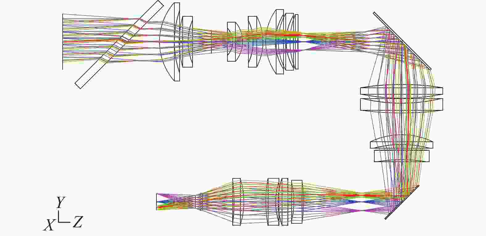
图 4 光学系统结构图
Figure 4. Structure of the optical systems


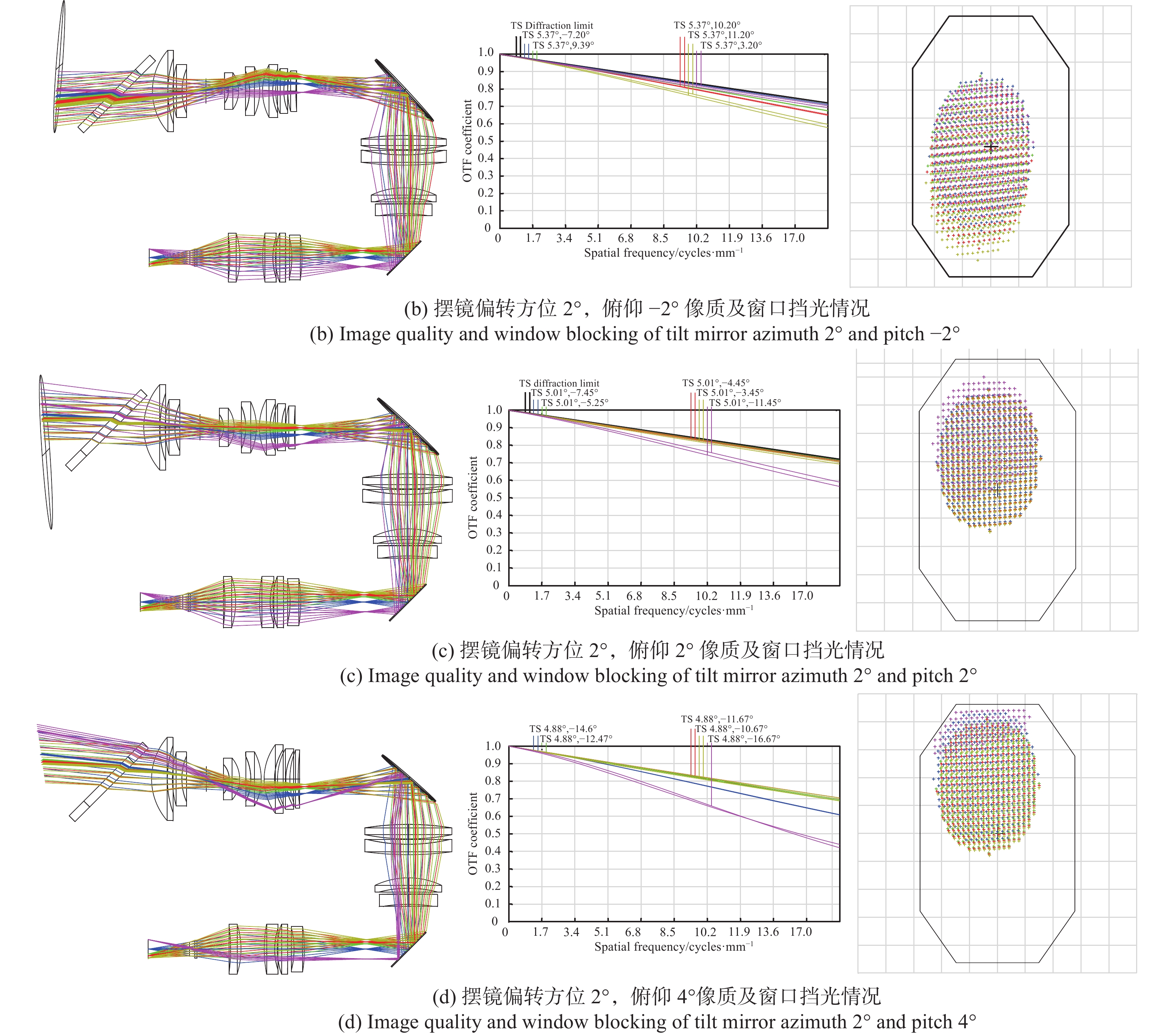
图 5 各视场成像质量及窗口挡光情况
Figure 5. Image quality and window blocking of each field of view
折转后系统总长216 mm,相比物方扫描,扫描镜尺寸较小,且较小的摆动幅度就可以使视场产生较大变化。表2为摆镜偏转角度与光轴指向、成像质量和窗口通光率的关系。根据表2设计结果,扫描镜方位偏转2°、俯仰偏转2°就可使视场产生方位5°、俯仰7.5°变化。根据窗口位置处的光斑尺寸和窗口挡光情况,可以分析在不同摆扫角度下各个瞬时视场的挡光情况,从而计算各视场的能量利用率,最优化设计窗口。
表 2 不同摆镜偏转角下系统性能
Table 2. Performance of the system under different tilt angles
Tilt mirror angle Optical axis direction MTF (17 lp/mm) Window pass ratio Azimuth 2°, pitch -4° Azimuth 4.9°, pitch -14.7° 0.4 85.74% Azimuth 2°, pitch -2° Azimuth 5.02°, pitch -7.45° 0.58 99.43% Azimuth 2°, pitch 2° Azimuth 5.37°, pitch 7.2° 0.57 98.23% Azimuth 2°, pitch 4° Azimuth 5.61°, pitch 14.43° 0.4 78.64% -
文中通过对摆镜扫描光学系统基本形式的分析,提出了一种基于二维摆镜的像方扫描成像体制。相对于一维摆镜,二维摆镜光轴指向灵活,结构紧凑。但是由于方位俯仰之间相互耦合,二维摆镜对光学系统有独特的影响。计算了二维摆镜摆扫时光轴指向及窗口处的光斑尺寸与形状。最后,设计了带摆镜的二维像方扫描制冷红外光学系统,成像质量良好,窗口尺寸合理。
Design of two-dimensional image space scanning cooled infrared optical system with tilt mirror
-
摘要: 带摆镜的像方扫描光学系统通常只在一维方向扫描成像,当摆镜在二维方向摆扫成像时,摆镜方位俯仰耦合运动带来的对光轴指向、光斑尺寸、成像性能等影响不能忽略。分析了不同的摆镜扫描光学系统的基本形式,并对像方摆镜扫描光学系统二维摆扫带来的影响进行了分析。对内轴为方位、外轴为俯仰的像方摆镜在不同的二维摆扫角度下的入射光轴指向和窗口处光斑尺寸进行了理论计算,提出了二维像方摆镜扫描光学系统设计与分析方法。利用Zemax建立了二维像方摆镜扫描光学系统模型,仿真分析了不同方位俯仰摆扫角度下的成像性能、光轴指向以及窗口挡光情况。在不同方位俯仰角度下,光学系统在17 lp/mm处MTF均大于0.4,窗口极限挡光小于21.4%。Abstract: Image space scanning optical system with tilt mirror usually only scanning imaging in one dimension, when tilt mirror is scanning imaging in two dimension, the effect of the tilt mirror’s coupling motion of azimuth and pitch can not be ignored. The basic forms of scanning optical system with tilt mirror were analyzed, and the influence of two-dimensional motion of the image space scanning optical system with tilt mirrors was analyzed. The incident optical axis direction and the spot size on the optical window at the different two-dimensional scanning angles were calculated. A method of image space two-dimensional scanning optical system with tilt mirror design and analysis were proposed. Building the image space two-dimensional scanning optical system model with Zemax, and the imaging performance, optical axis direction and window blocking at different angle of scanning were simulated and analyzed. Under different azimuth and pitch angles, the MTF of the optical system was greater than 0.4 at 17 lp/mm, and the max window blocking of the window was less than 21.4%.
-
Key words:
- infrared /
- image space scanning /
- two-dimension tilt mirror /
- optical system
-
表 1 光学系统设计参数
Table 1. Design parameters of the optical system
No. Type of surface Thickness/mm Tilt x/(°) Tilt y/(°) 1 Standard 170 2 Coordinate break 0 −41 2 3 Coordinate break 0 −41 2 4 Coordinate break −142.554 90 0 5 Coordinate break 0 45 0 6 Optical window 7 Coordinate break 22 −45 0 8 Object lens 9 Coordinate break 0 −90 0 10 Coordinate break 0 41 −2 11 Coordinate break 0 41 −2 12 Coordinate break 0 −41 2 13 Scanning mirror 14 Coordinate break 0 −41 2 15 Image lens  下载: 导出CSV
表 2 不同摆镜偏转角下系统性能
Table 2. Performance of the system under different tilt angles
Tilt mirror angle Optical axis direction MTF (17 lp/mm) Window pass ratio Azimuth 2°, pitch -4° Azimuth 4.9°, pitch -14.7° 0.4 85.74% Azimuth 2°, pitch -2° Azimuth 5.02°, pitch -7.45° 0.58 99.43% Azimuth 2°, pitch 2° Azimuth 5.37°, pitch 7.2° 0.57 98.23% Azimuth 2°, pitch 4° Azimuth 5.61°, pitch 14.43° 0.4 78.64%
下载: 导出CSV
-
[1] Sun Lulu, Liu Chunhua, Zhang Peng, et al. Infrared optical system design for imaging guidance of image space scanning [J]. Electronics Optics & Control, 2014, 21(2): 65-68. (in Chinese) doi: 10.3969/j.issn.1671-637X.2014.02.015 [2] Lin Sen, Cai Wei, Wei Xiaolin, et al. Design of image space scanning system with tilt mirror for cooled medium wave infrared optical system [J]. Journal of Astronautic Metrology and Measurement, 2017, 37(4): 16-19. (in Chinese) doi: 10.12060/j.issn.1000-7202.2017.04.04 [3] Li Gang, Fan Xuewu, Zou Gangyi, et al. Design of space optical system with double infrared waveband based on image space scanning [J]. Infrared and Laser Engineering, 2014, 43(3): 861-866. (in Chinese) doi: 10.3969/j.issn.1007-2276.2014.03.035 [4] Yang Kejun, Yang Zhen, Zhang Yong, et al. Design of optical system for wide field-of-view imaging with image side scanning technology based on rotary dual-wedge [J]. Flight Control & Detection, 2020, 3(6): 43-56. (in Chinese) [5] 曾钦勇. 光电远程快速探测关键技术研究 [D]. 成都: 电子科技大学, 2018. Zeng Qingyong. Study on the key technology of electro-optical remote fast detection[D]. Chengdu: University of Electronic Science and Technology of China, 2018. (in Chinese) [6] 陈超帅. 红外面阵搜索系统快速扫描成像像移补偿技术研究与实现[D]. 上海: 中国科学院大学(中国科学院上海技术物理研究所), 2018. Chen Chaoshuai. Technology reseach and implenmentation on image motion compensation of infrared array search system by fast scan imaging[D]. Shanghai: University of Chinese Academy of Sciences (Shanghai Institute of Technical Physics, Chinese Academy of Sciences), 2018. (in Chinese) [7] 鲁月林. 静止轨道摆扫成像系统设计及技术研究[D]. 合肥: 中国科学技术大学, 2020. Lu Yuelin. Design and technology reseach of the whisk broom imaging system on geostationary orbit[D]. Hefei: University of Science and Technology of China, 2020. (in Chinese) [8] Yu Yang, Wang Shiyong, Jian Yi, et al. Realization of an optical system based on continuous-scan focal plane array [J]. Infrared and Laser Engineering, 2016, 45(1): 0118002. (in Chinese) doi: 10.3788/irla201645.0118002 [9] Zhao Yan, Li Ruigang, Deng Xianchi, et al. Applied research of image rotator scan in infrared optical system [J]. Opto-Electronic Engineering, 2013, 40(8): 84-88. (in Chinese) [10] Liu Jun, Zhang Xibin, Gao Ming. Design of cold MWIR/LWIR infarared dual-band/dual-field panoramic optical system [J]. Journal of Applied Optics, 2016, 37(3): 84-88. (in Chinese) [11] Zhao Yan, Deng Jian, Yu Dezhi. Design of dual field-of-view optical system in long wave infrared with optical passive athermalization [J]. Infrared and Laser Engineering, 2014, 43(5): 1545-1548. (in Chinese) doi: 10.3969/j.issn.1007-2276.2014.05.035 [12] Qu Rui, Mei Chao, Yang Hongtao, et al. Design of compact high zoom ratio infrared optical system [J]. Infrared and Laser Engineering, 2017, 46(11): 1104002. (in Chinese) doi: 10.3788/IRLA201746.1104002 -

 点击查看大图

图(6) / 表(2)
计量
- 文章访问数: 321
- HTML全文浏览量: 71
- PDF下载量: 75
- 被引次数: 0


