


 下载:
下载:


-
近年来,随着国家航空航天以及工业质量检测的快速发展,实现在三维场景的动态测量变得越来越重要。三维形貌测量技术作为客观描述物体几何形貌信息的一种方法,能够避免人类双眼对物体粗略大概的判断,得到精确量化的三维形貌与物体深度信息。然而,大多数高速摄像机或成像系统只能记录缺乏深度信息的二维图像。这极大地限制了人们感知和理解复杂真实物体的能力。在过去几十年里,受传感器、光学工程和计算机视觉快速发展的推动,三维形貌测量技术在许多领域取得巨大的发展[1-3]。
在众多三维测量方法中,最为常见的结构光三维形貌测量方法即为条纹投影轮廓术[4]。条纹投影轮廓术通过向物体投影经过编码的条纹图,根据记录得到受物体表面调制发生形变的条纹图像计算出物体的相位信息。近年来,随着高速相机以及数字光处理技术的发展,基于条纹投影轮廓术的方法具有更精度高、点云重建效率高以及抗干扰更强等优势,有实现动态场景高速三维测量[5-6]的潜力。然而现有的绝大部分工作仍然集中在对于静态物体的形貌测量上[7-8]。如何以更高速度以及更好精度来获取高速场景中运动物体的信息是目前需要研究的主要问题。
随着计算机硬件性能日益提升以及人工智能技术广泛应用,在图像处理、计算成像等领域深度学习通过其强大的特征表达能力在各个实验测试中都取得了令人瞩目的成绩[9-11]。深度学习通过学习大量数据提取需要的特征信息,甚至能够自动获取一些人类无法想象的组合特征。因此可以通过深度学习的方法来尝试解决传统方法下遇到的一些难题。文中受益于深度学习近年来在计算机视觉领域的成功案例,提出了一种基于学习的光栅图像噪声抑制方法。设计利用了基于U-Net深度学习网络结构,将高速场景下采集的包含噪声的条纹图像输入神经网络。卷积层提取输入图像特征信息后,预测输出对应的相位信息进而最终实现三维重构。通过实验表明,针对高速场景下采集的条纹图像,该方法能良好地抑制其中包含的噪声干扰,并且在相位精度、重构效率等等方面都具有优异的性能。与广泛使用的传统三步相移方法相比,该方法不但很好地抑制了高速场景下采集的条纹图案中携带的噪声,而且还能够一定程度上避免在高速场景中运动波纹的干扰,能够获得更高质量的三维形貌测量效果,是一种实用高效的高速三维形貌测量方法。文中首先回顾了条纹投影三维成像的基本原理,然后为了实现高速场景下高精度的三维成像,构建了基于U-Net的深度学习神经网络。接下来在实验中对比了深度学习方法和传统方法对被测物体分别在静态场景和高速动态场景下的恢复效果。通过分析比较后可以发现,在高速场景下噪声条纹图像的三维形貌恢复方面,文中方法的恢复效果远优于传统三步相移的方法。最后总结了该方法对于高速场景下采集的条纹图像中携带噪声的抑制,以及其对于运动波纹的控制效果。
-
文中通过利用U-Net网络直接从高速场景下采集到的条纹图中来提取被测动态物体的相位信息。由于在高速场景下图像采集的速度快、时间短,因此采集到的条纹图像往往携带着严重的噪声干扰。
作为文中深度学习网络的输入,拍摄得到的条纹噪声图像可表示为:
$$ I({a}^{c},{b}^{c})\text=A({a}^{c},{b}^{c})\text+B({a}^{c},{b}^{c})\text{cos}\left[\varphi \right({a}^{c},{b}^{c}\left)\right] $$ (1) 式中:$ I $为被相机记录的条纹噪声图像;$ ({a}^{c},{b}^{c}) $为高速相机的像素坐标;$ A({a}^{c},{b}^{c}) $为平均光强图;$ B({a}^{c},{b}^{c}) $为振幅强度图;$ \varphi ({a}^{c},{b}^{c}) $为待测物体的绝对相位图。可以通过最小二乘法[12]将公式(1)中待测物体的包裹相位表示为:
$$ {\varphi \left({a}^{c},{b}^{c}\right) = \mathit{\rm arctan}\dfrac{M\left({a}^{c},{b}^{c}\right)}{D\left({a}^{c},{b}^{c}\right)} = \text{arctan}\dfrac{\rho B({a}^{c},{b}^{c})\mathit{\rm sin}(\varphi \left({a}^{c},{b}^{c}\right)}{\rho B\left({a}^{c},{b}^{c}\right)\mathit{\rm cos}(\varphi \left({a}^{c},{b}^{c}\right)}}$$ (2) 公式(2)将待测物体的包裹相位转化为一个反正切函数,其中$ M\left({a}^{c},{b}^{c}\right) $和$ D\left({a}^{c},{b}^{c}\right) $分别代表着反正切函数中的分子项与分母项,$ \;\rho $代表一个相位解包裹相关的常数。
由于反正切函数的特性,得到的包裹相位的数值范围为$ [-\pi ,\pi ] $,并且有着$ \text{2}\pi $的不连续跳变。实际上在深度学习的过程中,运用U-Net网络来输出被测物体相位的分子项与分母项替代直接预测输出物体的相位信息。这样做的好处是可以绕开再现$ \text{2}\pi $突变的困难,进而使网络能够预测输出高质量的相位。在网络中得到分子和分母项结合反正切函数后可以得到被测物体的包裹相位,为了进一步得到绝对相位,需要通过相位展开算法将得到的包裹相位进行一个“解包裹”的过程,将其转换为绝对相位$ \varPhi ({a}^{c},{b}^{c}) $来获得连续分布的相位信息。关于被测物体绝对相位和包裹相位的关系可表示为:
$$ \varPhi ({a}^{c},{b}^{c})\text=\varphi ({a}^{c},{b}^{c})\text{+ 2}\pi k({a}^{c},{b}^{c}) $$ (3) 式中:$ \varPhi ({a}^{c},{b}^{c}) $为物体的绝对相位;${k}({a}^{c},{b}^{c})$为条纹级次。
多频时间相位法[13]通过投影多种不同频率的条纹图像到被测物体来进行相位展开。为了提高高速下采集条纹噪声图的效率,投影了基频和高频两个不同频率的光栅图案。由于高频光栅的空间频率对于三维重构结果的精度影响较大,因此为了获得更好的效果,在投影时需要尽可能地提升高频光栅的空间频率。
通过投影仪投影不同频率的条纹图像到待测物体表面,高速相机同步采集得到条纹图,然后通过计算得出高频包裹相位$ {\varphi }_{h}({a}^{c},{b}^{c}) $和低频包裹相位$ {\varphi }_{l}({a}^{c},{b}^{c}) $ [14]。可以结合公式(3)将其表达为:
$$ \varPhi \left( {{a^c},{b^c}} \right){\rm{ = }}\varphi \left( {{a^c},{b^c}} \right){\rm{ + 2}}\pi round\left[ {\frac{{{\varphi _l}\left( {{a^c},{b^c}} \right){f_h}/{f_l} - {\varphi _h}\left( {{a^c},{b^c}} \right)}}{{2\pi }}} \right]{\rm{}} $$ (4) 式中:$ round\left[\right] $为取整函数;$ {f}_{h} $和$ {f}_{l} $分别为高频和低频条纹的条纹频率。所以在已知光栅条纹级次和包裹相位的情况下,就可以计算得到与物体包裹相位相对应的绝对相位。
-
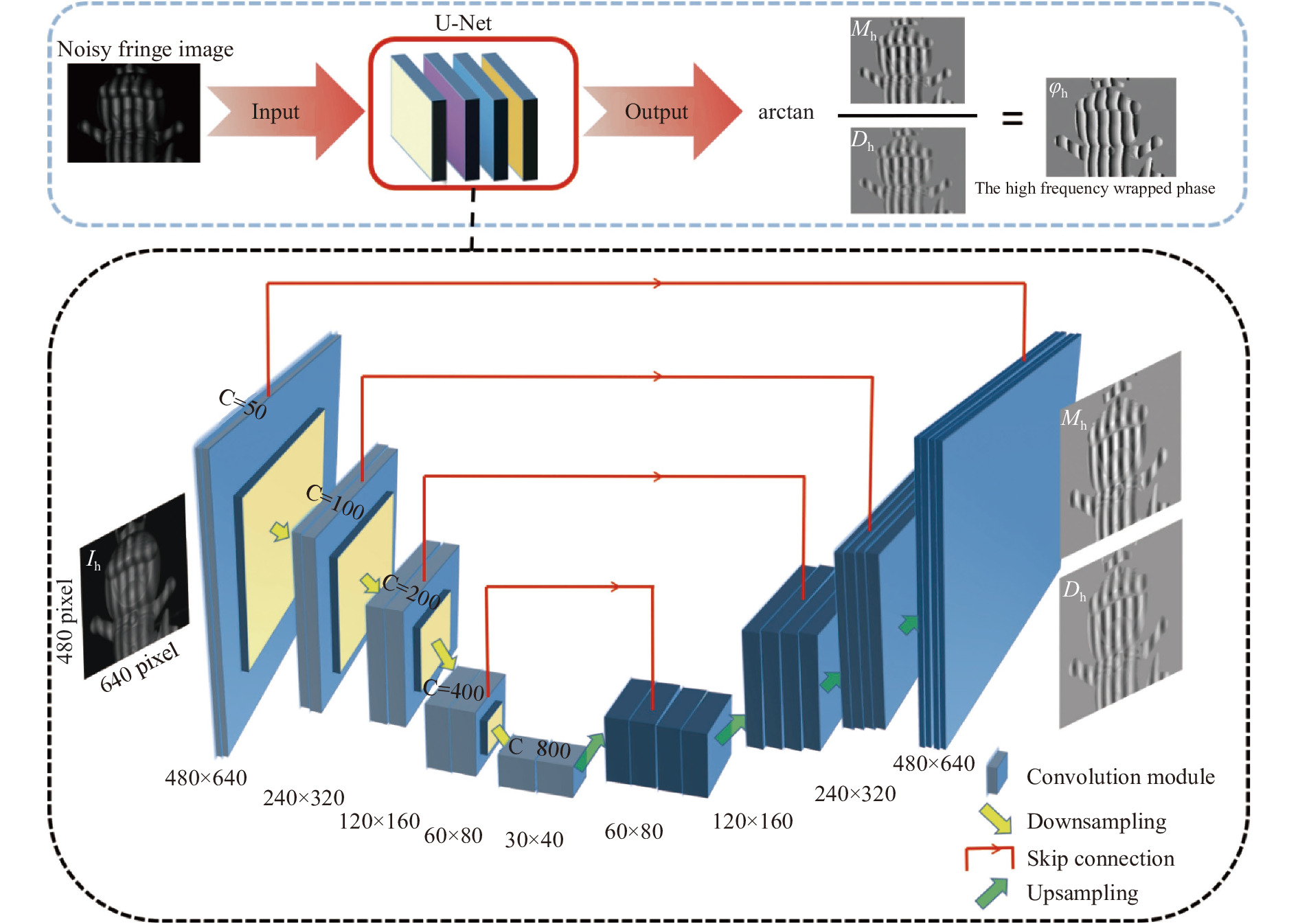
如图1所示,构造了一个基于U-Net网络的深度学习流程图来模拟从高速下采集的条纹噪声图像到U-Net网络的输入图像$ I({a}^{c},{b}^{c}) $,再从输入U-Net网络到得到物体的高质量绝对相位$ \varPhi ({a}^{c},{b}^{c}) $的一系列流程。为了给U-Net网络建立一个高质量的标准的学习对象,通过把标准12步相移算法得到的结果作为标签值。通过对各类不同场景、不同形状的大量相互独立的样本进行训练后,神经网络学习了各类型条纹噪声图像中与相位相关特征的提取。最终即可借助神经网络实现从输入噪声条纹图像到输出高质量对应相位的全过程。可以看到整个流程没有借助任何复杂的预处理和辅助算法,就可以实现对于输入条纹噪声图像稳定地相位展开。

图 1 基于U-Net的噪声条纹图相位获取流程图
Figure 1. The flowchart of noisy fringe image phase acquisition based on U-NET
图1下方展示了文中所用的U-Net网络的内部结构示意图。网络的输入是尺寸大小为$ 640\times 480 $ pixel的高速下的噪声条纹图像。在经过卷积处理后,第一个卷积层输出尺寸大小为$ 640\times 480 $且特征通道数C为50的特征图像。接着进行一次下采样后得到尺寸大小为$ 320\times 240 $且特征通道数C为100的特征图像,同时每一层的特征图像通过跳跃连接的方式与其对应层级解码阶段的图像结合。接着重复之前的过程,得到长宽大小都为原输入条纹噪声图像十六分之一的特征图像来更好地提取浅层特征信息。可以通过这样的过程建立由输入噪声条纹图像到对应分子分母输出的更加精确的映射。因此可以更好地衡量输入噪声条纹图像的相似度,所以可以得到更好的效果。接着特征图像通过上采样来提取一些深层次的特征信息,同时每次上采样后特征图像扩大为长宽大小都为之前2倍的图像。除此以外,可以看到每个上采样层级的通道数都是对应下采样层次2倍。对应层级通过中间的跳跃连接来结合提取的浅层以及深层特征,更好地进行预测。经过四次重复后,最终输出原始图像尺寸大小的对应的预测结果,即为对应的输入噪声条纹图像的反正切函数的分子和分母。
为了避免的相位跃迁,将相机拍摄得到的高速下的高频噪声条纹图像作为深度学习网络的输入后,没有让其来预测与之直接对应的包裹相位。而是将其巧妙转化为预测对应的反正切函数的分子和分母。然后通过反正切函数的分子和分母就可以得到物体的高频包裹相位$ {\varphi }_{h}({a}^{c},{b}^{c}) $,最后通过公式(4)中所示结合对应的低频包裹相位$ {\varphi }_{l}({a}^{c},{b}^{c}) $恢复出物体的绝对相位$\varPhi ({a}^{c},{b}^{c})$。得到了高精度的绝对相位后,就可以结合整个系统的标定参数进行最后的三维重建来恢复出被测物体的形貌。
-
为了验证文中提出方法,搭建了一个双目条纹投影系统来进行此次实验。系统由一个通用仪器公司的投影仪(DLP4500 pro)和两个basler高速相机($ 640\times 480 $分辨率)共同组成。在实验光栅条纹的选择方面,由于高频光栅的空间频率对于三维重构结果的精度影响较大,在投影时一般需要尽可能地提升高频光栅的空间频率,但是过高频率的光栅不利于基频光栅精确的展开。因此为了体现该方法对于高速场景中噪声的良好抑制效果、实现精确的相位展开,最终选择了条纹频率为1的基频光栅条纹图像和条纹频率为24的高频光栅条纹图像。实验过程中,首先使用投影仪以700帧的速度投影24个周期的三步相移条纹到被测物体上,同时投影仪触发basler高速相机在700帧的速度下进行同步采集。本轮在高速场景下采集得到的数据集将作为神经网络的输入。与此同时,对应在正常投影速度(30帧)下同步basler相机采集同一姿态下物体的十二步相移条纹图像来作为网络的训练标签数据集。为了使神经网络具有更好的泛化性能,采集了500组不同场景下不同姿态的对应数据集,它们由一批不同形状、不同材质和不同颜色的物体排列组合旋转而成。每组数据集的输入数据包含三张在高速下采集的三步相移噪声条纹图像,每组的标签数据集则是通过在正常速度下采集的十二步相移解出的分子和分母组成。神经网络使用TensorFlow架构,在英伟达GTX泰坦显卡上进行迭代训练后,深度学习网路训练完成。
-
为了训练深度学习网络对于未出现过静态下的场景的有效性,从数据集中选出了30组高速下的噪声条纹图作为此次实验的测试集数据。这30组静态场景下拍摄的数据在整个深度学习网络的训练过程中从未出现过。通过将这30组测试集数据输入训练完成的深度学习网络,直接得到了对应噪声条纹图像的反正切函数的分子和分母。图2展示了其中两个不同的静态场景被测物体在高速下采集的条纹噪声图像在恢复过程中的不同阶段。其中第一行表示两个场景中采集到的包含噪声的条纹图像,第二与第三行则是通过深度学习网络获得的对应噪声条纹图像的分子和分母,最后一行则是最终想要得到的绝对相位图。由此可以看出图2(a)所示的静态场景中,独立的玩偶猫的整体表面较为平滑圆润。相较于图2(a),在图2(b)中表面相对复杂的人脸雕塑与玩偶猫共同组成了一个复杂的组合场景。因此可以更加客观地来评估深度学习网络对于静态场景下的整体的性能效果。

图 2 高频条纹噪声图像恢复过程中的不同阶段。(a) 玩具猫的高频噪声条纹图像;(b) 组合物体的高频噪声条纹图像;(c) 玩具猫的反正切函数分子;(d) 组合物体的反正切函数分子;(e) 玩具猫的反正切函数分母;(f) 组合物体的反正切函数分母;(g) 玩具猫的绝对相位;(h) 组合物体的绝对相位
Figure 2. Different stages of high-frequency noisy fringe images restoration. (a) High-frequency noisy fringe image of the doll cat; (b) High-frequency noisy fringe image of the combined object; (c) The arc tangent function numerator of the doll cat; (d) The arc tangent function numerator of the combined object; (e) The arc tangent function denominator of the doll cat; (f) The arc tangent function denominator of the combined object; (g) The absolute phase of the doll cat; (h) The absolute phase of the combined object
为了直观地看到笔者课题组的网络对于静态场景下的条纹噪声图输出所恢复的相位精度效果,使用传统三步相移的相位精度效果与其对比。再使用十二步相移法解出的绝对相位作为基准,将传统三步相移和深度学习方法下恢复得到的相位减去真实值。最后将处理分析的数据绘制成了如图3所示的误差图像。其中第一行即为图2中第一列的玩偶猫噪声条纹图像数据分析后得出的结果。图3(a)为传统三步相移法解出的绝对相位与基准值的误差,图3(b)显示了深度学习方法恢复出的绝对相位与基准值的误差,图3(c)则表示这两种方法恢复的结果的第93行数据在全局上与基准值的误差分布,其中红色的线代表三步相移在全局上与真实值的误差,蓝色的线代表深度学习的恢复值在全局上与真实值的误差。可以比较容易发现的是无论是传统的三步相移的方法,还是深度学习的方法,在玩偶猫的整个表面都存在着由于噪声干扰所引起的误差。其中比较平滑连续的地方相对边缘颜色较浅,与基准值更加接近。但是对于玩偶猫的嘴部深度信息变化比较剧烈的地方,以及玩偶猫不连续的边缘处,则与基准值存在着一定的误差。
相比于传统的方法,深度学习的方法明显与基准值更接近,在对噪声的抑制上做得更好。总体来说,深度学习的方法整体恢复的效果还是比较优异的。在图3(c)中也可以看出,深度学习恢复的相位偏差在全局上被传统的三步相移法包围着,与基准值更加接近。
为了研究基于U-Net网络的深度学习对于静态下的存在组合物体的复杂场景的恢复性能,对图2中具有代表性的组合物体的高速噪声条纹图分析得到了图3中第二行的结果。可以看到面形为复杂的牛顿石雕和面形相对平滑的塑料玩偶猫共同组成了一个复杂的静态场景,它们没有直接相连,并且石雕的位置相对靠后一些。从图3(d)、(e)和(f)中可以直观地发现,对于存在组合物体的复杂场景,深度学习方法依旧有着对噪声不错的抑制性能。同时对比同为恢复的结果中选取的第93行数据的对应误差曲线图3(c)和图3(f),可以发现对于复杂场景下的组合物体无论是传统的三步相移还是深度学习的方法,恢复误差都要大于独立物体的场景。总体来说,深度学习的方法大大控制了高速下采集的高频条纹图像中的噪声干扰,对于相位的恢复效果明显优于传统三步相移方法,展现出了它在测量高速场景下静态的不连续物体以及物体的复杂区域的优异性能。

图 3 深度学习方法与传统方法的相位误差对比。(a) 传统三步相移方法下恢复的玩偶猫的绝对相位与真实值误差;(b) 深度学习方法下恢复的玩偶猫的绝对相位与真实值误差;(c) 两种方法下恢复的玩偶猫的绝对相位与真实值的误差曲线图;(d) 传统三步相移方法下恢复的组合物体的绝对相位与真实值误差;(e) 深度学习方法下恢复的组合物体的绝对相位与真实值误差;(f) 两种方法下恢复的组合物体的绝对相位与真实值的误差曲线图
Figure 3. Comparison of the phase error between deep learning and traditional method. (a) The error between the true value and the absolute phase of the doll cat recovered by the traditional three-step phase shift method; (b) The error between the true value and the absolute phase of the doll cat using deep learning; (c) The error curve of the true value and the absolute phase of the doll cat recovered by the two methods; (d) The error between the true value and the absolute phase of the combined object recovered by the traditional three-step phase shift method; (e) The error between the true value and the absolute phase of combined objects using deep learning; (f) The error curve of the true value and the absolute phase of the combined object recovered by the two methods
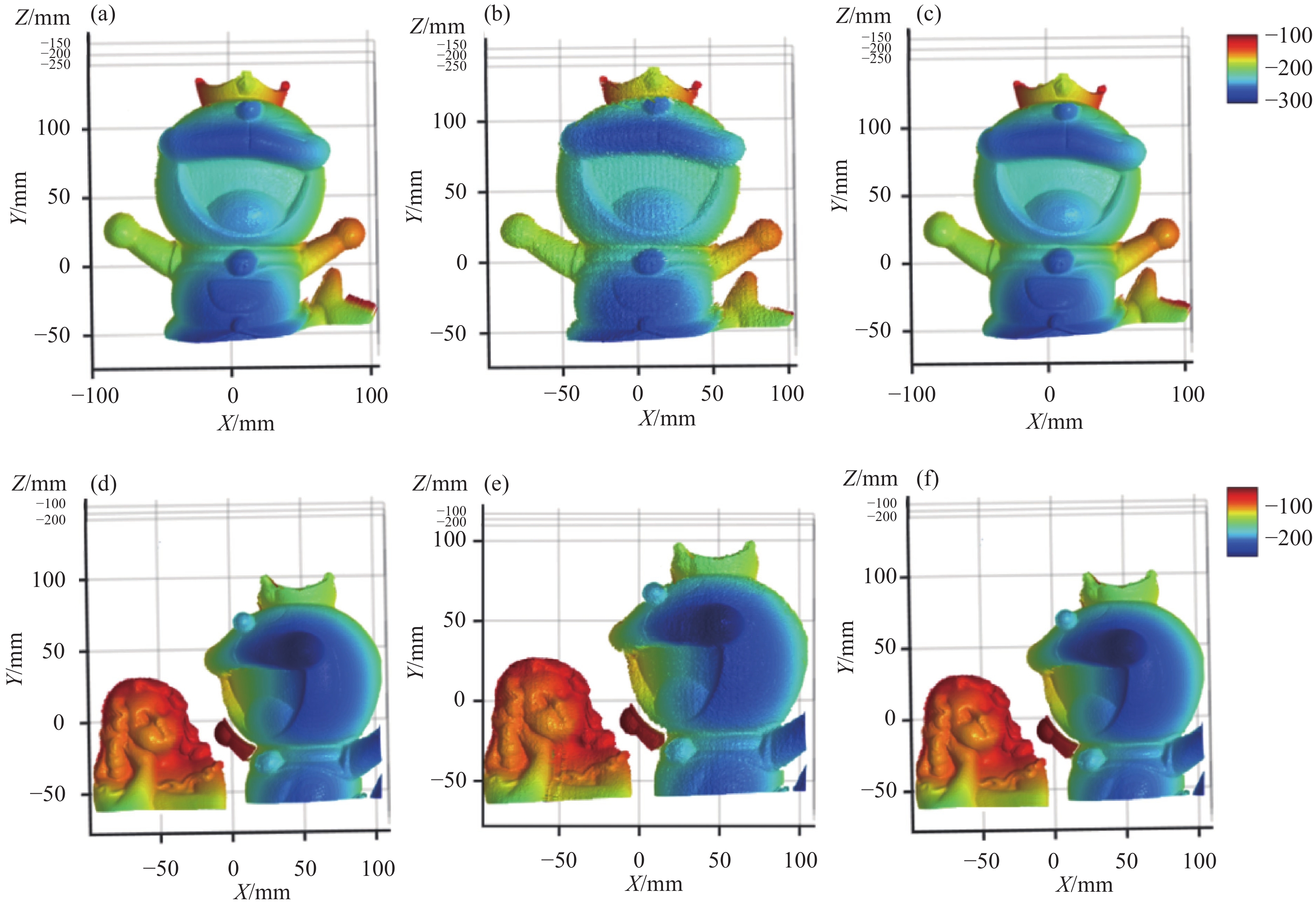
最后,为了对比传统三步相位恢复的三维效果和文中的基于学习的光栅图像噪声抑制的方法恢复的效果。用两种不同的方法恢复出了图2所示的两组数据的三维形貌。其中图4(a)和图4(d)分别代表通过文中方法恢复出的玩具猫及组合场景的三维形貌,图4(b)和图4(e)则为传统三步相移方法恢复的三维结果,而图4(c)和图4(f)则分别对应了通过标准十二步相移恢复的真值。
可以直观地看到处于中间的图4(b)和图4(e)的表面相比于真值的纹理比较粗糙,存在着明显的误差导致的起伏,恢复结果不是很理想。反观图4(a)和图4(d)文中方法下的恢复效果,表面平滑且几乎没有不平整的区域,与真值很接近。因此可以看出文中基于学习的光栅图像噪声抑制的方法对于高速下采集的条纹图像所含有噪声有很好的抑制效果,具有优异的三维形貌恢复性能。

图 4 不同方法下恢复三维效果对比。 (a) 文中方法恢复的玩偶猫的三维重构结果;(b) 传统方法下恢复的玩偶猫的三维重构结果;(c) 玩偶猫的真实三维重构结果;(d) 文中方法下恢复的组合物体的三维重构结果;(e) 传统方法下恢复的组合物体的三维重构结果;(f) 组合物体的真实三维重构结果
Figure 4. Comparison of 3D reconstruction results under different methods. (a) 3D reconstruction result of the doll cat restored by the method in this paper; (b) 3D reconstruction result of dolls cat restored by traditional methods; (c) The true 3D reconstruction result of the doll cat; (d) 3D reconstruction result of composite objects recovered by the method in this paper; (e) 3D reconstruction result of composite objects recovered by traditional methods; (f) The true 3D reconstruction result of the combined object
-
为了验证文中提出的方法对动态场景下高速运动物体的三维成像效果。对一个高速旋转的小电风扇进行了测量。小电风扇可以通过按键调整其输入的电流来控制转速由一档速度(约800 rpm)切换为二档速度(约1800 rpm)。由于投影仪(DLP4500 pro)对于标准的正弦条纹的投影速度无法满足本轮实验的高速场景的要求,而其对于二值图像[15-16]的投影速率则高达4 000帧。因此在本轮实验过程中选用了二值条纹来满足投影仪投影速度正确地触发高速相机进行同步采集。在实验过程中,在700帧/s下分别对旋转风扇的一档速度和二档速度投影二值条纹拍摄得到了动态的旋转风扇条纹噪声图像。
图5(a)以及图5(d)分别展示了分别在一档速下和二档速下旋转的风扇的高频条纹噪声图像。在700帧/s的高速下对旋转的风扇投影了三步相移的条纹图,高速相机同步采集这一动态场景。可以很容易看到在一个相移周期里,小电风扇的同一扇叶与其对应的第一幅图片中扇叶的初始位置的白色基准线的距离在逐步增大。当风扇的速度达到二档速下,距离的增大幅度更加明显。

图 5 不同速度下风扇三维重构结果对比。(a)一档速(约800 rpm)下采集的风扇图像;(b)传统三步相移法一档速下风扇三维重构结果;(c) 基于U-Net网络一档速下风扇三维重构结果;(d)二档速(约1800 rpm)下采集的风扇图像; (e)传统三步相移法二档速下风扇三维重构结果;(f) 基于U-Net网络二档速下风扇三维重构结果
Figure 5. 3D reconstruction results comparison of fans at different speeds. (a) Fan images collected at first speed (about 800 rpm); (b) 3D reconstruction results of fan at first speed by the traditional three-step phase shift method; (c) 3D reconstruction results of fan at first speed based on U-Net network; (d) Fan images collected at second speed (about 1800 rpm); (e) 3D reconstruction results of fan at second speed with the traditional three-step phase shift method; (f) 3D reconstruction results of fan at second speed based on U-Net network
在一档速的高速图像下方的图5(b)和图5(c)是对于该速度下小电风扇的三维重构的结果。其中图5(b)为传统三步相移方法恢复出来的效果,而图5(c)为基于深度学习网络训练后的恢复的效果。从这两幅图中对应的相邻局部放大效果图来看,传统方法对于以一档速度旋转的小风扇的三维恢复效果比较差,其受噪声影响较为严重。在图5(c)中框选的放大区域可以发现深度学习的方法恢复的区域相对更加平滑、起伏变化不大。较传统方法相比更加接近真实的恢复效果,三维重构结果受噪声干扰小。图5(d)为二档速度下采集到的风扇旋转图像。对比图5(a)可以明显看出电风扇的同一扇叶与对应扇叶初始位置的基准线的距离变化幅度要大一点。为了研究传统方法和文中的方法针对更快的动态场景下的恢复性能,笔者再次对达到二档速度下拍摄的风扇数据进行了三维重构。通过图5(e),可以非常直观的发现传统方法二档速下风扇的重构结果由图像的采集速度相对变慢,受到噪声和运动的干扰增强,甚至产生了运动的波纹[17]。相对应的图5(f)所示的基于U-Net网络深度学习的方式,由于其通过数据驱动的方式来直接预测得到的相位信息,对噪声的抑制效果明显,不会受到运动速度带来的干扰。因此图5(f)中基于U-Net网络二档速下的风扇三维重构结果很明显更好一些。
通过实验发现,文中基于深度学习的方法在动态场景下依旧具有相当不错的性能。尤其当被测物体运动速度增大时,基于深度学习的方法可以消除运动带来的干扰、抑制环境噪声,与传统的方法在恢复效果上拉开明显的差距。
-
为了使文中提出的基于学习的光栅图像噪声抑制方法的三维测量的精度有一个定量的结果分析。对两个标准的陶瓷精度球进行了实验测试分析。两个陶瓷球的半径分别为25.398 mm和25.40 mm,两球之间球心距为100.069 mm。通过文中的方法获得精度球的相位数据,进而获得其三维数据并进行三维重构。两个精度球的三维重构结果如图6(a)和图6(d)所示。通过将获得的精度球三维数据与球面拟合的参考数据进行比较后,获得了如图6(b)和图6(e)所示的陶瓷球测量的误差值分布图,陶瓷球的误差直方图分布则如图6(c)和图6(f)所示。经过计算可得两个陶瓷球的均方根误差(RMS)分别为50.919 $\; \text{μ}{\rm{m}} $和51.882 $\; \text{μ}{\rm{m}} $。通过对标准的陶瓷球的精度分析实验结果可以表明,该实验可以实现测量精度约为52 $ \;\text{μ}{\rm{m}} $的三维形貌测量。

图 6 精度球三维重构及其分析。(a)左边精度球三维重构结果;(b)左边精度球误差分布;(c)左边精度球误差直方图;(d)右边精度球三维重构结果;(e)右边精度球误差分布;(f)右边精度球误差直方图
Figure 6. 3D reconstruction and analysis of precision sphere. (a) 3D reconstruction result of left precision sphere; (b) Error distribution of left precision sphere; (c) Error histogram of left precision sphere; (d) 3D reconstruction result of right precision sphere; (e) Error distribution of right precision sphere; (f) Error histogram of right precision sphere
-
在此次工作中,笔者课题组提出了基于学习的光栅图像噪声抑制方法。与绝大多数基于结构光的快速三维测量方法不同[18-19],基于深度学习的方法在构建完成神经网络、经过适当训练后,可以避免传统方法中繁杂的准备工作,直接输入高速噪声条纹图来得到对应的反正切函数的分子分母。借助于人工智能的帮助,该方法在静态场景中恢复相位的精度上有着不小的优势。实验结果表明,基于学习的光栅图像噪声抑制方法可以在相机帧率高达700帧/s的场景下实现对运动物体的高精度三维测量,对于高速测量场景中存在的噪声干扰具有优异的抑制效果,部分场景下的精度甚至可以与高精度的十二步相移法十分接近。更进一步,针对离线的快速运动场景三维测量,相比于传统的相移法,该方法由于仅使用一幅图像,不仅克服了噪声的干扰,且对物体运动不敏感,有利于恢复高质量的运动物体三维轮廓,具有良好的实用性和恢复性能。
A learning based on approach for noise reduction with raster images
-
摘要: 基于条纹投影的三维形貌测量广泛应用于工业制造、质量检测、生物医疗、航空航天等领域。然而在高速测量的场景下,由于光栅图像的采集过程曝光时间短,三维重建结果通常会受到较为严重的图像噪声干扰。近年来,深度学习技术在计算机视觉等领域得到了广泛应用,并且取得了巨大的成功。受此启发,提出了一种基于学习的光栅图像噪声抑制方法。首先构建了一个基于U-net的卷积神经网络。其次在训练过程中,构建的神经网络学习从含有噪声的条纹图像到对应高质量包裹相位之间的映射关系。当经过适当训练,该网络可从含有噪声的条纹图像中准确恢复相位信息。实验结果表明:针对离线的快速运动场景三维测量,该方法仅利用一幅光栅图像可恢复高精度的相位信息,且相位精度优于传统的三步相移方法。该方法可为提升运动高速场景三维测量的精度提供切实可靠的解决方案。Abstract: Three-dimensional (3D) shape measurement based on fringe projection was widely used in industrial manufacturing, quality testing, biomedicine, aerospace and other fields. However, due to the short exposure time of raster images acquisition process, 3D reconstruction results were usually affected by serious image noise in the scene of high-speed measurement. In recent years, deep learning has been widely used in computer vision and other fields, and has achieved great success. Inspired by this, we proposed a learning based approach for noise reduction with raster images. Firstly, we constructed a convolutional neural network based on U-NET. Secondly, the neural network was constructed to learn the mapping relationship between the noisy fringe images and the corresponding high quality wrapped phase during the training process. With proper training, this network can accurately recovered phase information from noisy fringe images. Aiming at off-line 3D measurement in fast moving scene, experimental results show that the proposed method can recover high-precision phase information by using only one raster image, and the phase accuracy is better than the traditional three-step phase shift method. This method can provide a practical and reliable solution for improving the accuracy of 3D measurement in high-speed scene.
-
Key words:
- high-speed 3D shape measurement /
- noisy fringe images /
- deep learning /
- phase recovery
-
图 1 基于U-Net的噪声条纹图相位获取流程图
Figure 1. The flowchart of noisy fringe image phase acquisition based on U-NET
图 2 高频条纹噪声图像恢复过程中的不同阶段。(a) 玩具猫的高频噪声条纹图像;(b) 组合物体的高频噪声条纹图像;(c) 玩具猫的反正切函数分子;(d) 组合物体的反正切函数分子;(e) 玩具猫的反正切函数分母;(f) 组合物体的反正切函数分母;(g) 玩具猫的绝对相位;(h) 组合物体的绝对相位
Figure 2. Different stages of high-frequency noisy fringe images restoration. (a) High-frequency noisy fringe image of the doll cat; (b) High-frequency noisy fringe image of the combined object; (c) The arc tangent function numerator of the doll cat; (d) The arc tangent function numerator of the combined object; (e) The arc tangent function denominator of the doll cat; (f) The arc tangent function denominator of the combined object; (g) The absolute phase of the doll cat; (h) The absolute phase of the combined object
图 3 深度学习方法与传统方法的相位误差对比。(a) 传统三步相移方法下恢复的玩偶猫的绝对相位与真实值误差;(b) 深度学习方法下恢复的玩偶猫的绝对相位与真实值误差;(c) 两种方法下恢复的玩偶猫的绝对相位与真实值的误差曲线图;(d) 传统三步相移方法下恢复的组合物体的绝对相位与真实值误差;(e) 深度学习方法下恢复的组合物体的绝对相位与真实值误差;(f) 两种方法下恢复的组合物体的绝对相位与真实值的误差曲线图
Figure 3. Comparison of the phase error between deep learning and traditional method. (a) The error between the true value and the absolute phase of the doll cat recovered by the traditional three-step phase shift method; (b) The error between the true value and the absolute phase of the doll cat using deep learning; (c) The error curve of the true value and the absolute phase of the doll cat recovered by the two methods; (d) The error between the true value and the absolute phase of the combined object recovered by the traditional three-step phase shift method; (e) The error between the true value and the absolute phase of combined objects using deep learning; (f) The error curve of the true value and the absolute phase of the combined object recovered by the two methods
图 4 不同方法下恢复三维效果对比。 (a) 文中方法恢复的玩偶猫的三维重构结果;(b) 传统方法下恢复的玩偶猫的三维重构结果;(c) 玩偶猫的真实三维重构结果;(d) 文中方法下恢复的组合物体的三维重构结果;(e) 传统方法下恢复的组合物体的三维重构结果;(f) 组合物体的真实三维重构结果
Figure 4. Comparison of 3D reconstruction results under different methods. (a) 3D reconstruction result of the doll cat restored by the method in this paper; (b) 3D reconstruction result of dolls cat restored by traditional methods; (c) The true 3D reconstruction result of the doll cat; (d) 3D reconstruction result of composite objects recovered by the method in this paper; (e) 3D reconstruction result of composite objects recovered by traditional methods; (f) The true 3D reconstruction result of the combined object
图 5 不同速度下风扇三维重构结果对比。(a)一档速(约800 rpm)下采集的风扇图像;(b)传统三步相移法一档速下风扇三维重构结果;(c) 基于U-Net网络一档速下风扇三维重构结果;(d)二档速(约1800 rpm)下采集的风扇图像; (e)传统三步相移法二档速下风扇三维重构结果;(f) 基于U-Net网络二档速下风扇三维重构结果
Figure 5. 3D reconstruction results comparison of fans at different speeds. (a) Fan images collected at first speed (about 800 rpm); (b) 3D reconstruction results of fan at first speed by the traditional three-step phase shift method; (c) 3D reconstruction results of fan at first speed based on U-Net network; (d) Fan images collected at second speed (about 1800 rpm); (e) 3D reconstruction results of fan at second speed with the traditional three-step phase shift method; (f) 3D reconstruction results of fan at second speed based on U-Net network
图 6 精度球三维重构及其分析。(a)左边精度球三维重构结果;(b)左边精度球误差分布;(c)左边精度球误差直方图;(d)右边精度球三维重构结果;(e)右边精度球误差分布;(f)右边精度球误差直方图
Figure 6. 3D reconstruction and analysis of precision sphere. (a) 3D reconstruction result of left precision sphere; (b) Error distribution of left precision sphere; (c) Error histogram of left precision sphere; (d) 3D reconstruction result of right precision sphere; (e) Error distribution of right precision sphere; (f) Error histogram of right precision sphere
-
[1] Gorthi S S, Rastogi P. Fringe projection techniques: Whither we are? [J]. Optics and Lasers in Engineering, 2010, 48: 133-140. [2] Feng S, Chen Q, Gu G, et al. Fringe pattern analysis using deep learning [J]. Advanced Photonics, 2019, 1(2): 025001. [3] Qian K. Two-dimensional windowed Fourier transform for fringe pattern analysis: Principles, applications and implementations [J]. Optics and Lasers in Engineering, 2007, 45(2): 304-317. [4] Xu J, Zhang S. Status, challenges, and future perspectives of fringe projection profilometry [J]. Optics and Lasers in Engineering, 2020, 135: 106193. doi: 10.1016/j.optlaseng.2020.106193 [5] Zhang S. High-speed 3 D shape measurement with structured light methods: A review [J]. Optics and Lasers in Engineering, 2018, 106: 119-131. [6] Feng S, Zuo C, Yin W, et al. Micro deep learning profilometry for high-speed 3 D surface imaging [J]. Optics and Lasers in Engineering, 2019, 121: 416-427. doi: 10.1016/j.optlaseng.2019.04.020 [7] Ma G Q, Liu L, Yu Z L, et al. Application and development of three-dimensional profile measurement for large and complex surface [J]. Chinese Optics, 2019, 12(2): 214-228. (in Chinese) doi: 10.3788/co.20191202.0214 [8] Zhang Q, Wang Q, Hou Z, et al. Three-dimensional shape measurement for an underwater object based on two-dimensional grating pattern projection [J]. Optics& Laser Technology, 2011, 43(4): 801-805. [9] Yin W, Chen Q, Feng S, et al. Temporal phase unwrapping using deep learning [J]. Scientific Reports, 2019, 9(1): 20175. doi: 10.1038/s41598-019-56222-3 [10] Feng S, Zuo C, Yin W, et al. Application of deep learning technology to fringe projection 3 D imaging [J]. Infrared and Laser Engineering, 2020, 49(3): 0303018. (in Chinese) doi: 10.3788/irla.35_2020-12by [11] Zhong J X, Feng S, Yin W, et al. Speckle projection profilometry with deep learning [J]. Infrared and Laser Engineering, 2020, 49(6): 20200011. (in Chinese) doi: 10.3788/irla.8_2020-0011 [12] Malacara D. Optical Shop Testing[M]. New York: John Wiley & Sons, 2007: 59. [13] Zuo C, Huang L, Zhang M, et al. Temporal phase unwrapping algorithms for fringe projection profilometry: A comparative review [J]. Optics and Lasers in Engineering, 2016, 85: 84-103. doi: 10.1016/j.optlaseng.2016.04.022 [14] Zuo C, Feng S, Huang L, et al. Phase shifting algorithms for fringe projection profilometry: A review [J]. Optics and Lasers in Engineering, 2018, 109: 23-59. doi: 10.1016/j.optlaseng.2018.04.019 [15] Lohry W, Zhang S. High-speed absolute three-dimensional shape measurement using three binary dithered patterns [J]. Optics Express, 2014, 22 (22): 26752-26762. [16] Wu Z, Guo W, Zhang Q. High-speed three-dimensional shape measurement based on shifting Gray-code light [J]. Optics Express, 2019, 27(16): 22631-22644. doi: 10.1364/OE.27.022631 [17] Feng S, Zuo C, Tao T, et al. Robust dynamic 3-D measurements with motion-compensated phase-shifting profilometry [J]. Optics and Lasers in Engineering, 2018, 103: 127-138. doi: 10.1016/j.optlaseng.2017.12.001 [18] Zhang H, Zhang Q, Li Y, et al. High-speed 3 D shape measurement with temporal Fourier transform profilometry [J]. Applied Sciences, 2019, 9(19): 4123. doi: 10.3390/app9194123 [19] Wang L Z, Wang Y, Liang J, et al. Measurement of full-field strain incell phone dropping test by high-speed 3 D digital image correlation method [J]. Optics and Precision Engineering, 2018, 26(9): 2174-2180. (in Chinese) doi: 10.3788/OPE.20182609.2174 -

 点击查看大图
计量
- 文章访问数: 464
- HTML全文浏览量: 173
- PDF下载量: 78
- 被引次数: 0

