


 下载:
下载:


-
转轴是机床的关键运动部件,其几何运动误差严重影响机床的加工精度。目前提高机床加工精度的重要方法是通过对运动误差测量后建立误差补偿模型进行补偿[1-2]。根据ISO230-1国际标准,径向运动误差是机床转轴运动的重要误差项之一。其测量方法包括利用精密圆光栅的衍射法[3]、激光位移传感器法[4],激光准直法[5-6]和一些需要解耦计算的间接测量方法[7-10]等。干涉测量法凭借非接触、易集成、精度可溯源的优势,成为精密测量领域最有前景的测量方法[11-13]。笔者课题组提出将激光干涉与伺服跟踪相结合的转轴径向运动误差测量方法,具有易于集成和无需解耦的优势,在保证干涉信号连续的同时,实现转轴360°径向运动误差的全周测量[14]。
在对转轴径向运动误差进行激光干涉测量时,需要对信号的非线性误差进行修正以保证相位解算的精度,其中对信号峰谷值的提取至关重要。基于伪极值法的峰谷值提取可以改善由于激光功率漂移造成的极值求解偏差,但其算法基于排数法替换原来的伪极值,仅适用于匀速运动或频率固定的振动测量[15]。对于转轴的径向运动误差测量,由于待测转轴和伺服转轴还存在转速不匀和伺服延迟等问题,干涉信号相位存在持续微幅抖动且抖动位置随机、幅度不均匀,使得传统峰谷值提取算法失效,非线性修正的效果不理想。
鉴于此,文中提出一种零值截取-阈值判定的干涉信号处理方法。对转轴径向运动误差的实测干涉信号的处理结果表明,该方法能够显著提高干涉信号的非线性误差修正精度,从而保证相位的精确解算,最终实现转轴径向运动误差的高精度干涉测量。
-
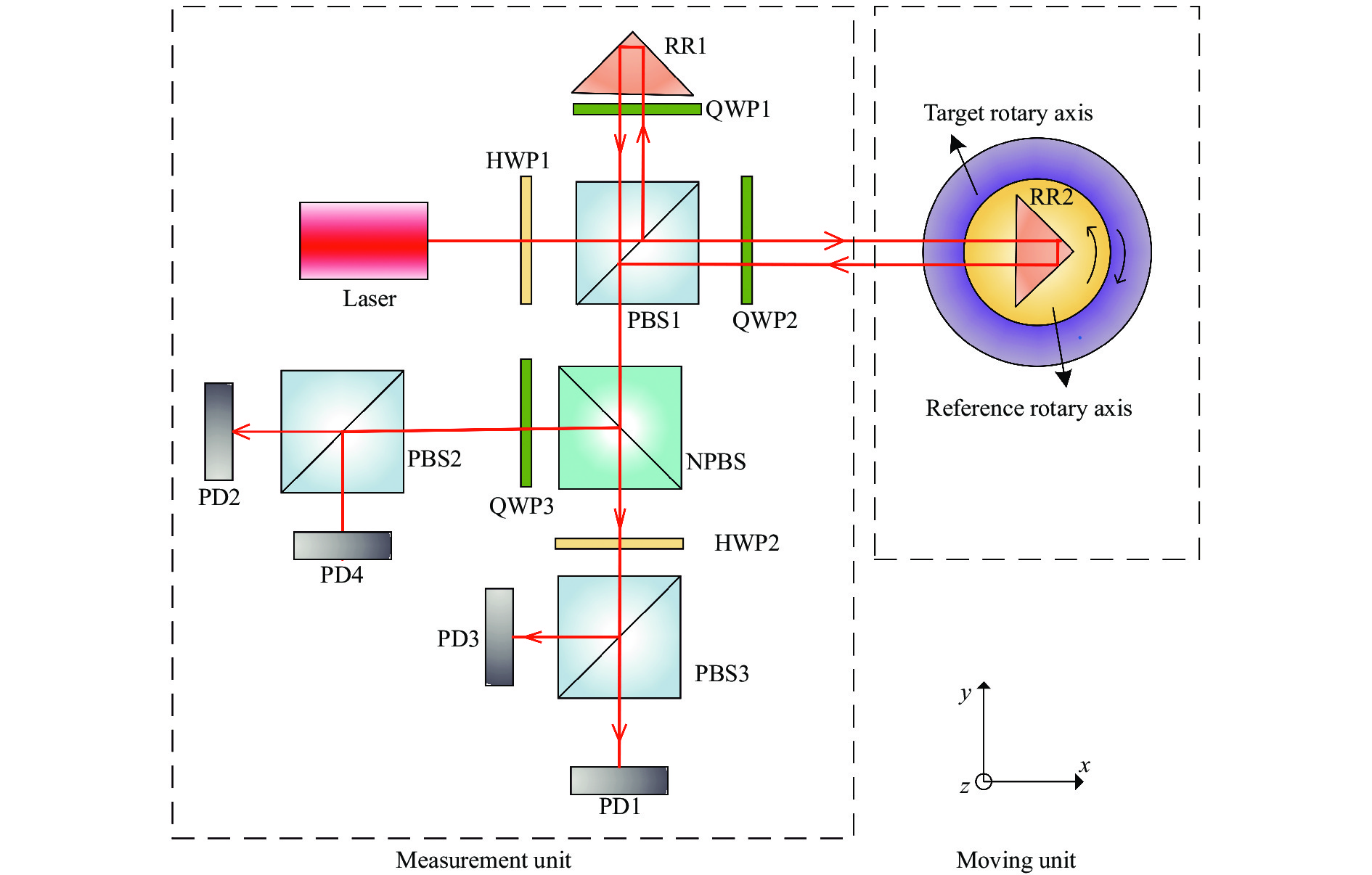
激光干涉测量转轴径向运动误差的原理如图1所示,主要包括测量单元和移动单元两部分,其中测量单元包含单频激光器和偏振分光棱镜等光电器件,移动单元包含伺服转轴和角锥棱镜等。

图 1 转轴径向运动误差测量原理图
Figure 1. Schematic diagram of measuring the radial motion error of an axis
激光干涉的测量臂与待测转轴径向运动误差方向平行,伺服转轴同轴安装于待测转轴上方,角锥棱镜安装于伺服转轴上方。伺服转轴相对于待测转轴反向旋转,从而保证入射至角锥棱镜的激光光线始终能够返回测量单元,并与参考臂返回的激光光线在偏振分光棱镜PBS1处汇合之后经非偏振分光棱镜NPBS等光学器件在四个光电探测器上产生四路相位依次相差90°的干涉信号,如图2(a)所示。然后将相位相差180°的两路信号分别进行电路差分,消除共模噪声,得到一组包含相位和位移方向信息的正交信号,如图2(b)所示。

图 2 干涉信号示意图
Figure 2. Schematic diagram of interference signals
设待测转轴的径向运动误差为δx,则在干涉测量的两臂之间产生的光程差为2δx,干涉信号的周期变化次数N为:
$$ N = \dfrac{{{\text{2}}{\delta _x}}}{\lambda } = \dfrac{\varphi }{{{\text{2}}\pi }} $$ (1) 式中:λ为空气中激光的中心波长;φ为干涉信号的总相位变化值。可见,要实现转轴径向运动误差的高精度测量,需要对干涉信号的相位值进行高精度解算。
-
激光干涉测量是以微米量级的激光波长为测量基准,为了进一步达到纳米级的测量精度,要对干涉信号进行相位细分。CORDIC算法通过角度旋转迭代对相位信号进行反正切计算,如图3所示,该算法收敛速度快、精度高,且避免了复杂的乘除、开方等运算,适用于嵌入式处理系统。

图 3 CORDIC算法原理
Figure 3. Principle of the CORDIC algorithm
CORDIC算法迭代公式为:
$$ \left\{ {\begin{array}{*{20}{c}} {{x_{i + 1}} = {x_i} - {d_i}({2^{ - i}}{y_i})} \\ {{y_{i + 1}} = {y_i} - {d_i}({2^{ - i}}{x_i})} \\ {z{}_{i + 1} = {z_i} - {d_i}{\theta _i}} \end{array}} \right. $$ (2) 式中:i=0,1,···,n;θi=arctan (2−i);令z0=0,zn即为所求相位;di为方向判断因子,取值±1。由于计算相位的过程是有限旋转迭代,必然导致计算结果θ与真值θ0之间存在残余角度误差Δθ:
$$ \Delta \theta = {\theta _0} - \theta = {\theta _0} - \displaystyle\sum\limits_{i = 0}^n {{\theta _i}} $$ (3) 可见,迭代次数n越大,残余角度误差越小。针对任意两个时刻之间的一段干涉信号相位解算,为了保证精度并减少运算量,文中研究提出将CORDIC算法仅用于首尾不足1/8周期的信号相位处理,得到高精度的首尾相位小数计数值n1和n2,而对中间段的信号则采用八细分算法。八细分算法是通过比较正交信号函数值的符号和绝对值将一个周期均匀分成8部分,如图4所示,只需较低的运算量即可实现信号1/8周期整数的计数N1/8。

图 4 信号整数部分细分原理
Figure 4. Sub-division principle for the integer part of signal
因此,信号的整体波形细分计数原理如图5所示。根据公式(1),转轴径向运动误差可表示为:
$$ {\delta _x} = \dfrac{\lambda }{2}N = \dfrac{\lambda }{2}\left( {\dfrac{{{N_{{1 \mathord{\left/ {\vphantom {1 8}} \right. } 8}}}}}{8} + {n_1} + {n_2}} \right) $$ (4) 综合考虑计算量和测量分辨率的要求,CORDIC算法迭代次数选择10,对应理论分辨率约为0.97 nm。

图 5 波形计数原理示意图
Figure 5. Principle diagram of waveform counting
-
正交干涉信号的质量是影响上述相位细分算法精确性和稳定性的重要因素。然而,由于光源不稳定性、光电器件自身特性不理想以及环境参数变化等原因,正交干涉信号不可避免的存在非线性误差,包括直流偏差p、q,交流幅值不等Ax、Ay和非正交误差α,以上简称三差。因此,实际正交干涉信号可表示为:
$$ \left\{ {\begin{array}{*{20}{c}} {{U_y} = {A_y}{\text{sin(}}\theta {\text{)}} + p } \\ {{U_x} = {A_x}{\text{cos(}}\theta + \alpha {\text{)}} + q} \end{array}} \right. $$ (5) 通过准确求解正交信号的峰谷值可以对直流偏差和交流幅值不等误差进行修正,具体如公式(6)和(7):
$$ \left\{ {\begin{array}{*{20}{c}} {{A_y} = \dfrac{{\text{1}}}{{\text{2}}}\left( {{U_{y\_\max}} + {U_{y\_\min}}} \right)} \\ {{A_x} = \dfrac{{\text{1}}}{{\text{2}}}\left( {{U_{x\_\max}} + {U_{x\_\min}}} \right)} \end{array}} \right. $$ (6) $$ \left\{ {\begin{array}{*{20}{c}} {p = \dfrac{1}{2}\left( {{U_{y\_\max }} + {U_{y\_\min }}} \right)} \\ {q = \dfrac{1}{2}\left( {{U_{x\_\max }} + {U_{x\_\min }}} \right)} \end{array}} \right. $$ (7) 式中:Uy_max和Ux_max为两信号的峰值;Uy_min和Ux_min为两信号的谷值。
对非正交误差的修正可通过矢量运算的形式将两信号转化为相位一致的信号,从而无需解算非正交误差,即可完成修正。公式(8)中,U1和U2是消除直流偏差和幅值不等误差后的两信号,β为修正后产生的新相位。非正交误差的修正将使两信号再次出现幅值不等,需要重新归一化处理。
$$ \left\{\begin{array}{l} U_y{ }^{\prime}=U_1+U_2=A \cdot \sqrt{2+2 \cos \alpha} \cdot \sin (\theta+\beta) \\ U_x^{\prime}=U_1-U_2=A \cdot[-\sqrt{2+2 \cos \alpha} \cdot \sin (\theta+\beta)] \end{array}\right. $$ (8) 由上述修正原理可知,信号峰谷值的准确求解是三差信息提取和非线性误差修正的前提和关键。然而,由于伺服转轴和待测转轴的自身转速不匀、伺服响应延迟或跟踪不稳等原因,实验发现转轴径向运动误差的干涉测量信号中存在大量随机微幅抖动,传统的信号峰谷值提取方法准确度差,三差信息提取存在较大偏差,无法实现非线性误差的有效修正。
图6所示为信号相位抖动的仿真示意图。传统方法利用信号零点或极值点位置进行信号截取并提取峰谷值,仅适用于图6中第3段所示的不含相位抖动的信号,而针对第1和第2段包含位置与幅度随机抖动的转轴径向运动误差干涉测量信号不能适用。特别是当相位抖动位于极值点或零点位置附近,单凭零点或极值点截取信号会将抖动识别为一个修正周期,造成峰谷值提取错误。此外,将极值点作为修正周期截取的标准,会增大硬件电路运算压力。

图 6 相位抖动仿真信号
Figure 6. Simulation signals of phase jitter
文中提出零值截取-阈值判定的新方法,采用自适应窗进行取样,将三次有效零点位置作为一个修正周期截取标准,再配合阈值判定,可以准确提取峰谷值,且运算量小。具体如下:
以蓝色正弦信号为例(以任意一只正交信号中的零值点位置作为周期划分标准不影响修正效果),信号经过三次零点为初始取样长度,将该信号段内峰值、谷值与设定阈值进行比较。若峰值和谷值均超过阈值,说明该信号段包含了有效的三差信息;未超过阈值,则说明相位在持续抖动,需要扩大截取范围,寻找下一个零值点,直至信号段内峰谷值超过设定阈值。阈值的设定与激光功率、光电探测器响应以及后续信号放大倍率相关,与被测轴无关,考虑激光功率存在零漂,可将阈值设定为理论峰谷值的0.8倍左右。
图6截取信号段a-b-c,零值点b、c处有明显的相位抖动,实际信号并未达到谷值位置,此时峰谷值有一项未超过阈值,需要扩大信号段截取范围,当信号截取范围扩大至a-b-c-d-e,此时,峰谷值均超过阈值,该信号段为包含准确峰谷值的有效修正周期。将此时的峰谷值带入三差修正算法,能够实现非线性误差的有效修正。
-
按图1所示的测量原理搭建了转轴径向运动误差干涉测量实验装置,如图7所示。待测转轴和参考转轴都为Aerotech公司生产,型号为ANT95-360-R,其标称径向运动误差重复性数值小于1 μm,由于两轴精度近似,需同时考虑两轴的精度。以30°为测量间隔进行全周测量,设定转速为0.57 (°)/s,实验室环境温度为(22±1) ℃。
对实测信号的处理结果如下(以某一段实测信号为例):从实测干涉信号中截取一个总步长为一个二分之一波长、方向为反向的信号段,对应公式(4)中N=−8,经过FIR低通滤波后如图8(a)所示,虚线l1、l2、l3和l4表示以三次零点作为周期划分标准将信号分为四部分,Ry0为正弦信号的两阈值差。由正交信号的特点可知,任意一只信号的数值未到峰谷值就反向可视为相位反向特征。反向意味着相位倒退,如信号段s-q即为p-s的反向过程,因此,p-q段信号对应步长变化量为0。基于此,线l1~l4之间的信号段对应步长变化量相当于0。当信号反向发生在转轴连续转动的信号中段(非首尾),反向相位会自动向前补偿。因此,若抖动幅度小于八细分长度,则不影响计数结果。

图 7 实验装置图
Figure 7. The experimental devices

图 8 原始信号与非线性修正结果
Figure 8. Original signals and results of nonlinear correction
截取时,第一部分中两信号峰谷值均超过阈值。而后面三部分中峰-峰值Ry2、Ry3和Ry4明显小于Ry0,说明信号在连续反、正向交替,这时的极值点位置并非有效的峰谷值信息,传统方法修正后的结果如图8(b)所示,虚线框内信号出现跳变,将造成波形计数错误。如图8(c)所示,文中方法修正后的信号连续不跳变。图9给出了对此段信号的八细分区间划分过程,可见,在虚线框内传统方法产生了明显划分错误。经传统方法修正后的信号波形计数结果为N=−9.32,文中方法的计数结果为N=−8.03,解算精度提高了97.7%。
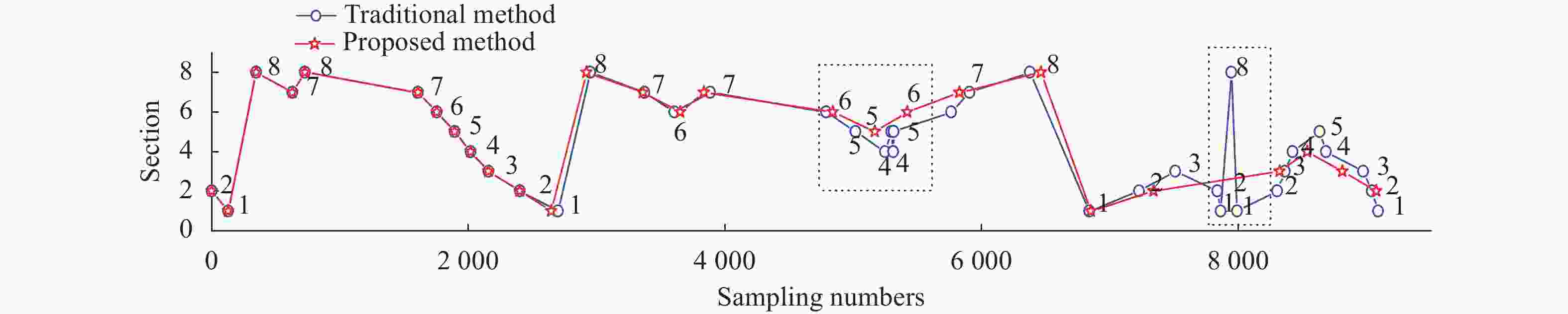
图 9 算法处理后的八细分区间值对比
Figure 9. Comparison of results by the eight-sub division algorithm
-
对转轴径向运动误差进行了5次重复性全周测量,以全周13个测量点中的最大值作为测量重复性数值(两轴的安装存在偏心误差和轴线不平行误差,二者对转轴径向运动误差测量结果产生一阶三角函数形式的影响,其幅值远大于待测量,可通过函数拟合的形式予以消除)。数据处理结果表明,测量重复性数值由传统方法的4.752 μm减小至文中方法的0.206 μm,小于两轴标称数值之和2 μm。
为了进一步证明文中方法的有效性,以德国SIOS生产的激光干涉仪(型号:MI5000)作为标准仪器进行对比实验。对比误差如图10所示。在同一角度位置,测量装置与标准仪器的测量平均值的差值为该角度位置的对比误差。结果表明,相比于传统方法,文中方法对转轴径向运动误差干涉测量信号的解算结果与标准仪器的最大对比误差由3.5 μm降为2.0 μm。
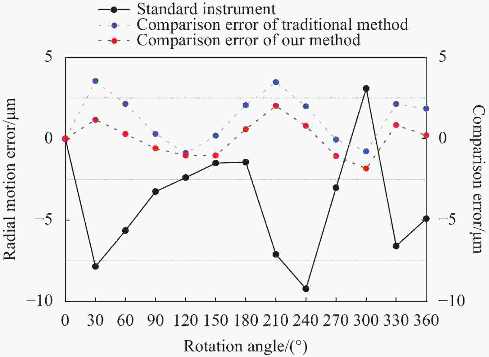
图 10 误差对比
Figure 10. Result of comparison error
-
针对转轴径向运动误差干涉测量信号的相位抖动问题,提出了一种零值截取-阈值判定的信号处理新方法,成功克服了相位抖动对非线性误差修正过程中对峰谷值提取的影响,提高了信号相位解算精度。在实验中搭建了转轴径向运动误差的干涉测量装置,对转轴径向运动误差进行重复性实验,数据表明,其重复性数值相比传统处理方法的4.75 μm减小到0.21 μm。在对比实验中,与标准仪器的最大对比误差由3.5 μm降为2.0 μm,验证了方法的有效性。此外,文中提出的算法对其它相对运动的干涉测量信号处理也具有一定的参考价值。
Signal processing method for measuring the radial motion error of rotary axis by interferometry
-
摘要: 转轴径向运动误差是转轴的重要误差项之一,严重影响数控机床等转轴相关设备的精度和性能。利用激光干涉配合伺服转轴可以实现转轴径向运动误差的测量,但由于待测转轴和伺服转轴的自身转速不匀、伺服响应延迟、跟踪不稳等原因,干涉测量信号存在持续微幅相位抖动,进而造成非线性误差难以有效修正,相位解算精度不高,测量误差大。针对这一问题,提出一种零值截取-阈值判定的干涉信号处理方法,成功消除了相位抖动的影响。设计并搭建了一套转轴径向运动误差的激光干涉测量装置,针对实测信号的处理结果表明,相比于传统修正方法,文中提出的修正方法使得转轴径向运动误差干涉测量信号解算的重复性由4.8 μm减小到0.2 μm,与标准仪器的对比误差由3.5 μm降为2 μm。Abstract: The radial motion error is one of the most important errors of rotary axis, which seriously affects the precision and performance of CNC machine tools. Using laser interference with reference rotary axis can achieve measurement of radial motion error. Neither target or reference rotary axis is ideal, there are some restrictions like uneven speed, response delay and unstable tracking. These restrictions cause phase jitter and make the non-linear correction difficult. It will affect the phase calculation accuracy of the interference signal. In order to eliminate the influence of phase jitters, a type of signal processing method is proposed. The paper designs and builds a set of laser interference measuring device for measuring the radial motion error. Compared to the traditional correction method, the proposed method reduces the measurement repeatability from 4.8 μm to 0.2 μm, and the error compared with the standard instrument is decreased from 3.5 μm to 2 μm.
-
Key words:
- rotary axis /
- radial motion error /
- phase jitters /
- on-linear correction
-
图 1 转轴径向运动误差测量原理图
Figure 1. Schematic diagram of measuring the radial motion error of an axis
图 9 算法处理后的八细分区间值对比
Figure 9. Comparison of results by the eight-sub division algorithm
-
[1] Soichi Ibaraki, Wolfgang Knapp. Indirect measurement of volumetric accuracy for three-axis and five-axis machine tools: A review [J]. International Journal of Automation Technology, 2012, 6(2): 110-124. [2] Yang J, Feng Q, Li J. Review on multi-degree-of-freedom motion error measurement methods for rotary-axis laser [J]. Laser & Optoelectronics Progress, 2016, 53(9): 090003. (in Chinese) [3] Lou Z, Hao X, Liu L, et al. spindle radial motion error measurement using a circular grating and a autocollimator [J]. Optics and Precision ngineering, 2019, 27(9): 2053-2061. (in Chinese) doi: 10.3788/OPE.20192709.2053 [4] Huang B. Research on the spindle radial motion error of the numerical machine tools based on laser displacement sensor[D]. Hangzhou: Zhejiang University, 2008. (in Chinese) [5] Sun C. Research on multi-degree-of-freedom measurement method for precision engineering[D]. Changchun: University of Chinese Academy of Sciences (Changchun Institute of Optics), 2021. (in Chinese) [6] Lv Y, Feng Q, Liu L, et al. Six-degree-of-freedom measurement method based on multiple collimated beams [J]. Infrared and laser Engineering, 2014, 43(11): 3597-3602. (in Chinese) [7] Liang R, Li W, Wang Z, et al. A method to decouple the geometric errors for rotary axis in a five-axis CNC machine [J]. Measurement Science and Technology, 2020, 31(8): 085007. doi: 10.1088/1361-6501/ab7ded [8] Li Q, Wang W, Zhang J, et al. All position-dependent geometric error identification for rotary axes of five-axis machine tool using double ball bar [J]. The International Journal of Advanced Manufacturing Technology, 2020, 110(5): 1351-1366. [9] Li F, Dong H, Wang J, et al. Error analysis of rotation positioning accuracy measured by laser tracker [J]. Mechanical and Electrical Equipment, 2021, 38(3): 59-63. (in Chinese) [10] Bringmann B, Besuchet J P, Rohr L. Systematic evaluation of calibration methods [J]. CIRP Annals, 2008, 57(1): 529-532. doi: 10.1016/j.cirp.2008.03.114 [11] Xia H, Hu M, Zhang X. High precision of quadrature signals for homodyne interferometer [J]. Optics and Precision Engineering, 2017, 25(9): 2309-2316. (in Chinese) doi: 10.3788/OPE.20172509.2309 [12] Li L. Application of laser interferometer in XY table measurement [J]. Equipment for Electronic Products Manufacturing, 2020, 49(5): 37-41. (in Chinese) [13] Ping S, Fu Y, Zhang F, et al. Study on measurement method of mirror reflection laser tracking interferometric length measurement [J]. Infrared and Laser Engineering, 2021, 50(12): 20210624. (in Chinese) doi: 10.3788/IRLA20210624 [14] Li J, Feng Q, Bao C, et al. Method for simultaneously and directly measuring all six-DOF motion errors of a rotary axis [J]. Chinese Optics Letters, 2019, 17(1): 47-51. [15] Xing J, Zhao G. Research on compensation of laser interferometry [J]. Laser Journal, 2020, 41(7): 63-66. (in Chinese) -

 点击查看大图
图(10)
计量
- 文章访问数: 147
- HTML全文浏览量: 30
- PDF下载量: 41
- 被引次数: 0


