


-
近年来,随着SWaP-C(Size, Weight, Power and Cost)概念从红外探测器拓展到红外热像仪整机设计全过程,轻小型、低功耗、低成本、高性能红外热像仪是全球红外热像仪生产厂家的一致追求[1]。在非制冷红外热像仪方面,相对已模块化的非制冷探测器[2]及成像电路,光学系统在减轻产品质量、缩小体积尺寸、降低成本价格方面发挥重要作用,成为降低整机SWaP-C特征的主要因素。
设计轻小型、低成本、高性能的非制冷红外光学系统需要考虑以下几个方面:一是透镜数量少,较少的透镜数量直接降低光学系统成本及透镜质量;二是光学系统总长短,紧凑的光学系统减少结构包络体积及壳体质量;三是大物镜直径小,与制冷型红外光学系统采用二次成像压缩大物镜直径不同,非制冷红外光学系统一般采用一次成像方式,大物镜直径比系统入瞳直径大。大物镜直径小能够降低零件成本、缩小热像仪横向尺寸及减轻系统质量;四是较高的光学调制传递函数(MTF),MTF高可充分利用器件的空间频率使得整机系统的探测、识别、确认(DRI)距离最大化;五是环境适应性好,一般非制冷光学相对孔径大,系统焦深小,且常用红外材料在高低温变化过程中折射率变化大[3],影响系统成像质量,需要实现消热设计。
目前,在非制冷长波红外连续变焦光学领域已有较多的研究成果。参考文献[4]采用二次成像技术压缩大物镜口径,利用复合变焦技术,基于320×240@25 μm探测器实现系统F#1.6、焦距9~324 mm的36倍连续变焦光学设计,该设计使用九个透镜,系统总长较长,伺服控制复杂;参考文献[5]采用两运动组元的正组补偿技术,基于640×512@17 μm探测器实现六片透镜焦距20~120 mm的六倍连续变焦光学设计;参考文献[6]采用正组补偿技术,基于1024×768@14 μm探测器实现五片透镜焦距25~75 mm、F#为1.2的三倍连续变焦光学设计。上述文献光学系统侧重于大倍率、高性能、大靶面等方面,一般都采用了五片以上透镜,系统远摄比较大,且都缺少高低温环境下的像质分析,限制了红外热像仪的使用范围。文中引入三组联动变焦技术平衡像差及压缩系统总长,采用变F#设计技术约束系统大物镜直径,通过主动补偿的无热化技术实现系统在高低温情况下成像清晰,构建四片透镜架构的非制冷长波红外连续变焦光学系统,该系统具有总长短、成本低、环境适应性好、性能高等特点,能在手持侦察设备或无人系统平台中得到广泛应用,满足日益增长的市场需求。
-
三组联动连续变焦系统是通过三个透镜组在轴向连续移动改变光学系统组合焦距,同时保持像面位置不动并在连续变焦过程中成像质量良好的机械补偿变焦系统。三组联动连续变焦光学系统常见形式是由前固定组、变倍组、补偿组、第二补偿组和后固定组五组透镜组成。通过建立数学模型能快速分析变焦过程,确定变焦系统高斯光学参数[7],得到近轴光学初始架构。三组联动连续变焦系统运动模型如图1所示。
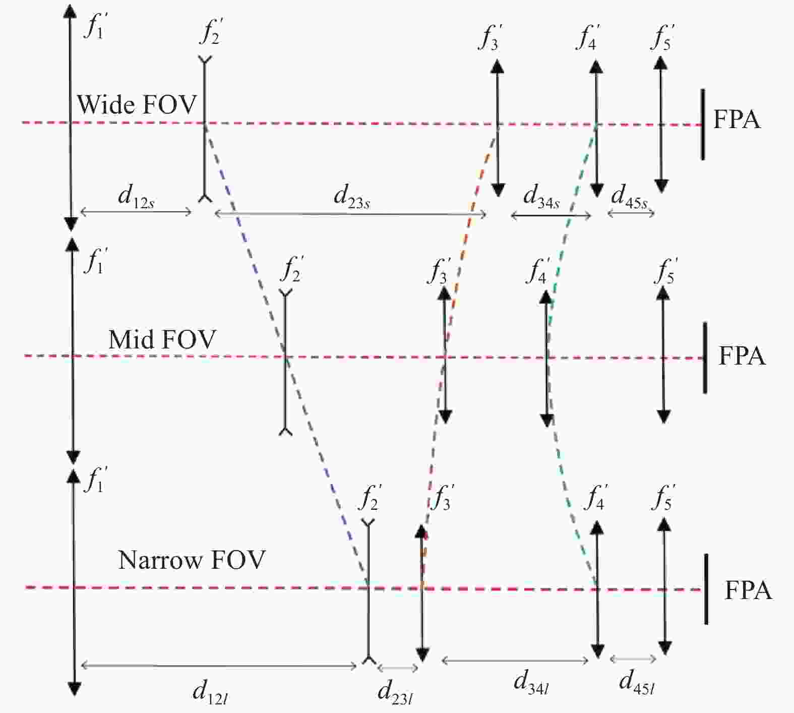
图 1 三组联动连续变焦系统原理图
Figure 1. Principle diagram of continuous zoom optical system with three group linkage
采用微分方程分析变焦核的三个组元—变倍组、补偿组及第二补偿组的运动规律。因变倍组
$ {f}_{2}^{{′}} $ 的移动,引起整个运动组分的像面移动为${\;\beta }_{4}^{2}{\;\beta }_{3}^{2}\left(1-{\;\beta }_{2}^{2}\right){\rm{d}}{q}_{2}$ ,因补偿组$ {f}_{3}{{'}} $ 的移动,引起整个运动组分的像面移动为${\;\beta }_{4}^{2}(1-{\;\beta }_{3}^{2}){\rm{d}}\Delta$ 。第二补偿组$ {f}_{4}' $ 的移动,引起整个运动组分的像面移动为$(1-{\;\beta }_{4}^{2}){\rm{d}}{q}_{4}$ ,为达到像面稳定,3个运动组元像面移动量的代数和必须为零。即:$$ \beta _4^2\beta _3^2(1 - \beta _2^2){\rm{d}}{q_2} + \beta _4^2(1 - \beta _3^2){\rm{d}}\Delta + (1 - \beta _4^2){\rm{d}}{q_4} = 0 $$ (1) 而变倍组
$ {f}_{2}' $ 、补偿组$ {f}_{3}' $ 、第二补偿组$ {f}_{4}' $ 、微分移动量${\rm{d}}{q}_{2}$ 、${\rm{d}}\mathrm{\Delta }$ 、${\rm{d}}{q}_{4}$ 与其倍率变化${\rm{d}}{\beta }_{2}$ 、${\rm{d}}{\beta }_{3}$ 、${\rm{d}}{\beta }_{4}$ 之间的关系为:$$ {\rm{d}}{q}_{2}=\frac{{f}_{2}{{'}}}{{\beta }_{2}^{2}}{\rm{d}}{\beta }_{2} $$ (2) $$ {\rm{d}}{q}_{4}={f}_{4}{{'}}{\rm{d}}{\beta }_{4} $$ (3) $$ {\rm{d}}\Delta =(1-{\beta }_{2}^{2}){\rm{d}}{q}_{2}+\frac{{f}_{3}{{'}}}{{\beta }_{3}^{2}}{\rm{d}}{\beta }_{3} $$ (4) 将公式(2)~(4)代入公式(1),经整理得到3组联动连续变焦微分方程如下:
$$ \frac{{1 - \beta _2^2}}{{\beta _2^2}}f_2^\prime {\rm{d}}{\beta _2} + \frac{{1 - \beta _3^2}}{{\beta _3^2}}f_3^\prime {\rm{d}}{\beta _3} + \frac{{1 - \beta _4^2}}{{\beta _4^2}}f_4^\prime {\rm{d}}{\beta _4} = 0 $$ (5) 公式(5)为多变量全微分型微分方程。设
$ U({\beta }_{2},{\beta }_{3},{\beta }_{4}) $ 为原函数,则有:$$ {\rm{d}}U\left({\beta }_{2},{\beta }_{3},{\beta }_{4}\right)=0 $$ 其通解为:
$$U\left(\beta_2, \beta_3, \beta_4\right)=f_2^{\prime}\left(\frac{1}{\beta_2}+\beta_2\right)+f_3^{\prime}\left(\frac{1}{\beta_3}+\beta_3\right)+f_4^{\prime}\left(\frac{1}{\beta_4}+\beta_4\right)=C$$ (6) 式中:
$ C $ 为常量。设变倍组
$ {f}_{2}{{'}} $ 、补偿组$ {f}_{3}{{'}} $ 、第二补偿组$ {f}_{4}^{{{'}}} $ 初始状态都处于系统长焦位置,则$$ {\beta }_{2}={\beta }_{2l} \text{;} {\beta }_{3}={\beta }_{3l} \text{;} {\beta }_{4}={\beta }_{4l} $$ 得到方程的特解:
$$ \begin{split} & f_2^\prime \left( {\frac{1}{{{\beta _2}}} - \frac{1}{{{\beta _{2l}}}} + {\beta _2} - {\beta _{2l}}} \right) + f_3^\prime \left( {\frac{1}{{{\beta _3}}} - \frac{1}{{{\beta _{3l}}}} + {\beta _3} - {\beta _{3l}}} \right) + \\& f_4^\prime \left( {\frac{1}{{{\beta _4}}} - \frac{1}{{{\beta _{4l}}}} + {\beta _4} - {\beta _{4l}}} \right) = 0 \end{split}$$ (7) 将公式(7)整理得到补偿组
$ {f}_{3}{{{'}}} $ 的倍率$ \;{\beta }_{3} $ 构成的二次方程:$$ {\beta }_{3}^{2}-b{\beta }_{3}+1=0 $$ (8) 其中,系数
$ b $ 为:$$ \begin{split} b= &-\frac{f_2^{\prime}}{f_3^{\prime}}\left(\frac{1}{\beta_2}-\frac{1}{\beta_{2 l}}+\beta_2-\beta_{2 l}\right)-\frac{f_4^{\prime}}{f_3^{\prime}}\left(\frac{1}{\beta_4}-\frac{1}{\beta_{4 l}}+\beta_4-\beta_{4 l}\right) + \\ &\left(\frac{1}{\beta_{3 l}}+\beta_{3 l}\right) \\[-10pt] \end{split} $$ (9) 解得
$ \; {\beta }_{3} $ 的两根为:$$ {\beta }_{31}=\frac{b+\sqrt{{b}^{2}-4}}{2} $$ (10) $$ {\beta }_{32}=\frac{b-\sqrt{{b}^{2}-4}}{2} $$ (11) 系统初始参数求解过程如下。
(a)将公式(2)积分并整理得到变倍组
$ {f}_{2}{{{'}}} $ 的倍率$\; {\beta }_{2} $ :$$ {\beta }_{2}=\dfrac{1}{\dfrac{1}{{\beta }_{2l}}-\dfrac{{q}_{2}}{{f}_{2}^{\text{'}}}} $$ (12) (b)将公式(3)积分并整理得到第二补偿组
$ {f}_{4}{{{'}}} $ 的倍率$\, {\beta }_{4} $ :$$ {\beta }_{4}={\beta }_{4l}-\frac{{q}_{4}}{{f}_{4}{{'}}} $$ (13) (c)根据求得的
$ \; {\beta }_{2} $ 、$\; {\beta }_{4} $ 按照公式(9)求出系数$ b $ ,再由公式(10)、(11)解得补偿组$ {f}_{3}{{{'}}} $ 满足运动方程的两个解$\, {\beta }_{31} $ 和$\, {\beta }_{32} $ ;(d)将公式(4)积分并由补偿组的两个解求出满足补偿像面位移的移动量
${\Delta }_{1}$ 和${\Delta }_{2}$ :$$ {\Delta }_{1}={f}_{3}{{'}}\left( {\frac{1}{{\beta }_{31}}-\frac{1}{{\beta }_{3l}}} \right)-{q}_{2}+{f}_{2}{{'}}\left( {{\beta }_{2}-{\beta }_{2l}} \right) $$ (14) $$ {\Delta }_{2}={f}_{3}^{{'}}\left( { \frac{1}{{\beta }_{32}}-\frac{1}{{\beta }_{3l}}} \right)-{q}_{2}+{f}_{2}^{{'}}({\beta }_{2}-{\beta }_{2l}) $$ (15) (e)求出系统的总变倍比:
$$ {\varGamma }_{1}=\frac{{\beta }_{2l}{\beta }_{3l}{\beta }_{4l}}{{\beta }_{2}{\beta }_{31}{\beta }_{4}} $$ (16) $$ {\varGamma }_{2}=\frac{{\beta }_{2l}{\beta }_{3l}{\beta }_{4l}}{{\beta }_{2}{\beta }_{32}{\beta }_{4}} $$ (17) 根据上述三组联动变焦模型,利用公式(9)~(17),通过编程迭代求出满足指标要求的各组元光焦度分配及光学元件位置间隔。
-
非制冷长波红外连续变焦光学系统设计流程如图2所示。首先,根据三组联动连续变焦模型编制计算程序,依据设计指标从系统总长、光焦度分配、零件间隔等方面优选初始光学架构,建立理想光学模型;其次,根据元件光焦度合理选型选材,设置评价函数进入优化和全局优化;再次,依据评价函数收敛结果评价常温及高低温环境成像质量;然后进入公差分析环节,使得系统达到加工装配要求的容差范围,其中评价函数修改优化、像质评价及公差分析环节反复多次迭代,直至达到设计技术指标要求;最后,开展系统变焦曲线重整化操作,完成系统设计。
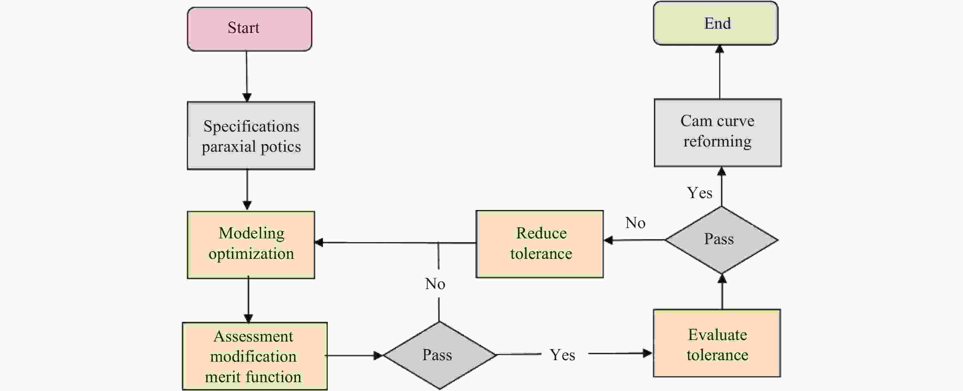
图 2 连续变焦光学系统设计流程图
Figure 2. Flow chart of continuous zoom optical system design
-
根据目前市场主流的640×512@12 μm非制冷氧化钒焦平面探测器,设计了一款紧凑低成本、高透过率、全温度范围使用的非制冷长波红外连续变焦光学系统。系统主要技术指标见表1。
表 1 光学系统技术指标
Table 1. Technical parameters of optical system
Parameter Value Spectral range/μm
Zoom ratio
Field of view/(°)
F#
Focal length/mm
Transmittance
Working temperature/℃8-12
6.0∶1
21×16.8-3.5×2.8
≤1.2
20.7-126
>80%
−40-60 -
按照设计流程,首先根据三组联动连续变焦模型,编制三组联动变焦系统初始参数计算程序。依据光学系统设计指标,求解连续变焦系统高斯光学参数(即元件光焦度、间隔分配)建立近轴光学系统。三组联动连续变焦系统含有五个组元,若要实现四片透镜架构需要减去一个组元,从校正像差难易程度分析,第二补偿组兼具后固定组平衡像差的能力,减去后固定组是合理可行的。
取变倍组
$ {f}_{2}=-1 $ 、补偿组$ {f}_{3}=1.28 $ 、第二补偿组$ {f}_{4}=1.1 $ ;长焦时$\, {\beta }_{2\mathrm{l}}'=-{1.7}^{{x}}$ 、$\, {\beta }_{3\mathrm{l}}'=-0.{8}^{{x}}$ 、$\, {\beta }_{4\mathrm{l}}'=0.6{5}^{{x}}$ 、$ \, {\beta }_{5}=1 $ 短焦时第一二透镜间隔$ {d}_{12\mathrm{s}}=0.4 $ ;第二三透镜间隔$ {d}_{23\mathrm{s}}=2.25 $ ;第三四透镜间隔$ {d}_{34\mathrm{s}}=0.25 $ 。代入初始参数计算程序得到系统各组元光焦度及间隔分配结果。抽取五个焦距位置设置近轴系统其初始间隔分配结果如表2所示。表 2 光学系统间隔初始参数
Table 2. Initial parameters of optical system spacing
Focal length/mm 126 104 80 40 20 f1/f2 spacing/mm 71.2 67.9 61.6 40.7 16.4 f2/f3 spacing/mm 6.3 11.1 19.3 46.4 78.4 f3/f4 spacing/mm 59.9 56.0 52.3 46.5 39.6 Back intercept/mm 5.7 8.1 9.9 9.5 8.7 其次,考虑设置孔径光阑位置。孔径光阑位置对大物镜直径及系统像差平衡有显著影响。经分析,将孔径光阑设置在补偿组上,能有效减少大物镜直径,降低像差校正难度。采用固定口径光阑,通过变F#设计技术使得系统F#随系统视场变化,结合成像电路自动增益算法减轻变F#带来的影响。
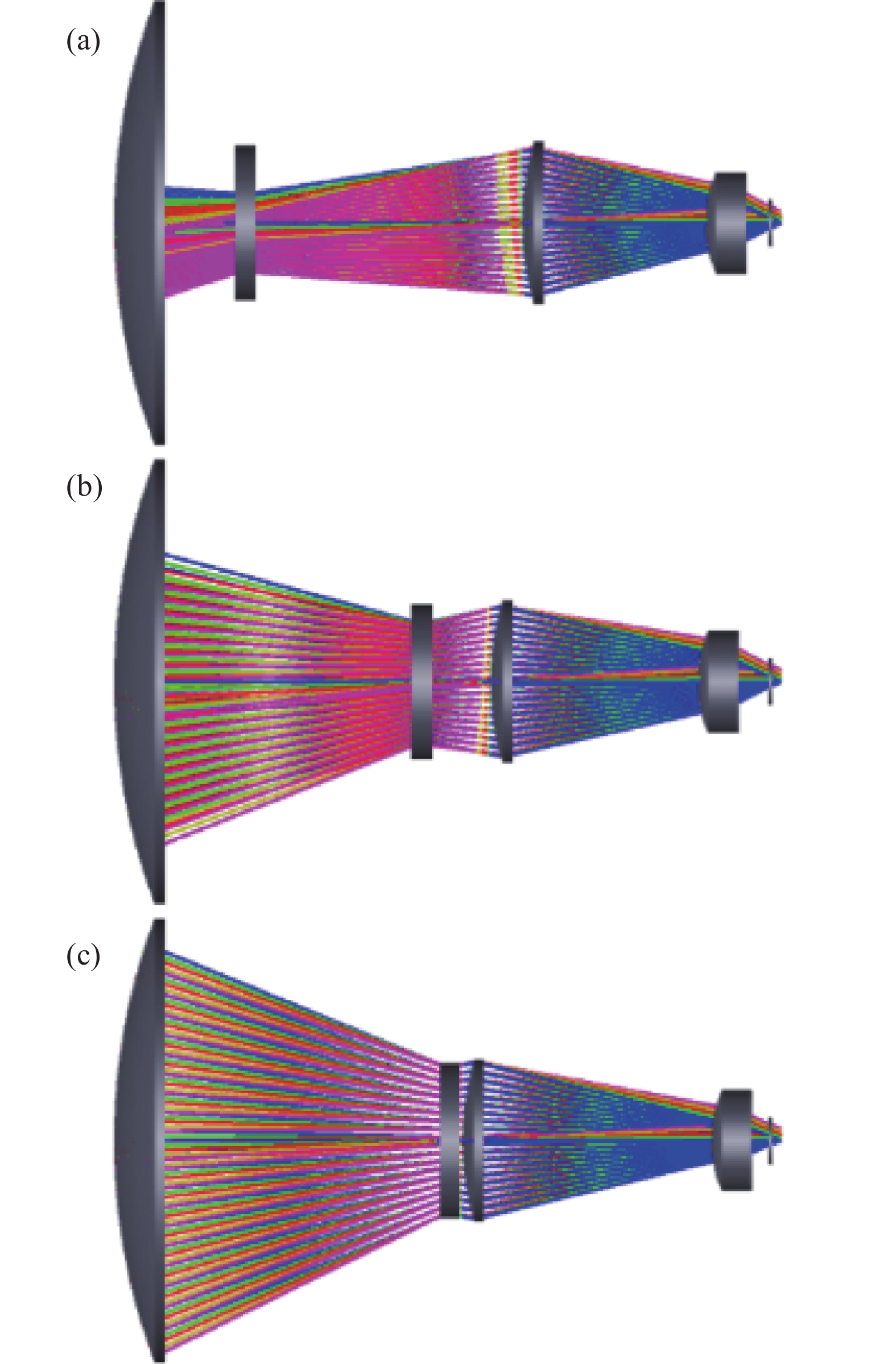
最后,将程序计算的各焦距段参数输入光学辅助设计软件系统,设置多重结构,根据各组元光焦度合理选择透镜形状、透镜材料并设置优化评价函数,设置二元衍射面和高次非球面,以提供更多的优化变量及设计自由度,提升光学系统成像质量。系统在三个焦距位置(短焦距20.7 mm、 中焦距80 mm、长焦距126 mm)的初始架构如图3所示。
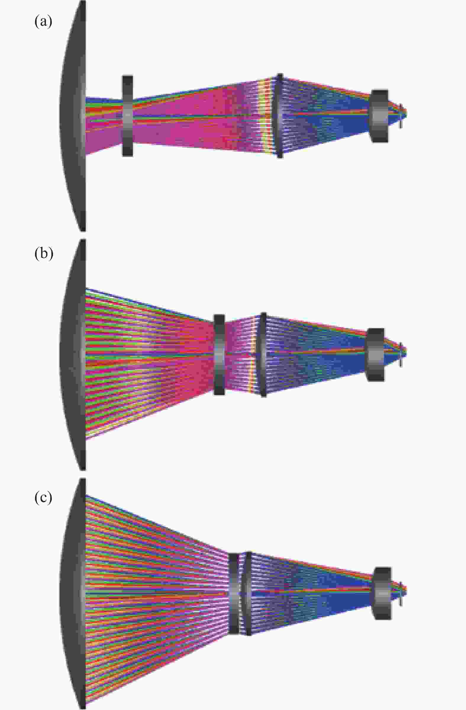
图 3 连续变焦光学多重系统图
Figure 3. Configuration of continuous zoom optical multiple system
-
紧凑低成本非制冷长波红外连续变焦光学系统最终设计结果如图4所示。整个系统共采用四片透镜,最大透镜加工直径为116 mm,光学系统总长为180 mm,光学零件总质量为418 g,远摄比为1.44。前固定组是正光焦度的锗透镜;变倍组为负光焦度的锗透镜;补偿组为正光焦度的锗透镜;第二补偿组为正光焦度低温度折射系数的硫系玻璃透镜。系统共采用一个二元衍射面和三个非球面,将第二补偿组作为调整环节,用于系统主动消热及视距调焦。孔径光阑设置于补偿组前表面,在大视场到小视场连续变焦过程中,系统F#线性变化范围为1.05~1.2,焦距变化范围为20.7~126 mm,对应视场变化范围为21°×16.8°~3.5°×2.8°,变焦过程连续、像质良好,符合设计指标要求。
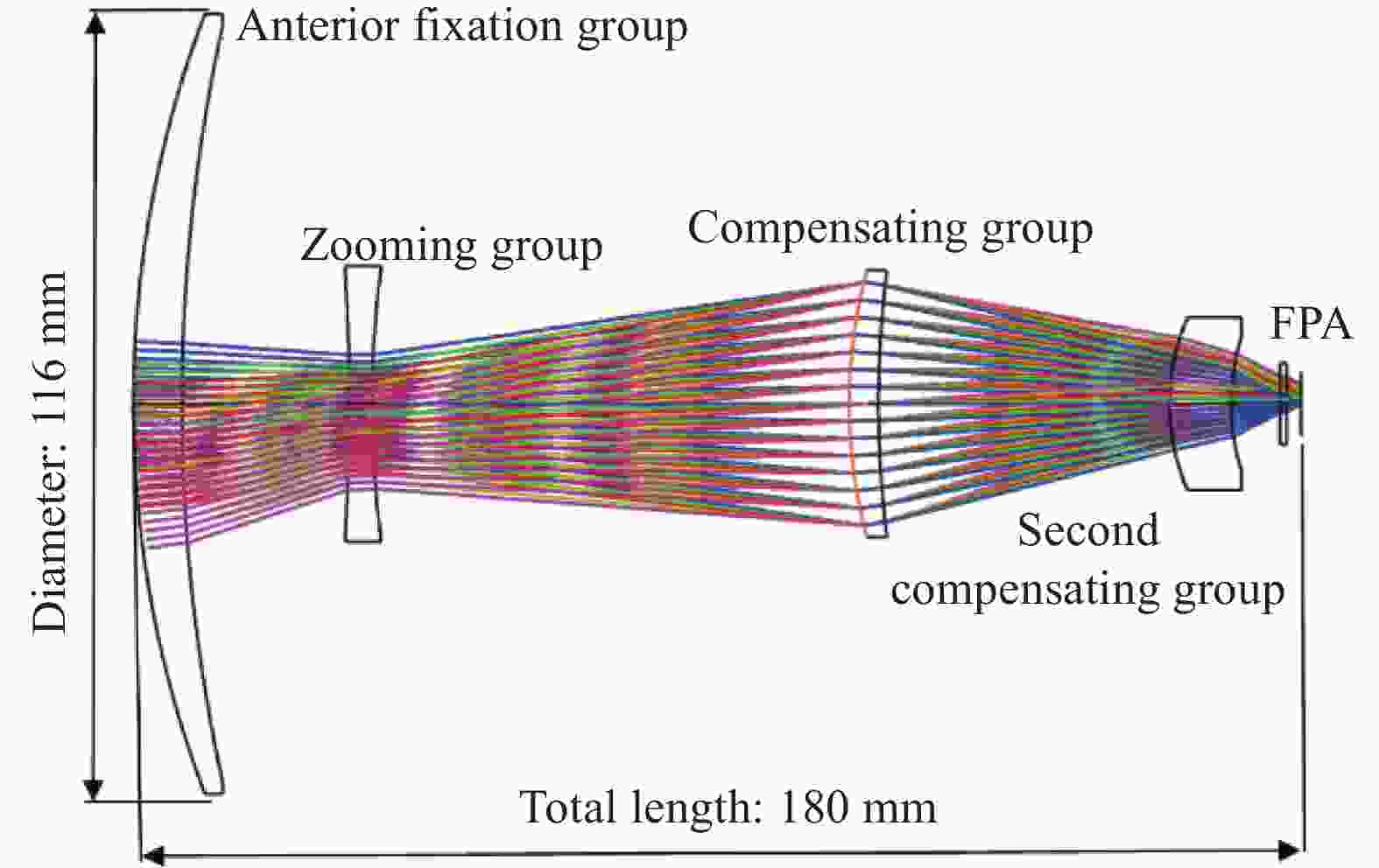
图 4 连续变焦光学系统布局图
Figure 4. Layout of continuous zoom optical system
-
理想光学系统对应的MTF即为系统传函衍射极限。光学系统MTF如图5所示。系统在三个焦距状态的MTF接近衍射极限,成像质量良好。

图 5 连续变焦光学系统MTF曲线
Figure 5. MTF curves of continuous zoom optical system
-
光学系统以主光线的交点为参考点,计算与该点最远的点对应的距离为弥散斑(SPT)几何半径,同时用最小二乘算法计算各点和参考点的平均距离,称为弥散斑均方根(RMS)半径。光学系统点列图如图6所示,系统在三个视场下的最大弥散斑RMS半径值为6.8 μm,表明系统成像清晰,满足使用要求。
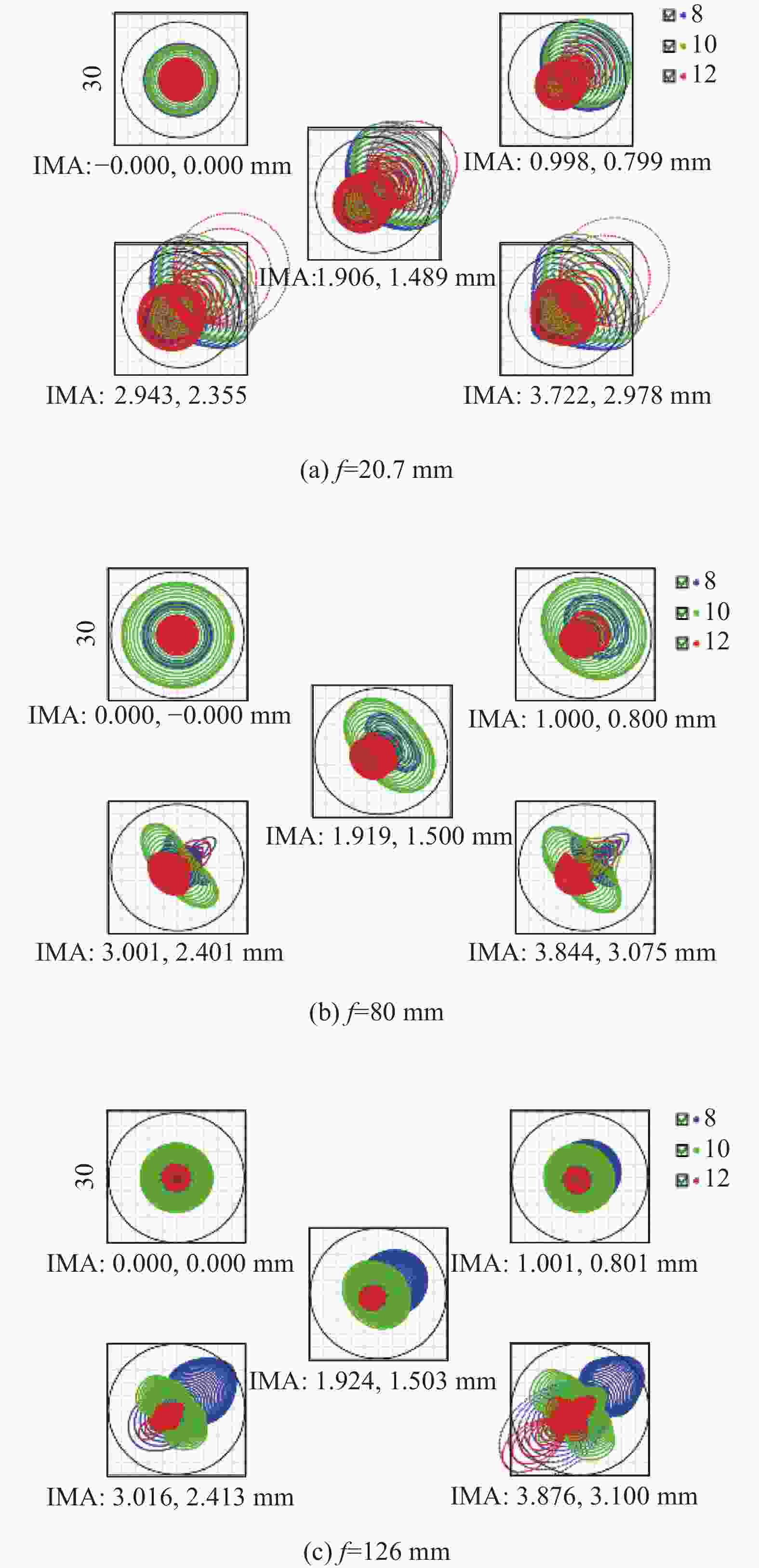
图 6 连续变焦光学系统点列图
Figure 6. Spot diagrams of continuous zoom optical system
-
畸变为理想像高与实际主光线高度的差。光学系统畸变情况如图7所示,在小视场时,最大畸变为0.92%,在大视场时,最大畸变为3.08%,该系统在连续变焦过程中畸变对成像无明显影响。
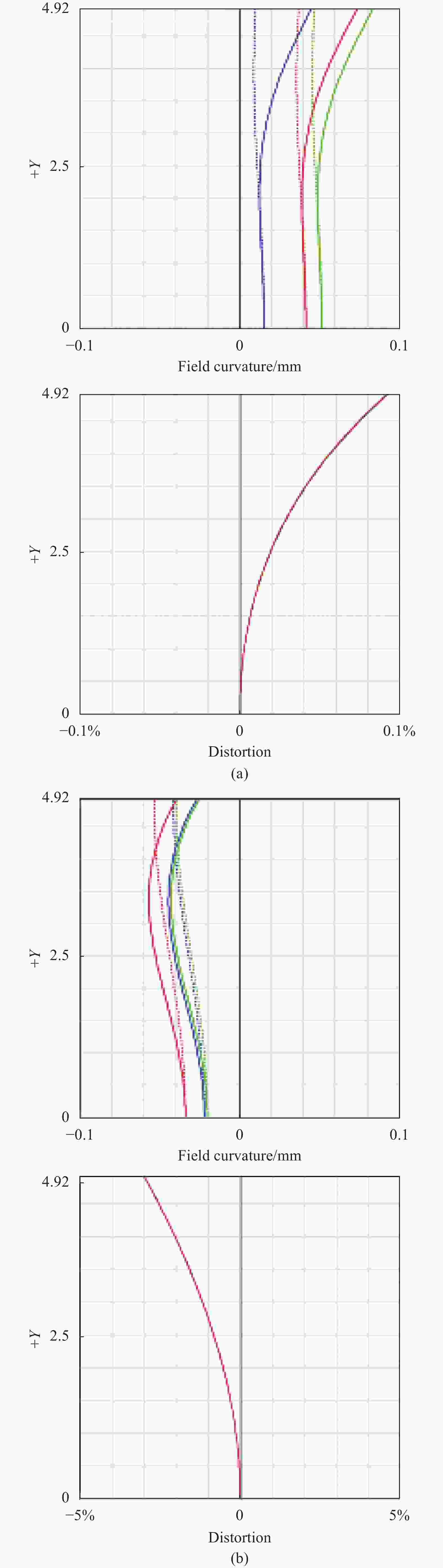
图 7 连续变焦光学系统小视场 (a)及大视场 (b)畸变情况
Figure 7. Distortion diagrams of small field (a) and large field (b) of continuous zoom optical system
-
非制冷长波红外连续变焦光学系统因相对孔径大、常用透镜材料温度折射率系数大等因素,影响光学系统在高低温环境中的成像质量。该系统采用主动补偿技术,即通过移动第二补偿组使光学系统在−40~+60 ℃温度范围成像质量满足使用要求。
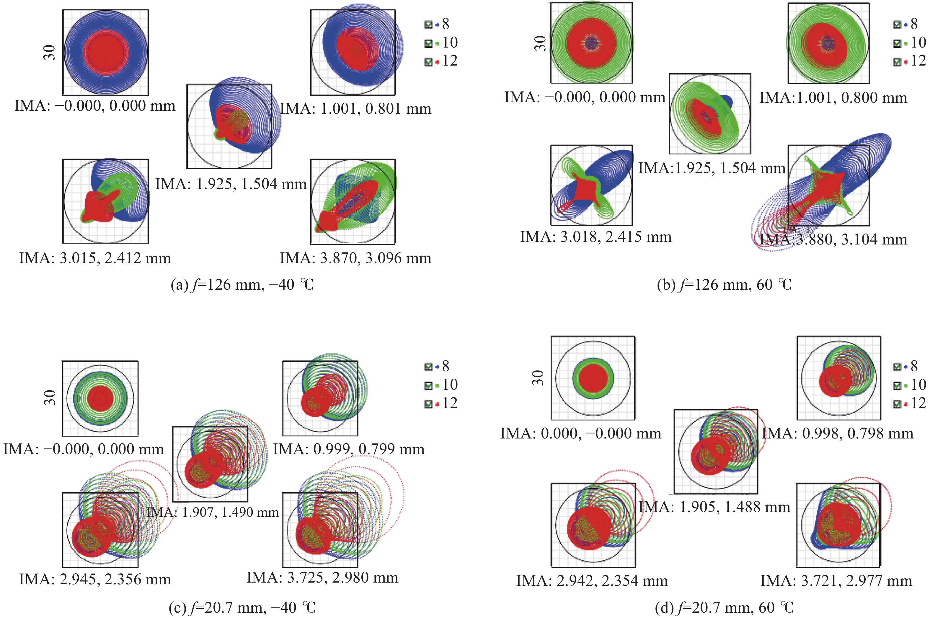
图8为系统在长焦126 mm及短焦20.7 mm时在高低温下经补偿后的光学调制传递函数。图9为系统在长焦126 mm及短焦20.7 mm时在高低温下经补偿后的系统点列图。从高低温传函图及点列图中可以看出,连续变焦系统通过主动补偿在−40~+60 ℃范围内成像质量满足使用要求。

图 8 高低温环境连续变焦光学系统MTF曲线
Figure 8. MTF curves of continuous zoom optical system at high and low temperatures

图 9 高低温环境连续变焦光学系统点列图
Figure 9. Spot diagrams of continuous zoom optical system at high and low temperatures
-
公差分析能够充分评价各项公差对光学系统成像质量的影响,并评估光学零件加工工艺、光机装调的难易程度。对系统成像质量影响较大的制造公差、组装公差要适当调整,并需要多次迭代优化。
光学设计软件运用统计算法对公差进行预估。对于中、高精度光学系统,按照表3修改默认公差表,在系统小视场常温状态采用灵敏度分析得到统计的误差评估表,其中公差最严重项目如图10所示。
表 3 常用Zemax公差表
Table 3. Common tolerance of Zemax
Tolerances Operator Item Target Material TIND Index 0.001 TABB Abbe 1% Surfacequality TFRN Fringes 2 TIRR Irregularity 0.5 Thickness TTHI Thickness/mm 0.03 Surfacetolerances TSDX(Y) Decenter/mm 0.01 TSTX(Y) Tilt/(°) 0.03 Element TEDX(Y) Decenter/mm 0.03 TETX(Y) Tilt/(°) 0.03 
图 10 最严重项目
Figure 10. Worst offenders
从图10可以看出,第一透镜、第二透镜的倾斜与第二透镜前表面的光圈局部公差为“最严重项目”,但对系统成像质量影响较小,容差可控。
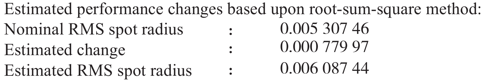
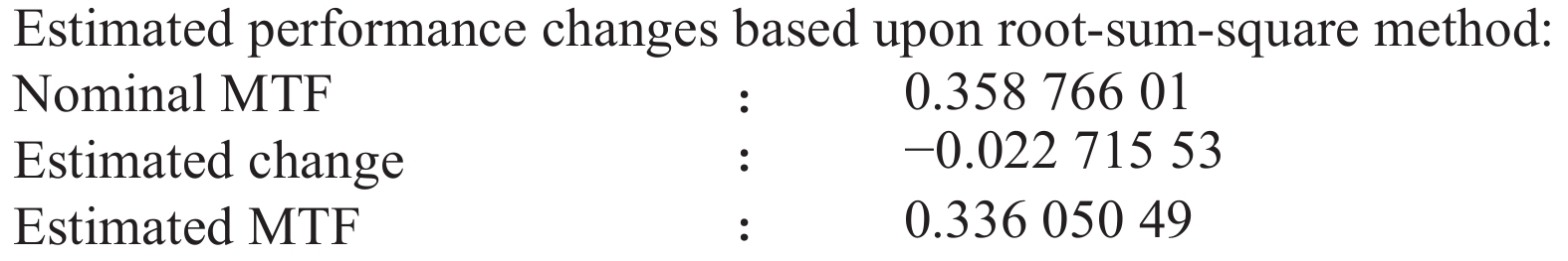
图11、图12分别为系统弥散斑RMS及MTF公差分析结果。从图11可知,系统弥散斑RMS半径的设计值为5.3 μm、改变量统计平均值为0.78 μm以及加工装配后弥散斑RMS半径的估计值为6.09 μm,较好地满足实际使用。从图12可知,系统40 lp/mm处的MTF设计值为0.358,改变量为0.0227,加工装配后MTF的估计值为0.336,满足实际使用需求。

图 11 弥散斑RMS半径估计值
Figure 11. Estimated radius of spot RMS

图 12 MTF估计值
Figure 12. Estimated value of MTF
-
系统在补偿组前表面引入一个二元衍射面用于平衡倍率色差,在锗基底上引入的二元衍射面参数为Norm Radius=22 mm,H1=−10.53,H2=−1.48。计算得到二元衍射面的环带数为1,环带深度为3.18 μm。二元衍射面的位相及周期同元件直径的关系如图13所示,锗基底二元衍射面可采用单点金刚石车削加工。该二元衍射元件衍射环带少,基底材料硬度低,加工简单,成本与非球面透镜相差不大。
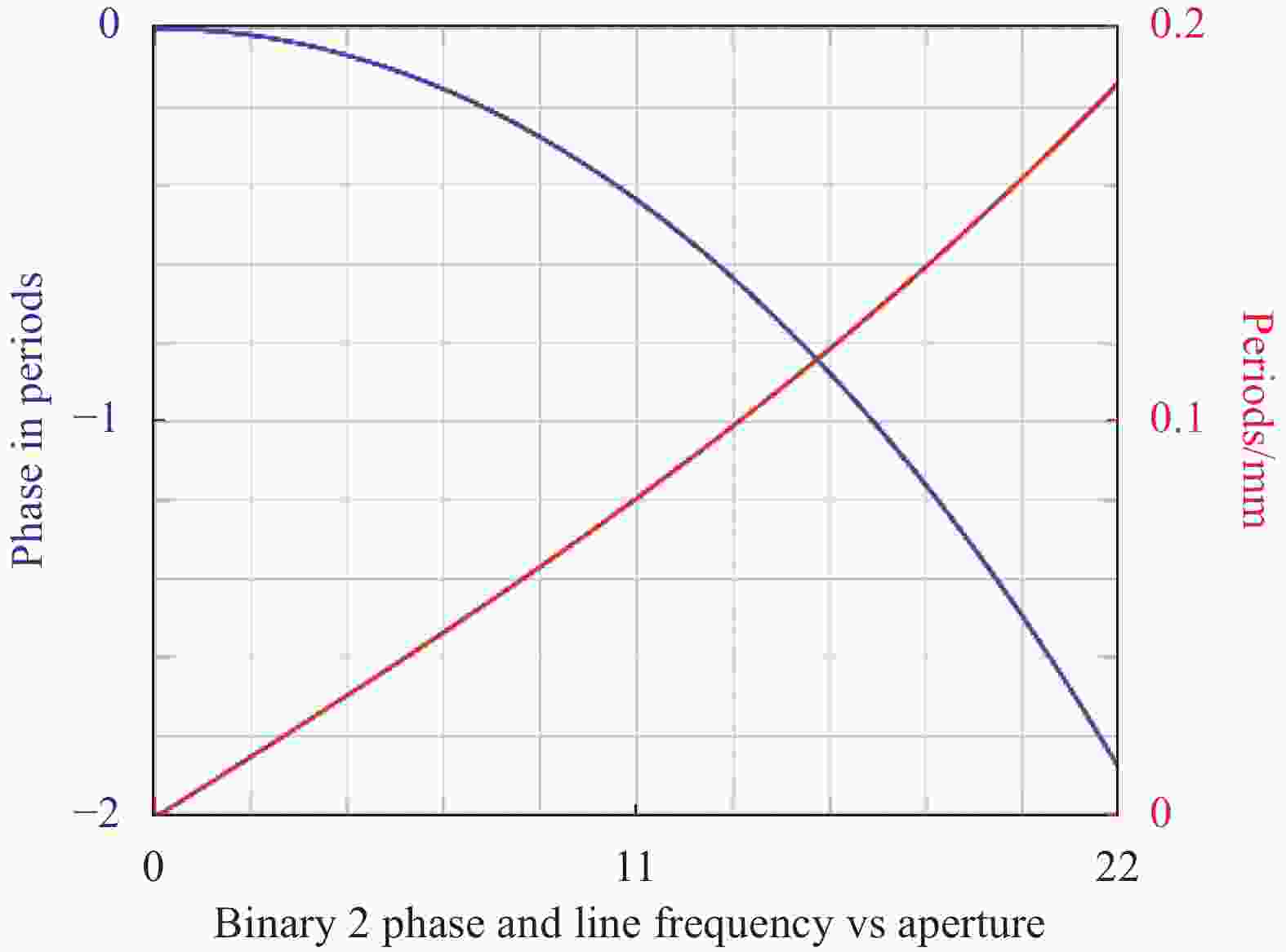
图 13 二元面位相、周期与元件直径的关系
Figure 13. Relationship of phase and periods with diameter of the binary optical element
在8.0~12.0 μm工作波段范围内,取中心波长9.6 μm,利用衍射效率计算公式得到波段平均衍射效率为95.5% ,元件衍射效率如图14所示。考虑光学零件加工引起的遮挡效应及表面粗糙度造成光束散射等因素[8],使用波段平均衍射效率约为92.0%。因此,光学系统透过率为:
$$ \tau =0.96\times 0.975\times 0.92\times 0.975=0.84 $$ 满足系统光学透过率要求。

图 14 二元衍射面衍射效率
Figure 14. Diffraction efficiency of binary optical element
-
系统设计的最后阶段还需要计算变倍组、补偿组及第二补偿组随焦距变化的位移量。优化设计过程中只给出变焦系统五重结构,包含了系统变焦区间(长焦、短焦)及中间三个焦距位置,实际凸轮结构设计需要覆盖整个变焦区间,需要完整的变焦曲线,即以变焦间隔为自变量,以系统焦距为函数的曲线方程,或充分稠密的数据表,该项操作称为变焦曲线的“重整化”[9]。
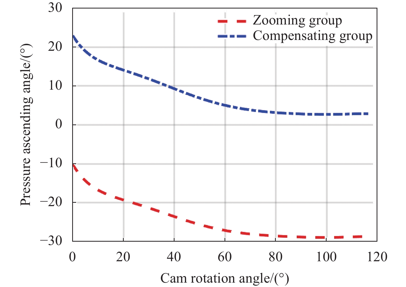
与两个运动组元的正组补偿或负组补偿系统中变倍组与补偿组位置关系一一对应不同,三组联动变焦系统的每一个变倍组位置存在多个补偿解,因此三组联动变焦系统曲线重整需考虑凸轮曲线平滑及单调性。将系统的曲率半径及非球面参数设置为定值,将变焦间隔设为变量,从短焦到长焦插入多重结构按一定的间隔赋值,一般变倍比小于10时,200个焦距位置数据对凸轮结构设计已足够,编制ZPL宏程序自动设置操作数,改变焦距值逐次优化并控制相邻焦距变倍组及补偿组的相对移动量,得到整个变焦区间的变焦间隔及评价函数收敛情况。系统凸轮曲线如图15所示。从图中可知变倍组最大行程为56 mm,补偿组最大行程为17.5 mm,第二补偿组最大行程为4.5 mm;变倍组、补偿组曲线平滑无拐点采用凸轮轨道驱动,凸轮转角与变倍组与补偿组的压力升角关系如图16所示。第二补偿组采用单个电机驱动,有利于系统视距调焦及主动消热,考虑高低温消热补偿行程,该组最大移动量为6.6 mm。
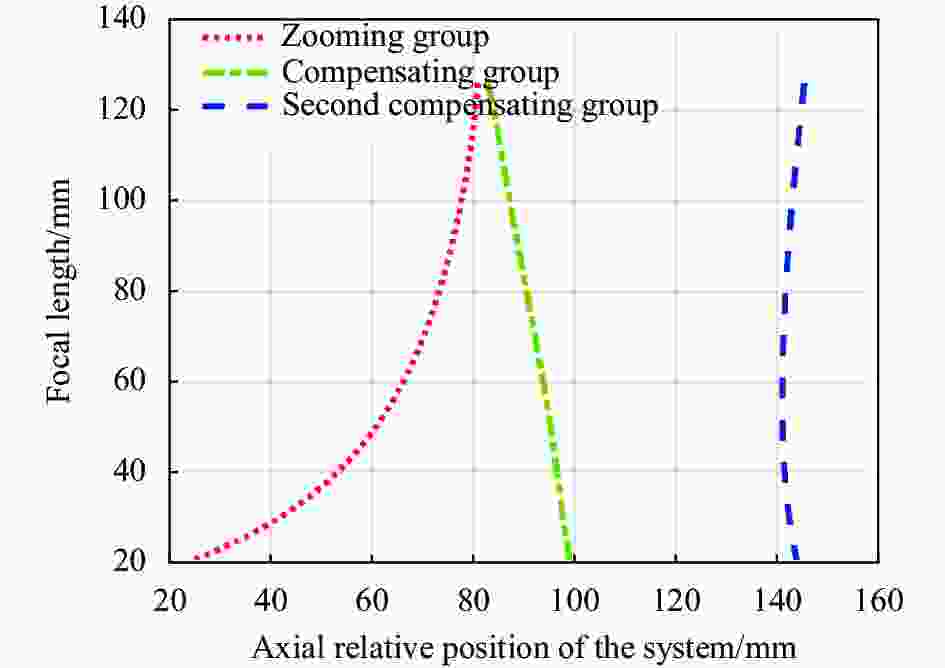
图 15 连续变焦光学系统凸轮曲线
Figure 15. Cam curve of continuous zoom optical system
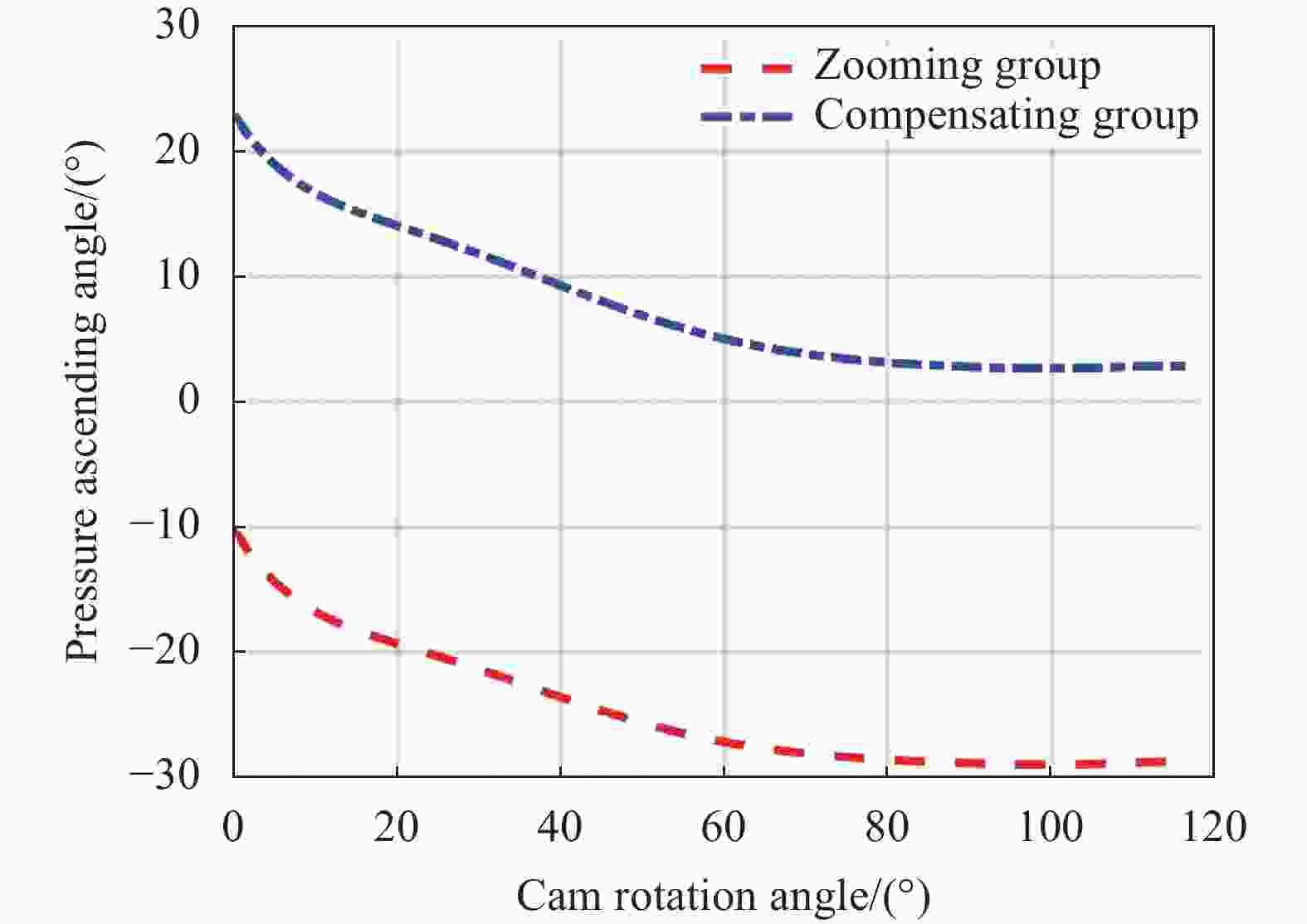
图 16 凸轮转角与压力升角关系
Figure 16. Relationship between cam rotation angle and pressure ascending angle
-
随着红外热像仪朝着SWaP-C方向快速迭代,影响非制冷连续变焦红外热像仪尺寸、体积、质量、价格等方面的变焦光学系统日益朝着总长短、体积小、成本低、性能高、环境适应性好等方面发展,以满足民用、军事等各方面的应用需求。基于640×512像元间距12 μm的非制冷焦平面探测器,采用变F#设计方法、引入三组联动变焦设计技术、通过主动补偿消热差,实现了一款四片透镜结构的紧凑低成本连续变焦光学系统设计。系统焦距变化范围为20.7~126 mm,相应F#在1.05~1.2之间变化,对应视场变化范围为21°×16.8°~3.5°×2.8°,变倍比为6.0×,最大物镜口径116 mm,光学总长180 mm,远摄比为1.44,光学零件总质量418 g,零件加工工艺成熟,加工装调容差较好,变焦凸轮曲线平滑,凸轮轨道易于加工,运动组元伺服控制简单,系统在−40~+60 ℃环境下成像清晰,满足高低温使用要求。该紧凑低成本非制冷长波红外连续变焦光学系统将在导航、侦察、警戒、搜索及跟踪等无人系统平台或手持热像仪产品中具有广阔的市场前景,推动非制冷红外热像仪进一步朝着降低SWaP-C方向发展。
Compact and low-cost uncooled LWIR continuous zoom optical design
-
摘要: 随着红外技术的快速发展,SWaP-C (尺寸小、质量轻、功耗低、成本低)概念已深入红外热像仪整机设计全过程。在非制冷连续变焦红外热像仪设计中,相对已模块化的非制冷探测器与成像电路、光学系统影响整机包络尺寸、产品质量及价格成本,因此设计一款总长短、质量轻、成本低、性能高的非制冷长波红外连续变焦光学系统将具有广阔的市场前景。非制冷长波红外连续变焦光学因相对孔径大、光学材料种类少等因素存在系统小型化和无热化设计难题,通过采用变F#设计方法约束物镜尺寸;利用三组联动变焦技术平衡像差、压缩系统总长;通过主动补偿的消热差技术使得系统在−40~+60 ℃温度范围成像质量良好,实现四片透镜构成的非制冷长波红外连续变焦光学系统设计。该系统工作波段为8~12 μm,焦距变化范围为20.7~126 mm,对应F#为1.05~1.2,视场变化范围为21°×16.8°~3.5°×2.8°,变倍比为6.0×,最大物镜直径116 mm,光学系统总长180 mm,光学零件总质量418 g。该光学系统具有轻小型、高性能、低成本等SWaP-C特征,将在无人装备平台及手持热像仪设备中得到广泛应用。Abstract:
Objective With the rapid development of infrared technology, the concept of SWaP-C (small size, light weight, low power consumption and low cost) has been expanded from infrared detector to the whole design process of infrared thermal imager. In the design of uncooled continuous zoom infrared thermal imager, compared with the modularized uncooled detector and imaging circuit, the optical system affects its envelope size, product weight and price cost. A light, small, low-cost, high-performance uncooled infrared optical system needs to achieve the following five goals. First, the number of lenses is as small as possible. Second, the length of the optical system is short. Third, the diameter of the large objective lens is small. Fourth, the optical system has high MTF. Fifth, the optical system has good environment adaptability. Therefore, the design of an uncooled LWIR continuous zoom optical system with short length, light weight, low cost and high performance will have broad market prospects. Methods There are difficulties in miniaturization and athermalization design of uncooled LWIR continuous zoom optical system due to its large relative aperture and few kinds of infrared optical materials. The purpose of compressing the total length of system and balancing aberration is achieved by using three groups of linkage zoom technology. Through the active compensation of athermalization technology, the system has good imaging quality in the temperature range of −40-60 ℃. The specific design process of the optical system is as follows. Firstly, the calculation program is compiled according to the three groups of linkage continuous zoom models. According to the design index, the initial optical form is calculated by considering the total optical length, lens focal length distribution and lens spacing. The parameters are input into Zemax optical design software to establish the ideal optical model. Secondly, the shape and material are reasonably selected according to the focal length of the lens, and the evaluation function is set to enter the optimization and global optimization. Thirdly, according to the results of the evaluation function, the imaging quality at normal temperature and at high and low temperature is evaluated. Then, the tolerance analysis of optical system is carried out to make the system meet the tolerance range of processing and assembly requirements. Finally, the optical system zoom curve renormalization operation is carried out to complete the optical system design. The design flow chart is shown (Fig.2). Results and Discussions The final design result of the compact and low-cost uncooled LWIR continuous zoom optical system is shown (Fig.4). The whole system uses four lenses with the working band of 8-12 μm, the focal length range of 20.7-126 mm, the corresponding F# of 1.05-1.2, the field of view range of 21°×16.8°-3.5°×2.8°. The zoom ratio is 6.0×, the maximum machining diameter is 116 mm, the total length of the optical system is 180 mm, the total weight of the optical part is 418 g, and the telephoto ratio is 1.44. The MTF, SPT and distortion of the optical system are analyzed by Zemax optical simulation software. The system imaging is clear and meets the requirements. The MTF of the optical system at normal temperature (Fig.5), the SPT of the optical system (Fig.6). and the system distortion (Fig.7) are shown. The imaging quality of the optical system is evaluated at high and low temperature, and the optical system meets the requirements of athermalization. The tolerance of the optical system is estimated by statistical algorithm, and the tolerance of the system meets the actual use requirements. By renormalizing the cam curve of the optical system, the motion curves of the three lenses are obtained (Fig.15). The optical system achieves the SWaP-C goals. Conclusions Based on a 640×512 uncooled focal plane detector with pixels size of 12 μm, a compact low-cost continuous zoom optical system composed of four lenses was designed using variable F# design method, three groups of linkage zoom design technology and active compensation for athermalization. The focal length of the system varies from 20.7 mm to 126 mm, the total optical length is 180 mm, the lens processing technology is mature, the processing and adjustment tolerance is good, the zoom cam curve is smooth, the cam track is easy to process, and the motion servo control is simple. The system has clear imaging in the environment of −40 ℃ to +60 ℃. The optical system has the characteristics of light weight, high performance and low cost. It will be widely used in unmanned equipment platform and handheld thermal imager equipment, and promote the development of uncooled infrared thermal imager in the direction of reducing SWaP-C. -
图 1 三组联动连续变焦系统原理图
Figure 1. Principle diagram of continuous zoom optical system with three group linkage
图 7 连续变焦光学系统小视场 (a)及大视场 (b)畸变情况
Figure 7. Distortion diagrams of small field (a) and large field (b) of continuous zoom optical system
图 8 高低温环境连续变焦光学系统MTF曲线
Figure 8. MTF curves of continuous zoom optical system at high and low temperatures
图 9 高低温环境连续变焦光学系统点列图
Figure 9. Spot diagrams of continuous zoom optical system at high and low temperatures
图 13 二元面位相、周期与元件直径的关系
Figure 13. Relationship of phase and periods with diameter of the binary optical element
图 16 凸轮转角与压力升角关系
Figure 16. Relationship between cam rotation angle and pressure ascending angle
表 1 光学系统技术指标
Table 1. Technical parameters of optical system
Parameter Value Spectral range/μm
Zoom ratio
Field of view/(°)
F#
Focal length/mm
Transmittance
Working temperature/℃8-12
6.0∶1
21×16.8-3.5×2.8
≤1.2
20.7-126
>80%
−40-60 下载: 导出CSV
表 2 光学系统间隔初始参数
Table 2. Initial parameters of optical system spacing
Focal length/mm 126 104 80 40 20 f1/f2 spacing/mm 71.2 67.9 61.6 40.7 16.4 f2/f3 spacing/mm 6.3 11.1 19.3 46.4 78.4 f3/f4 spacing/mm 59.9 56.0 52.3 46.5 39.6 Back intercept/mm 5.7 8.1 9.9 9.5 8.7
下载: 导出CSV
表 3 常用Zemax公差表
Table 3. Common tolerance of Zemax
Tolerances Operator Item Target Material TIND Index 0.001 TABB Abbe 1% Surfacequality TFRN Fringes 2 TIRR Irregularity 0.5 Thickness TTHI Thickness/mm 0.03 Surfacetolerances TSDX(Y) Decenter/mm 0.01 TSTX(Y) Tilt/(°) 0.03 Element TEDX(Y) Decenter/mm 0.03 TETX(Y) Tilt/(°) 0.03
下载: 导出CSV
-
[1] Asida N. Reduced SWaP-C lenses for UAV and drone thermal imaging [C]//SPIE, 2021, 11737: 117370G. [2] Yu Lijing, Tang Libin, Yang Wenyun, et al. Research progress of uncooled infrared detectors [J]. Infrared and Laser Engineering, 2021, 50(1): 20211013. (in Chinese) [3] Zhang Faqiang, Fan Xiang, Zhu Bin, et al. Athermal design of long-wave infrared optical system with hybrid refractive/diffractive [J]. Infrared and Laser Engineering, 2015, 44(4): 1158-1163. (in Chinese) doi: 10.3969/j.issn.1007-2276.2015.04.010 [4] Cao Chao, Liao Zhiyuan, Bai Yu, et al. Design of large zoom ratio long-wave infrared zoom system with compound zoom method [J]. Opt Eng, 2018, 57(2): 025104. [5] Bao Jiaqi, Ji Zijuan, Ge Zhenjie, et al. Design of a long wave infrared continuous zoom optical system with high resolution [J]. Opto-Electronic Engineering, 2014, 41(2): 75-81. (in Chinese) [6] Wu Haiqing, Wang Peng. Design of miniaturized large-format uncooled infrared continuous zoom optical system [J]. Infrared, 2020, 41(2): 1-6. (in Chinese) doi: 10.3969/j.issn.1672-8785.2020.02.001 [7] 陶纯堪. 变焦距光学系统设计[M]. 北京. 电子国防工业出版社. 1988. Tao Chunkan. Zoom Focus Optics System Design[M]. Beijing: National Defense Industry Press, 1988. (in Chinese) [8] Zhang Faping, Zhang Huawei. Design of long-wave athermal optical system based on binary diffractions surface [J]. Infrared Technology, 2020, 42(1): 25-29. (in Chinese) [9] Song Feijun, Chen Xiao, Liu Chang. Introduction to Modern Optical System Design[M]. Beijing: Science Press, 2019: 499. (in Chinese) -

 点击查看大图

计量
- 文章访问数: 183
- HTML全文浏览量: 34
- PDF下载量: 84
- 被引次数: 0


