


 下载:
下载:


-
光子集成芯片(Photonics Integrated Circuits, PICs)以光子作为信息传输和处理的载体,具有低损耗、大带宽、低功耗、抗电磁干扰等优势,有望突破集成电路电子瓶颈的限制,在光通信、光学传感、雷达、光子计算、医疗检测等领域均有广泛的应用[1-4]。基于微纳加工技术,PIC实现了激光器、调制器、探测器、分束器等多种功能器件的片上集成,器件间通过光波导互联,进而构建功能丰富的光学系统。
集成光学器件的温度稳定性是影响PICs性能的重要因素,是PICs工程化应用中面临的主要问题之一 [5-13]。由于光波导材料固有的热光特性,当温度发生波动时,波导芯层、包层材料的折射率会随之改变,进而影响光波导的模式和传输的光程及相位,最终导致光学器件的性能变化。因此,要对光学器件性能随温度的漂移进行抑制和补偿,以提高PICs的温度稳定性。
目前,补偿温度漂移的方案主要有两种:一是采用外部温控装置将芯片的温度控制在一定范围内,降低环境温度波动带来的影响[12]。优点是温控电路技术成熟,且不需改变原有光学器件的结构,普适性强;但温控精度有限,不能实现对光学器件性能随温度漂移的主动补偿,且会增加系统体积,难以与光学器件进行集成。二是优化光波导或器件结构,减弱甚至抑制温度对传输特性的影响,从本质上补偿温度噪声。采用具有负热光系数的材料如聚合物[8]、氧化钛[9]等优化波导结构,使得波导的传输特性不随温度漂移,波导结构的变化导致传输损耗增加。利用具有非对称臂的MZI补偿谐振特性漂移[10-11],增加了系统体积。利用电极对波导进行局部加热,调谐相位,实现对相位漂移的主动补偿[5,13],调谐速率慢,功耗大。因此,需要开发一种紧凑、高效且普适性强的温度不敏感结构,以适用于多种集成光学器件。
长程表面等离激元(Long Range Surface Plasmon Polariton, LRSPP)波导[14-15]以金、银等贵金属作为芯层材料,具有光电复用的特性,可通过芯层直调实现相位调谐;包层为具有负热光特性的聚合物材料,其独特的优势适合用于对集成光学器件进行温度补偿。然而,LRSPP波导传输损耗大,太长的LRSPP波导会引入较大的损耗,难以直接实现大规模PICs。基于此,文中将超低损耗的氮化硅(Si3N4)波导与LRSPP波导相结合,充分发挥Si3N4波导低损耗和LRSPP波导光电复用的特性,提出了基于Si3N4与LRSPP的温度不敏感波导结构。分析了混合波导结构的温度特性,当Si3N4和LRSPP波导满足最佳长度比条件时,可实现温度不敏感;当不满足最佳长度比时,利用LRSPP波导的光电复用特性实现对温度漂移的主动补偿。由于LRSPP波导仅支持TM模式传输,偏振消光比高,使得混合波导结构具有良好的单偏振特性。此外,该混合结构无需特殊的材料选择和复杂的结构设计,在不改变原有的Si3N4波导和LRSPP波导结构的情况下实现温度不敏感,适用于改善基于Si3N4平台的集成光子器件和芯片温度漂移的问题。
-
光波导是PICs的核心和基础单元结构,其损耗决定了芯片的性能。得益于微纳加工技术的发展,CMOS工艺兼容的绝缘体上硅(Silicon on Insulator, SOI)[16-17]、氧化硅(SiO2)[16,18]和Si3N4 [19]波导的传输损耗均得以极大的降低,是研制PICs的主要材料。随着光子集成向大规模和超高密度集成方向发展,具有高折射率差的SOI和Si3N4更具竞争力。针对上述三种材料,考虑利用LRSPP波导进行温度补偿的可行性。由于LRSPP波导仅支持TM模式,只有TM偏振态的光才能激励起SOI波导、SiO2波导、Si3N4波导和LRSPP波导间的传输模式,因此只需要考虑TM模式下的耦合情况。利用有限元算法仿真得到了SOI波导、SiO2波导、Si3N4波导和LRSPP波导的TM模,如图1所示。LRSPP波导和Si3N4波导具有相似的模式分布和相近的模式面积,与SOI波导和SiO2波导模式差异显著,表明LRSPP波导和Si3N4波导可能会实现高效的模式耦合,即LRSPP波导更适合用于对Si3N4波导进行调谐。
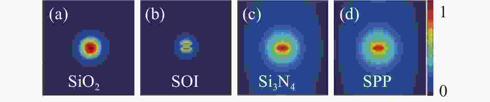
图 1 (a) SiO2波导的TM模;(b) SOI波导的TM模;(c) Si3N4波导的TM模;(d) LRSPP波导的TM模
Figure 1. TM mode of (a) SiO2 waveguide; (b) SOI waveguide; (c) Si3N4 waveguide; (d) LRSPP waveguide
由此,为了实现对Si3N4波导相位的调谐,提出了基于Si3N4波导和LRSPP波导的相位调谐单元。如图2(a)所示,SPP波导直接嵌入Si3N4波导中。其中,Si3N4波导的芯层和包层材料分别为Si3N4和SiO2;LRSPP波导的芯层材料为金,包层为聚合物材料ZPU;金属电极与LRSPP波导的金属芯层相连,用于芯层调制。Si3N4波导芯层宽度为w1,芯层厚度为h1;LRSPP波导芯层宽度为w2,芯层厚度为h2。

图 2 (a) 基于Si3N4和LRSPP波导的温度不敏感结构示意图;(b) Si3N4波导横截面;(c) LRSPP波导横截面
Figure 2. (a) Schematic diagram of temperature insensitive structure based on Si3N4 waveguide and LRSPP waveguide; (b) Cross-section of the Si3N4 waveguide; (c) Cross-section of the LRSPP waveguide
针对Si3N4波导和LRSPP波导间的对接耦合可行性,利用模式重叠积分分析了两种波导在不同波导尺寸下的模式耦合效率。当Si3N4波导和LRSPP波导宽度不一致时,波导间的耦合效率急剧降低,因此,后续的研究均在Si3N4波导和SPP波导宽度相等(w1 = w2)的条件下进行。当Si3N4波导宽度w1和LRSPP波导宽度w2均为4 μm时,耦合效率和波导芯层厚度的关系如图3(a)所示。当LRSPP波导芯层厚度一定,随着Si3N4波导芯层厚度的增加,耦合效率先上升后降低;且不同LRSPP波导厚度下均存在一个最佳的Si3N4波导厚度使得耦合效率最高,最佳耦合效率均大于99.9%(耦合损耗几乎可以忽略)。随着LRSPP波导厚度的增加,实现最佳耦合效率的Si3N4波导的厚度也随之增加(图3(b)的插图)。此外,Si3N4波导和LRSPP波导的耦合效率也受波导宽度的影响。如图3(b)所示,随着波导宽度的增加,耦合效率先增加后降低;当波导宽度为 4 μm时,耦合效率最高。此外,还对比了Si3N4波导和LRSPP波导的模式面积差|δmode area|,如图3(c)所示,当Si3N4波导芯层厚度h1增加时,|δmode area|先降低后增加,其变化趋势与耦合效率相反;且当|δmode area|最小时(接近0),耦合效率最高,表明Si3N4波导和LRSPP波导间的模式面积越接近,耦合效率越高。
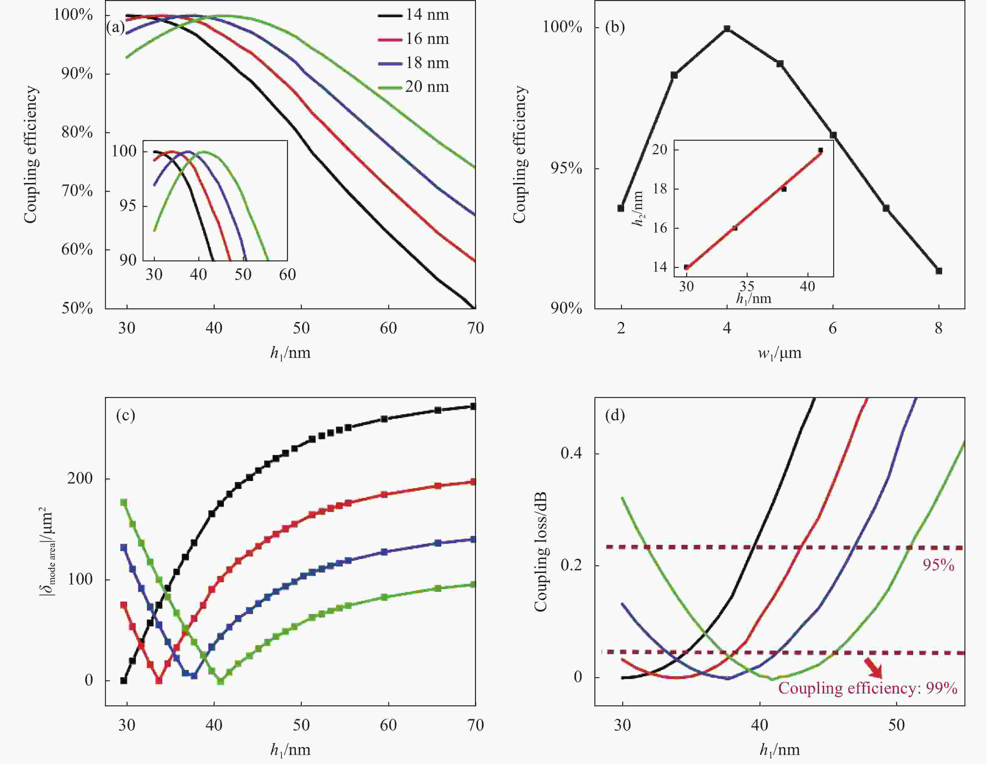
图 3 (a) Si3N4波导和LRSPP波导的耦合效率与波导厚度的关系,插图是耦合效率的局部放大图;(b) Si3N4波导和LRSPP波导的耦合效率与波导宽度的关系,插图是最佳耦合效率下波导的厚度关系图;(c) Si3N4波导和LRSPP波导的模式面积差与波导厚度的关系;(d) Si3N4波导和LRSPP波导的耦合损耗与波导厚度的关系
Figure 3. (a) Coupling efficiencies of the Si3N4 waveguide and LRSPP waveguide with different core heights. Inset: the zoom of the coupling efficiency; (b) Coupling efficiencies of the Si3N4 waveguide and LRSPP waveguide with different core widths. Inset: optimal coupling efficiency with different core heights; (c) Mode area differences of the Si3N4 waveguide and LRSPP waveguide with different core heights; (d) Coupling losses of the Si3N4 waveguide and LRSPP waveguide with different core heights
为了进一步衡量Si3N4波导和LRSPP波导的耦合效果,计算了波导间的耦合损耗,如图3(d)所示。当LRSPP波导厚度h2一定时,随着Si3N4波导芯层厚度h1增加,耦合损耗先降低后上升。当Si3N4波导和LRSPP波导的耦合效率最大时,其耦合损耗低于0.005 dB,几乎可以忽略不计;当耦合效率为99%和95%时,对应的耦合损耗分别为0.0437 dB和0.2228 dB。当SPP波导芯层厚度h2为14 nm、16 nm、18 nm及20 nm时,Si3N4波导的芯层厚度h1分别为30~34 nm、30~38 nm、33~42 nm及37~46 nm时,能实现耦合效率大于99%的高效耦合;Si3N4波导芯层厚度分别为30~40 nm、30~43 nm、30~47 nm及33~51 nm时,能实现耦合效率大于95%的有效耦合。上述结果表明,Si3N4波导和LRSPP波导能在较大的尺寸范围内实现高效耦合。
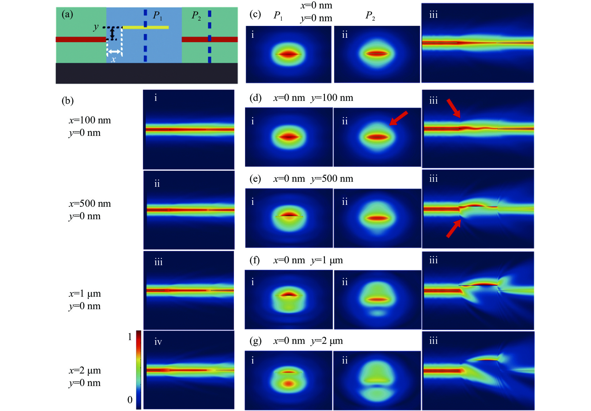
在上述波导耦合的分析中,Si3N4波导和LRSPP波导的芯层处于中心对准的理想状态。然而在实际制备的过程中,由于工艺误差极有可能导致波导芯层中心横向(x方向)或纵向(y方向)错位(如图4(a)所示),进而影响耦合效率。利用时域有限差分法研究了Si3N4波导和LRSPP波导在x方向和y方向上中心位置有偏差时的传输情况(假设一个方向偏离时,另一方向上处于中心对准状态)。如图4(b)所示,在x方向上小于1 μm的偏移对耦合传输影响较小,这是因为仅有横向偏离时,两波导的模式处于中心对准状态,光信号通过短间隙的包层传输,模式发散较弱,仍有较多的能量耦合进另一根波导中;当横向偏移为2 μm时(图4(b)iv),模式在包层中传输时有轻微发散,有部分光向包层耗散,影响了波导的耦合效率,导致输出端的光信号强度显著降低。当y方向上发生偏移时,仿真了光的传输过程,并监测了在LRSPP波导(P1点)和输出Si3N4波导(P2点)的模式。如图4(c)~(g)所示,y = 100 nm时,光在传输过程中无明显发散,且P2点处的模式与无偏移时的模式接近,仍能实现Si3N4波导和LRSPP波导间的高效耦合;当y = 500 nm时,对接处有明显的发散现象,Si3N4的输出光强显著降低,耦合效率显著降低;当偏移达2 μm时,仅有少部分散射到包层的光耦合进LRSPP波导,耦合损耗大。
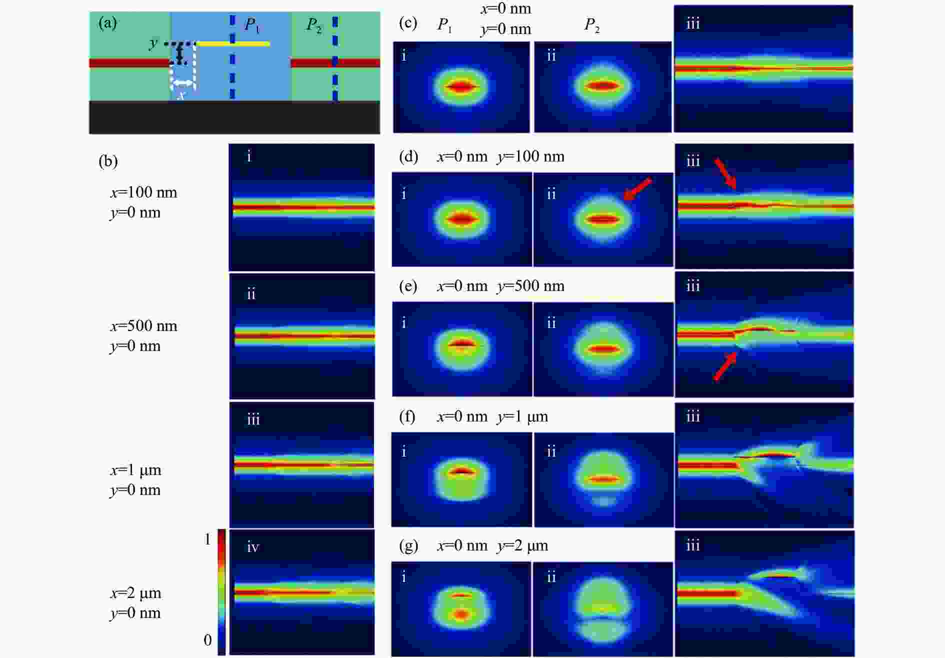
图 4 (a) Si3N4波导和LRSPP波导在横向(x方向)和纵向(y方向)上的偏移;(b) Si3N4波导和LRSPP波导横向偏移时的传输场;(c)~(g) Si3N4波导和LRSPP波导在不同纵向偏移时的特性:(i) P1点的模式分布,(ii) P2的模式分布,(iii)传输场
Figure 4. (a) Offset between the Si3N4 waveguide and LRSPP waveguide in horizontal (x) and vertical (y) direction; (b) Transmission field of the Si3N4 waveguide and LRSPP waveguide with lateral offset; (c)-(g) Properties of the Si3N4 waveguide and LRSPP waveguide with longitudinal offset: (i) mode distribution in P1, (ii) mode distribution in P2, (iii) transmission field
-
针对提出的基于Si3N4波导和LRSPP波导的混合结构,对其温度特性进行分析。混合波导结构传输的相位为:
$$ \varphi =\frac{2\pi }{\lambda }\cdot ({n}_{\rm eff1}\cdot {L}_{1}+{n}_{\rm eff2}\cdot {L}_{2}) $$ (1) 式中:λ为波长;neff1为Si3N4波导的模式有效折射率;L1为Si3N4波导的长度;neff2为LRSPP波导的模式有效折射率的实部;L2为LRSPP波导的长度。
当温度发生变化时,相位随温度的漂移可用下式表征:
$$ \begin{split} \frac{\text{d}\varphi }{\text{d}T}=&\frac{2\pi }{\lambda }\cdot \left[\left(\frac{\text{d}{n}_{\rm eff1}}{\text{d}T}+{n}_{\rm eff1}\cdot {\alpha }_{1}\right)\cdot {L}_{1}\right.+\\&\left.\left(\frac{\text{d}{n}_{\rm eff2}}{\text{d}T}+{n}_{\rm eff2}\cdot {\alpha }_{2}\right)\cdot {L}_{2}\right] \end{split} $$ (2) 式中:T为环境温度;α1为Si3N4波导衬底的热膨胀系数;α2为LRSPP波导衬底的热膨胀系数。
由Drude模型可得金在1550 nm波长下的折射率随温度的变化关系为[9]:
$$ \begin{split} {n}_{\mathrm{A}\mathrm{u}}\left(T\right)=& {n}_{\mathrm{r}}\left(T\right)+{i}{n}_{\mathrm{i}}\left(T\right)\\ {n}_{\mathrm{r}}\left(T\right)=& 0.054\;3+0.001\;68T \\ {n}_{\mathrm{i}}\left(T\right)=& 11.617-3.204\times {10}^{-4}T-2.965\times {10}^{-7}{T}^{2} \end{split} $$ (3) 式中:nAu(T)为金在温度T下的折射率;nr(T)为金的折射率实部;ni(T)为金的折射率虚部。
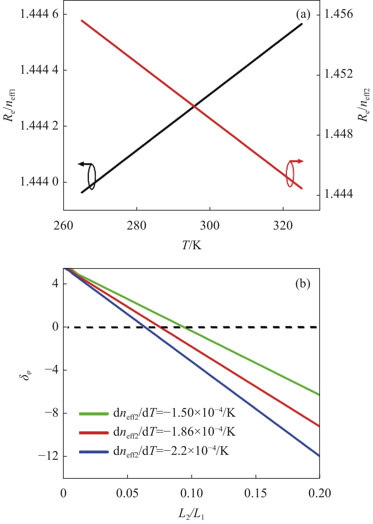
根据材料的热光系数,利用有限元算法计算了Si3N4波导和LRSPP波导在不同温度下的模式有效折射率,如图5(a)所示。Si3N4波导和LRSPP波导的模式有效折射与温度呈线性关系,由此可得公式(2)中dneff1/dT和dneff2/dT分别为1×10−5和−1.86×10−4,与包层材料的热光系数接近,表明波导模式有效折射率的热光特性主要取决于包层材料的热光系数。Si3N4波导的包层为SiO2,热光系数为正;LRSPP波导的包层材料为聚合物,具有负的热光系数。当温度发生变化时,Si3N4波导和LRSPP波导折射率的变化趋势相反。因此,可利用LRSPP波导的负热光特性对Si3N4波导相位的漂移进行补偿。由公式(2)可知,通过设计Si3N4波导和LRSPP波导的长度实现温度不敏感。相位变化与波导长度比的关系如图5(b)所示。当LRSPP波导的热光系数为−1.86×10−4时,L2/L1 = 0.077,相位的漂移为0,即相位不随温度的变化而发生漂移。此外,LRSPP波导包层材料的热光系数可调,图5(b)还给出了不同热光系数下实现温度不敏感的条件。

图 5 (a) Si3N4波导和LRSPP波导模式有效折射率随温度的变化曲线;(b) 不同热光系数下,相位变化与Si3N4波导和LRSPP波导长度比的关系
Figure 5. (a) Effective mode refractive index of the Si3N4 waveguide and LRSPP waveguide under different temperatures; (b) Phase change of the Si3N4 waveguide and LRSPP waveguide under different length ratios
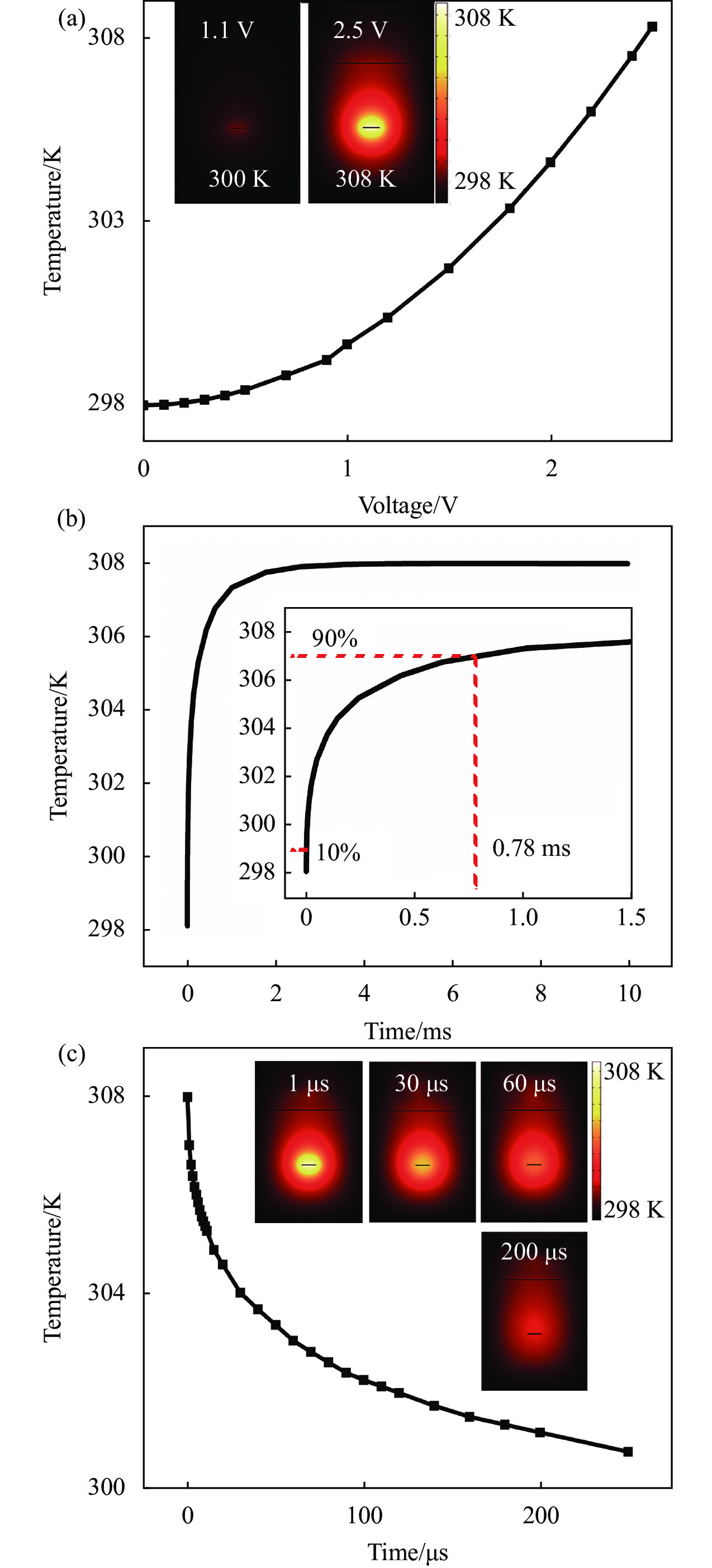
当不能满足最佳长度比时,利用LRSPP波导进行主动调谐,策略就是通过施加电压主动调节LRSPP波导的温度,以消除温度对相位的影响。LRSPP波导芯层材料为金,具有光电复用的特性,既能传输光,也是电的良导体,可通过电极直接将调谐电压施加到芯层上,利用热光效应改变LRSPP波导的传输特性,进而补偿温度对Si3N4波导的影响。当波导实际温度偏离设定工作温度时,由公式(2)可算得需要LRSPP波导的主动调谐量,进而得到LRSPP波导所需的升温或降温量。当需要LRSPP波导升温时,外加电压经电极加载到LRSPP波导芯层上,通过发热导致LRSPP波导温度上升,进而实现对相位的调谐。随着施加调制电压的升高,LRSPP波导的温度也越高,如图6(a)所示,其中2.5 V的电压就能实现10 ℃的升温。当向LRSPP波导芯层施加电压时,LRSPP波导的温度快速上升,随后上升速率减缓并逐步趋于稳定,达到所需的温度以实现温度不敏感,如图6(b)所示,可得升温的响应时间为0.78 ms。此外,根据对LRSPP施加的电压可得LRSPP波导升温1 ℃所需要的功率为0.45 mW。当需要LRSPP波导降温时,通过自然降温来实现,降温曲线如图6(c)所示,降温10 ℃仅需200 μs左右的时长,能迅速响应波导的调谐需求。

图 6 (a) LRSPP波导温度与施加电压的关系,插图是不同电压下LRSPP波导的温度场分布;(b) LRSPP波导的升温曲线,插图是升温曲线局部放大图;(c) LRSPP波导的降温曲线,插图是不同降温时间下LRSPP波导的温度场分布
Figure 6. (a) Temperature of the LRSPP waveguide under different voltages, inset: the temperature field distribution of the LRSPP waveguide under different voltages; (b) Heating curve of the LRSPP waveguide, inset: zoom in the heating curve; (c) Cooling curve of the LRSPP waveguide, inset: the temperature field distribution of the LRSPP waveguide
LRSPP波导为Si3N4波导的温度补偿提供了有效途径。进一步考虑到工程化应用,可构建自动伺服系统优化LRSPP波导的温度补偿过程,通过对波导输出的检测、比较、反馈、补偿实现对Si3N4波导的主动补偿。具体过程大致如下:在不满足最佳长度比的前提下,当环境温度发生变化时,检测波导的输出,并与设定工作温度下的输出进行比较,结合公式(2)求得需要LRSPP波导补偿的模式有效折射率,将此补偿量转化为芯层调制的电压,然后将电压施加于LRSPP波导的芯层上,构成伺服回路,实现对整个波导结构温度特性的主动补偿。
-
由于LRSPP波导仅支持TM偏振态工作,因此对于文中提出的混合波导结构,只有TM偏振态的光才能激励,具有良好的单偏振特性。为了研究LRSPP波导的偏振特性,搭建了如图7(a)所示的测试系统,测试LRSPP波导在不同偏振态下的传输特性。激光器产生1550 nm的激光,经偏振控制器后耦合进LRSPP波导,输出端接光功率计,检测输出光功率。通过偏振控制器调节输入光的偏振态,得到LRSPP波导在不同偏振态下的特性。图7(b)和7(c)分别为LRSPP波导在TM偏振态和TE偏振态下的输出。在TM偏振态下,LRSPP波导输出良好,输出光功率为−46 dBm;而在TE偏振态下几乎没有输出,输出光功率为−110 dBm(探测器探测光功率下限),由此计算得偏振消光比为64 dB,表明LRSPP波导具有良好的单偏振特性。
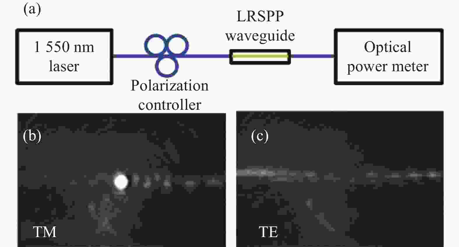
图 7 (a) LRSPP波导测试装置;(b) LRSPP波导在TM偏振态下的输出光斑;(c) LRSPP波导在TE偏振态下的输出
Figure 7. (a) Experimental setup of the LRSPP waveguide; (b) Output spot of the LRSPP waveguide at TM polarization state; (c) Output of the LRSPP waveguide under the TE polarization state
-
文中提出的基于Si3N4波导和LRSPP波导的温度不敏感混合结构,充分发挥了LRSPP波导负热光特性的优势,实现对器件性能随温度漂移的抑制和补偿。当LRSPP波导和Si3N4波导长度比为0.77时,实现温度不敏感;当无法满足温度不敏感的条件时,通过LRSPP芯层调制进行主动补偿。与采用外部温控装置改善器件温度特性的方式相比,基于Si3N4波导和LRSPP波导的温度不敏感混合波导结构具有可主动调谐、损耗低、单偏振、体积小、集成度高、普适性高等优点,能有效地解决器件性能随温度漂移的问题,提高集成光学器件和PICs的温度稳定性,从而进一步推动光子集成芯片的实用化和工程化。
Temperature-insensitive waveguide based on Si3N4 and LRSPP
-
摘要: 光子集成芯片将多种功能器件进行片上集成,具有损耗低、带宽大、抗电磁干扰等优势,是当前光电领域发展的主流方向。集成光学器件的温度稳定性是影响其光学性能的重要因素之一。为了提高集成光学器件温度稳定性,提出了基于氮化硅(Si3N4)和长程表面等离激元(Long-Range Surface Plasmon Polariton,LRSPP)波导的温度不敏感结构,对器件性能随温度的漂移进行抑制和补偿。首先,分析了Si3N4波导和LRSPP波导对接的模式耦合效率,当满足最佳匹配条件时,可实现耦合效率99.9%以上的高效耦合。对混合波导的温度特性进行了分析,结果表明,当LRSPP波导和Si3N4波导的最佳长度比为 0.077,相位不随温度的变化而发生漂移,实现了温度不敏感的波导。当波导不能满足最佳长度比时,对LRSPP波导芯层施加电压实现主动补偿,亦可实现温度不敏感。此外,对LRSPP波导的传输特性进行了测试,测得偏振消光比为64 dB,具有良好的单偏振特性。文中提出的温度不敏感结构具有可主动调谐、损耗低、单偏振、普适性高等优点,能有效地解决Si3N4波导性能随温度变化发生漂移的问题,在Si3N4基光子集成芯片中具有广泛的应用前景。Abstract:
Objective Photonic integrated circuits composed of a variety of integrated functional devices on one chip have become the mainstream of the photoelectric fields due to their low loss, large bandwidth, and anti-electromagnetic interference properties, which are widely applied in optical sensing, radar, photon computing and medical testing. Due to the inherent thermo-optic characteristics of optical waveguide materials, the refractive index of the core and cladding materials will change with the temperature fluctuation, leading to the temperature stability which is one of the main problems in the engineering application of the photonic integrated circuits. Therefore, it is necessary to suppress and compensate for the drift of optical device performance with temperature to improve the temperature stability of the photonic integrated circuits. In this respect, a temperature-insensitive hybrid structure based on silicon nitride and long-range surface plasmon polariton (LRSPP) waveguides was proposed to suppress and compensate for the performance drift caused by temperature variation. Methods For the studies of the proposed temperature insensitive hybrid waveguide based on silicon nitride and LRSPP, the propagation properties, temperature stability and polarization characteristics were investigated. Firstly, considering the coupling efficiency between silicon nitride waveguide and LRSPP waveguide, the propagation model of silicon nitride waveguide and SPP waveguide was established. The mode coupling efficiencies and the optical propagation filed under different waveguide sizes were analyzed by using the finite difference time domain method. Then, the temperature stability was analyzed by the calculation of the phase change when the temperature fluctuated. Moreover, the polarization properties of the fabricated LRSPP waveguide were measured by the output spot and optical power under the transverse magnetic (TM) and the transverse electric (TE) mode. Results and Discussions The mode coupling efficiencies between the silicon nitride waveguide and LRSPP waveguide were more than 99.9% in the optimal cases (Fig.3), resulting in the almost negligible coupling losses. What's more, the proposed hybrid waveguide still showed good propagation characteristics even with 100 nm offset in vertical direction between the silicon nitride waveguide and LRSPP waveguide (Fig.4). For the temperature characteristics of the hybrid waveguide, there was an optimal length ratio of the LRSPP and silicon nitride waveguide for the defined waveguide to realize temperature insensitivity. Specifically, when the thermo-optic coefficient of the LRSPP waveguide was −1.86×10⁻⁴/℃, the optimal length ratio was 0.077, leading to zero phase drift when the temperature changes (Fig.5). However, when the optimal length ratio is not met, the hybrid waveguide can still achieve temperature insensitivity through the active phase compensation performed by the core modulation of the LRSPP waveguide. When a voltage signal was applied directly to the core layer of the LRSPP waveguide, the temperature of the LRSPP waveguide rose and gradually stabilized to the required temperature to compensate for the temperature drift (Fig.6). A voltage of 2.5 V can achieve a temperature rise of 10 °C with the response time of 0.78 ms, which can quickly respond to the tuning needs of the waveguide, resulting in high tuning efficiency. In addition, since the LRSPP waveguide only supports TM polarization state, the proposed hybrid waveguide inherited the single-polarization characteristic. In the TM polarization state, the output of the LRSPP waveguide is good with the output optical power of −46 dBm. While in the TE polarization state there is almost no output and the output optical power is −110 dBm (the lowest detection limit of the detector) (Fig.7). Accordingly, the polarization extinction ratio was calculated as 64 dB, indicating that the LRSPP waveguide has good single-polarization characteristics. Conclusions From the perspective of the basic waveguide, the proposed temperature-insensitive hybrid waveguide has the benefits of active tuning, low loss, single polarization and high universality, which can effectively address the performance drift of the silicon nitride waveguide caused by the temperature change and has broad application prospects in silicon-nitride-based photonic integrated circuits. -
图 1 (a) SiO2波导的TM模;(b) SOI波导的TM模;(c) Si3N4波导的TM模;(d) LRSPP波导的TM模
Figure 1. TM mode of (a) SiO2 waveguide; (b) SOI waveguide; (c) Si3N4 waveguide; (d) LRSPP waveguide
图 2 (a) 基于Si3N4和LRSPP波导的温度不敏感结构示意图;(b) Si3N4波导横截面;(c) LRSPP波导横截面
Figure 2. (a) Schematic diagram of temperature insensitive structure based on Si3N4 waveguide and LRSPP waveguide; (b) Cross-section of the Si3N4 waveguide; (c) Cross-section of the LRSPP waveguide
图 3 (a) Si3N4波导和LRSPP波导的耦合效率与波导厚度的关系,插图是耦合效率的局部放大图;(b) Si3N4波导和LRSPP波导的耦合效率与波导宽度的关系,插图是最佳耦合效率下波导的厚度关系图;(c) Si3N4波导和LRSPP波导的模式面积差与波导厚度的关系;(d) Si3N4波导和LRSPP波导的耦合损耗与波导厚度的关系
Figure 3. (a) Coupling efficiencies of the Si3N4 waveguide and LRSPP waveguide with different core heights. Inset: the zoom of the coupling efficiency; (b) Coupling efficiencies of the Si3N4 waveguide and LRSPP waveguide with different core widths. Inset: optimal coupling efficiency with different core heights; (c) Mode area differences of the Si3N4 waveguide and LRSPP waveguide with different core heights; (d) Coupling losses of the Si3N4 waveguide and LRSPP waveguide with different core heights
图 4 (a) Si3N4波导和LRSPP波导在横向(x方向)和纵向(y方向)上的偏移;(b) Si3N4波导和LRSPP波导横向偏移时的传输场;(c)~(g) Si3N4波导和LRSPP波导在不同纵向偏移时的特性:(i) P1点的模式分布,(ii) P2的模式分布,(iii)传输场
Figure 4. (a) Offset between the Si3N4 waveguide and LRSPP waveguide in horizontal (x) and vertical (y) direction; (b) Transmission field of the Si3N4 waveguide and LRSPP waveguide with lateral offset; (c)-(g) Properties of the Si3N4 waveguide and LRSPP waveguide with longitudinal offset: (i) mode distribution in P1, (ii) mode distribution in P2, (iii) transmission field
图 5 (a) Si3N4波导和LRSPP波导模式有效折射率随温度的变化曲线;(b) 不同热光系数下,相位变化与Si3N4波导和LRSPP波导长度比的关系
Figure 5. (a) Effective mode refractive index of the Si3N4 waveguide and LRSPP waveguide under different temperatures; (b) Phase change of the Si3N4 waveguide and LRSPP waveguide under different length ratios
图 6 (a) LRSPP波导温度与施加电压的关系,插图是不同电压下LRSPP波导的温度场分布;(b) LRSPP波导的升温曲线,插图是升温曲线局部放大图;(c) LRSPP波导的降温曲线,插图是不同降温时间下LRSPP波导的温度场分布
Figure 6. (a) Temperature of the LRSPP waveguide under different voltages, inset: the temperature field distribution of the LRSPP waveguide under different voltages; (b) Heating curve of the LRSPP waveguide, inset: zoom in the heating curve; (c) Cooling curve of the LRSPP waveguide, inset: the temperature field distribution of the LRSPP waveguide
-
[1] Tran M A, Zhang C, Morin T J, et al. Extending the spectrum of fully integrated photonics to submicrometre wavelengths [J]. Nature, 2022, 610: 54-60. doi: 10.1038/s41586-022-05119-9 [2] 李明, 郝腾飞, 潘时龙, 等. 微波光子集成及前沿展望(特邀)[J]. 红外与激光工程, 2021, 50(07): 32-45. doi: 10.3788/IRLA20211048 Li Ming, Hao Tengfei, Pan Shilong, et al. Frontiers and prospects of integrated microwave photonics (Invited) [J]. Infrared and Laser Engineering, 2021, 50(7): 20211048. (in Chinese) doi: 10.3788/IRLA20211048 [3] 陈宏伟, 杜振民, 符庭钊, 等. 硅基光子集成宽带大色散延时芯片(特邀)[J]. 红外与激光工程, 2021, 50(07): 19-23. doi: 10.3788/IRLA20211045 Chen Hongwei, Du Zhenmin, Fu Tingzhao, et al. Wideband large dispersion group delay chip based on silicon photonics integration (Invited) [J]. Infrared and Laser Engineering, 2021, 50(7): 20211045. (in Chinese) doi: 10.3788/IRLA20211045 [4] Xue X, Tang J, Zhou H, et al. All-polymer monolithic resonant integrated optical gyroscope [J]. Optics Express, 2022, 30: 42728-42737. doi: 10.1364/OE.474447 [5] Nejadriahi H, Friedman A, Sharma R, et al. Thermo-optic properties of silicon-rich silicon nitride for on-chip applications [J]. Optics Express, 2020, 28: 24951-24960. doi: 10.1364/OE.396969 [6] Stern B, Kim K, Gariah H, et al. Athermal silicon photonic wavemeter for broadband and high-accuracy wavelength measurements [J]. Optics Express, 2021, 29: 29946-29959. doi: 10.1364/OE.432588 [7] Zhang X, Zhang T, Hu A, et al. Tunable microring resonator based on dielectric-loaded surface plasmon polariton waveguides [J]. Journal of Nanoscience and Nanotechnology, 2011, 11(12): 10520-10524. doi: 10.1166/jnn.2011.4094 [8] Yang Z, Wang Z, Zhang R, et al. Athermal chalcogenide microresonator cladded with polymer [J]. IEEE Photonics Journal, 2022, 14(5): 1-5. doi: 10.1109/JPHOT.2022.3203731 [9] He L, Guo Y, Han Z, et al. Broadband athermal waveguides and resonators for datacom and telecom applications [J]. Photonics Research, 2018, 6: 987-990. doi: 10.1364/PRJ.6.000987 [10] Tao S, Huang Q, Zhu L, et al. Athermal 4-channel (de-) multiplexer in silicon nitride fabricated at low temperature [J]. Photonics Research, 2018, 6: 686-691. doi: 10.1364/PRJ.6.000686 [11] Tang L, Li Y, Li J, et al. Temperature-insensitive Mach–Zehnder interferometer based on a silicon nitride waveguide platform [J]. Optics Letters, 2020, 45: 2780-2783. doi: 10.1364/OL.394143 [12] Guillén-Torres M, Almarghalani M, Sarraf E, et al. Silicon photonics characterization platform for gyroscopic devices[C]//Proc of SPIE, Photonics North, 2014, 9288: 92880U. [13] Aguiar D, Annoni A, Peserico N, et al. Automated tuning, control and stabilization of photonic integrated circuits[C]//Proc of SPIE, Integrated Optics: Physics and Simulations III, 2017, 10242: 1024208. [14] Berini P, de Leon I. Surface plasmon-polariton amplifiers and lasers [J]. Nature Photonics, 2012, 6: 16-24. doi: 10.1038/nphoton.2011.285 [15] Qian G, Fu X, Zhang L, et al. Hybrid fiber resonator employing LRSPP waveguide coupler for gyroscope [J]. Scientific Reports, 2017, 7: 41146. doi: 10.1038/srep41146 [16] Su Y, Zhang Y, Qiu C, et al. Silicon photonic platform for passive waveguide devices: materials, fabrication, and applications [J]. Advanced Materials Technologies, 2020, 5: 1901153. doi: 10.1002/admt.201901153 [17] Zhang L, Hong S, Wang Y, et al. Ultralow-loss silicon photonics beyond the singlemode regime [J]. Laser & Photonics Reviews, 2022, 16: 2100292. doi: 10.1002/lpor.202100292 [18] Butt M, Tyszkiewicz C, Karasiński P, et al. Optical thin films fabrication techniques—Towards a low-cost solution for the integrated photonic platform: A review of the current status [J]. Materials, 2022, 15: 4591. doi: 10.3390/ma15134591 [19] Bauters J, Heck M J R, Dai D, et al. Ultralow-loss planar Si3N4 waveguide polarizers [J]. IEEE Photonics Journal, 2013, 5(1): 6600207. doi: 10.1109/JPHOT.2012.2234095 -

 点击查看大图

计量
- 文章访问数: 71
- HTML全文浏览量: 26
- PDF下载量: 19
- 被引次数: 0

