


-
相移轮廓术(Phase Shifting Profilometry, PSP)是当前最常用的三维测量技术之一,具有精度高、鲁棒性强以及全场测量等优点[1-4]。在PSP重建过程中,需要投影仪投射至少三幅具有相移的正弦条纹图到物体表面,并由相机从另一个角度进行拍摄。物体表面反射的条纹图因物体高度产生扭曲,基于正弦条纹图中的相位信息分析条纹形变,最后根据相位信息和系统参数(相机、投影仪内参和外参)实现三维重构,由于使用了多张条纹图,传统的PSP算法要求物体在重构过程中必须保持静止。物体一旦在条纹投射和捕获过程中发生移动,则会产生测量误差。
近年来,运动物体的三维测量引起了广泛关注[5]。Liu等[6]、Wei等[7]、Lv等[8-9]提出一种基于物体运动跟踪的运动误差补偿方法。通过计算机视觉技术对物体运动进行跟踪,并获得描述物体运动的旋转平移矩阵,最终基于物体运动引起的相移补偿运动误差。Liu等[10]提出了一种减少PSP运动误差的方法。首先估计相邻帧三维数据之间的运动信息,进而分析运动引起的相位变化,最终基于迭代算法获得精确的运动物体的三维信息。Guo等[11]基于四步PSP提出了一种消除物体运动误差的实时方法。四幅条纹图被分为了两组,并分别计算包裹相位。由于运动误差频率是条纹频率的两倍,两组包裹相位中的运动误差正好可以相互抵消。Wu等[12]提出了基于希尔伯特变换跟踪物体运动的方法。首先基于希尔伯特变换抑制条纹图的低频分量,然后使用滤波器去除图像噪声,得到无条纹的图像,最终分析得到物体的运动信息并完成运动误差补偿。Feng等[13]、Qian等[14]、Yu等[15]利用深度学习从单个条纹图中获得高精度相位。基于深度学习的三维重建方法可以实现单帧图像对动态场景的三维测量。然而,深度学习的网络训练耗时长,难以实现实时处理。Wang等[16]提出一种附加时间采样的运动误差补偿方法,该方法在每个条纹图案照明周期内采集两次条纹图,并基于物体运动匀速的假设利用两组条纹图进行运动误差补偿。
针对运动物体的三维测量,在相机和投影仪速度受限的条件下,高帧率意味着获取到更多运动物体信息。一般情况下,投影仪投射8位条纹图案的帧率可达120 Hz,而相机帧率较容易达到1000 Hz以上。因此,重构的点云帧率易受投影仪速率的限制。通过散焦技术,投影仪投射二进制条纹图得到正弦波条纹图的帧率可达到1000 Hz以上,但散焦的程度难以控制和量化。高速相机和投影仪能达到高帧率的目的,但成本会显著增加[17]。因此,如何利用低成本设备进行运动物体高帧率三维重构是亟待解决的问题。
文中提出了一种基于相移轮廓术的双采样运动物体三维重构方法。首先,在相机和投影仪之间增加触发控制设备,使投影仪每投一幅条纹图像,相机进行两次拍摄,采集更多运动物体的条纹信息;然后,分析连续3张条纹图中物体运动和相位变化,得到包含物体运动的条纹模型,进而正确提取运动物体相位信息,最终结合系统参数实现运动物体高精度三维重构。
-
假设使用$ N $步相移轮廓术,相机拍摄到的条纹图可分别表示为:
$$ {I_n}(x,y) = a + b\cos \left[\phi (x,y) + \varphi (x,y) + \frac{{2\pi (n - 1)}}{N}\right] $$ (1) 式中:$ {I_n}(x,y) $为条纹图的强度分布; $n = 1,2,\cdots; N$为条纹图序号;$ a $为环境光强度;$ b $为条纹图的振幅调制;$ \phi (x,y) $为参考平面的相位分布;$ \varphi (x,y) $为物体形状引起的相位变化。
物体相位分布可通过公式(2)计算获得:
$$ \phi \left( {x,y} \right) + \varphi (x,y) = \arctan \frac{{ - \displaystyle\sum\limits_{n = 1}^N {I_n\left( {x,y} \right)\sin 2\pi \left( {n - 1} \right)/N} }}{{\displaystyle\sum\limits_{n = 1}^N {I_n^{}\left( {x,y} \right)\cos 2\pi \left( {n - 1} \right)/N} }} $$ (2) 由于使用了反正切函数$ \arctan ( \cdot ) $,公式(2)计算得到的相位值被包裹在$ [ - \pi ,\pi ] $中。为得到物体条纹图与投射条纹图之间的对应关系,需使用解包裹算法[18]将重复且有歧义的包裹相位进行解包裹,得到连续单调的解包裹相位,进而基于系统参数完成三维重构。
-
为重构运动物体并获取更多的运动信息,提高运动物体三维重构帧率,在投影仪帧率受限的前提下,相机在一幅投射条纹内采集两次运动物体条纹信息。其时序如图1所示。

图 1 双采样条纹捕获机制
Figure 1. Triggers between camera and projector
图1中,投影仪按一定速率正常投射N幅条纹图,在一幅投影周期内触发相机两次,完成双采样条纹捕获,获取丰富的运动物体信息。如$ I_1^c $和$ I_{\text{2}}^c $为在投射条纹$ I_1^p $时连续拍摄的两幅条纹图;$ I_{\text{3}}^c $和$ I_{\text{4}}^c $为在投射条纹$ I_{\text{2}}^p $时捕获的条纹图。其中,同一个投射条纹下拍摄的两张条纹图中仅存在因物体运动引起的相移(如$ I_1^c $和$ I_{\text{2}}^c $);而不同投射条纹下拍摄的条纹图中既存在物体运动引起的相移,又存在PSP方法的传统相移。因此,若需基于$ I_1^c $、$ I_{\text{2}}^c $和$ I_{\text{3}}^c $ 3幅条纹图进行相位提取,则需分析混合相移情况下的相位变化。
通过分析物体运动对相位分布的影响[19],包含运动信息的$ I_1^c $、$ I_{\text{2}}^c $和$ I_{\text{3}}^c $可表示为:
$$\begin{split}& I_1^c(x,y) = a + b\cos \{\phi [{f_1}(x,y),{g_1}(x,y)] + \varphi (x,y) + {\delta _{\text{1}}}\} \\& I_2^c(x,y) = a + b\cos \{\phi [{f_{\text{2}}}(x,y),{g_{\text{2}}}(x,y)] + \varphi (x,y) + {\delta _{\text{2}}}\} \\& I_3^c(x,y) = a + b\cos \{\phi [{f_{\text{3}}}(x,y),{g_{\text{3}}}(x,y)] + \varphi (x,y) + {\delta _{\text{3}}}\} \end{split} $$ (3) 式中:$ {\delta _{\text{1}}} $、$ {\delta _{\text{2}}} $和$ {\delta _{\text{3}}} $为相移量且$ {\delta _{\text{1}}} = {\delta _{\text{2}}} = {\text{0}} $,$ {\delta _{\text{3}}} = {{2\pi } \mathord{\left/ {\vphantom {{2\pi } N}} \right. } N} $;$[{f_n}(x,y),{g_n}(x,y)]$表示物体运动前后的坐标变换关系,可由描述物体运动的旋转平移矩阵得到。
将公式(3)改写为:
$$ \begin{split} I_{\text{1}}^c(x,y) =& a + B(x,y)\cos\{\phi [{f_1}(x,y),{g_1}(x,y)] + {\delta _{\text{1}}}\} + \\& C(x,y)\sin \{\phi [{f_1}(x,y),{g_1}(x,y)] + {\delta _{\text{1}}}\} \\ I_{\text{2}}^c(x,y) =& a + B(x,y)\cos \{\phi [{f_{\text{2}}}(x,y),{g_{\text{2}}}(x,y)] + {\delta _{\text{2}}}\} +\\& C(x,y)\sin \{\phi [{f_2}(x,y),{g_2}(x,y)] + {\delta _{\text{2}}}\} \\ I_{\text{3}}^c(x,y) =& a + B(x,y)\cos \{\phi [{f_{\text{3}}}(x,y),{g_{\text{3}}}(x,y)] + {\delta _{\text{3}}}\} + \\& C(x,y)\sin \{\phi [{f_{\text{3}}}(x,y),{g_{\text{3}}}(x,y)] + {\delta _{\text{3}}}\} \end{split} $$ (4) 其中
$ B(x,y) = \cos \varphi (x,y) $; $ C(x,y) = {{ - }}\sin \varphi (x,y) $。将公式(4)用一般通用形式表示:
$$ I_n^c(x,y) = a + B(x,y)\cos ({h_n}) + C(x,y)\sin ({h_n}) $$ (5) 式中:${h_n} = \phi [{f_n}(x,y),{g_n}(x,y)] + {\delta _n}$。假设拍摄到的真实条纹图表示为$ \tilde I_n^c $,则可定义误差目标方程为:
$$ S(x,y) = \sum\limits_{n = 1}^N {{{(\tilde I_n^c - I_n^c)}^2}} $$ (6) 基于最小二乘准使公式(6)最小,可得:
$${\boldsymbol G}(x,y) = {{\boldsymbol A}^{ - 1}}(x,y)X(x,y) $$ (7) 其中
$$ {\boldsymbol{A}}(x,y) = \left[ {\begin{array}{*{20}{c}} N&{\displaystyle\sum\limits_{n = 1}^N {\cos ({h_n})} }&{\displaystyle\sum\limits_{n = 1}^N {\sin ({h_n})} } \\ {\displaystyle\sum\limits_{n = 1}^N {\cos ({h_n})} }&{\displaystyle\sum\limits_{n = 1}^N {{{\cos }^{\text{2}}}({h_n})} }&{\dfrac{1}{2}\displaystyle\sum\limits_{n = 1}^N {\sin ({\text{2}}{h_n})} } \\ {\displaystyle\sum\limits_{n = 1}^N {\sin ({h_n})} }&{\dfrac{1}{2}\displaystyle\sum\limits_{n = 1}^N {\sin ({\text{2}}{h_n})} }&{\displaystyle\sum\limits_{n = 1}^N {{{\sin }^{\text{2}}}({h_n})} } \end{array}} \right] $$ (8) $$ {\boldsymbol{G}}(x,y) = {\left[ {\begin{array}{*{20}{c}} a&{B(x,y)}&{C(x,y)} \end{array}} \right]^{\rm T}} $$ (9) $$ \begin{split}&{\boldsymbol{X}}(x,y) =\\& {\left[ {\begin{array}{*{20}{c}} {\displaystyle\sum\limits_{n = 1}^N {\tilde I_n^c(x,y)} }&{\displaystyle\sum\limits_{n = 1}^N {\tilde I_n^c(x,y)\cos ({h_n})} }&{\displaystyle\sum\limits_{n = 1}^N {\tilde I_n^c(x,y)\sin ({h_n})} } \end{array}} \right]^{\rm T}} \end{split}$$ (10) 通过求解公式(7)~(10)可得到$ a $、$ B(x,y) $和$ C(x,y) $之间的关系,进而可得到相位$ \varphi (x,y) $:
$$ \varphi (x,y) = \arctan [ - C(x,y)/B(x,y)] $$ (11) 为提高重构点云的帧率,可对双采样获取到的条纹图进行复用,并基于上述方法进行重构。其时序图如图2(b)所示。

图 2 条纹图案投影策略。 (a) 使用传统PSP的重构帧率; (b) 文中提出的方法的重构帧率
Figure 2. Strategies for fringe pattern projection. (a) The reconstructed frame rate using traditional PSP; (b) The reconstructed frame rate of the method proposed in this paper
-
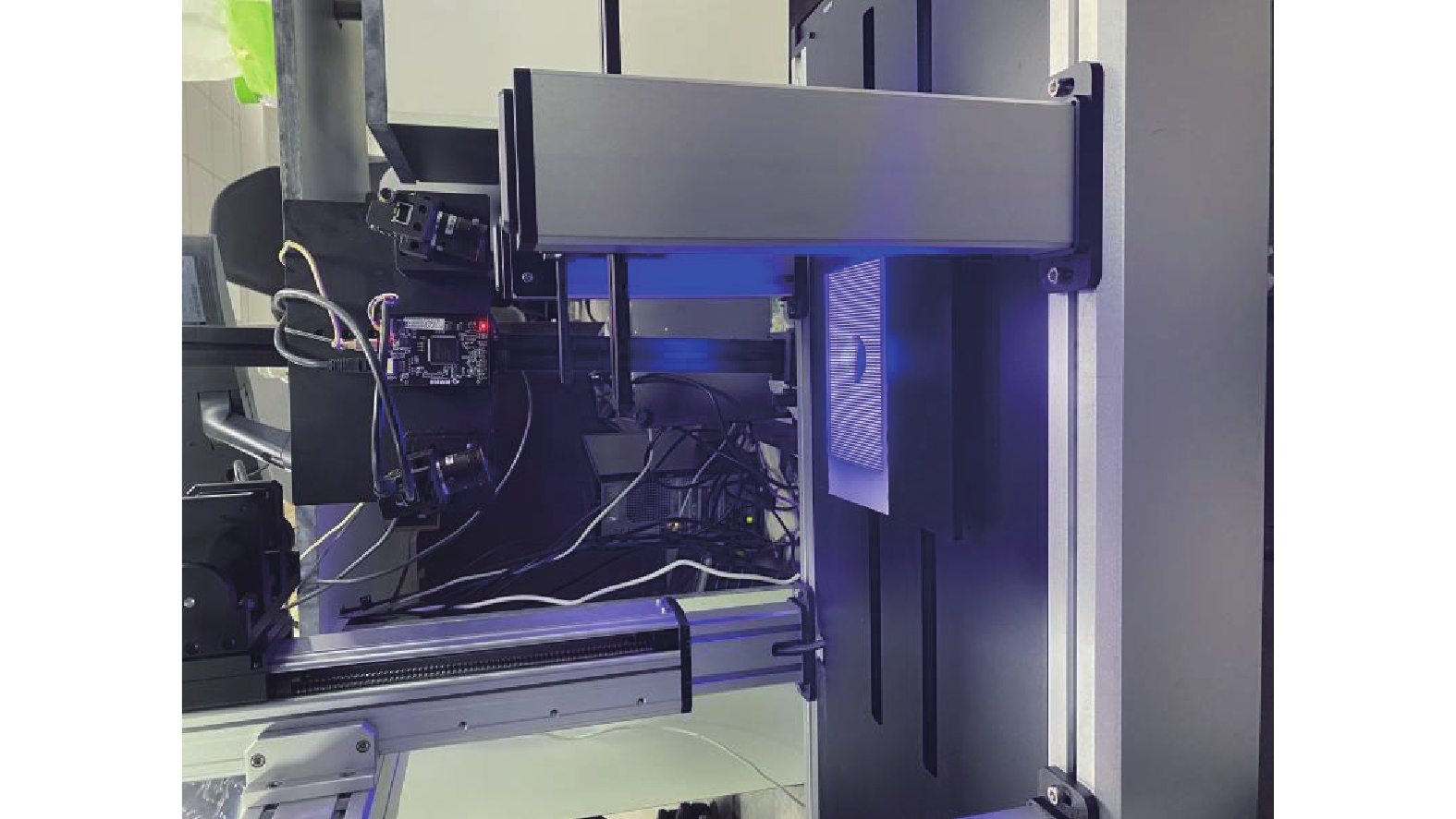
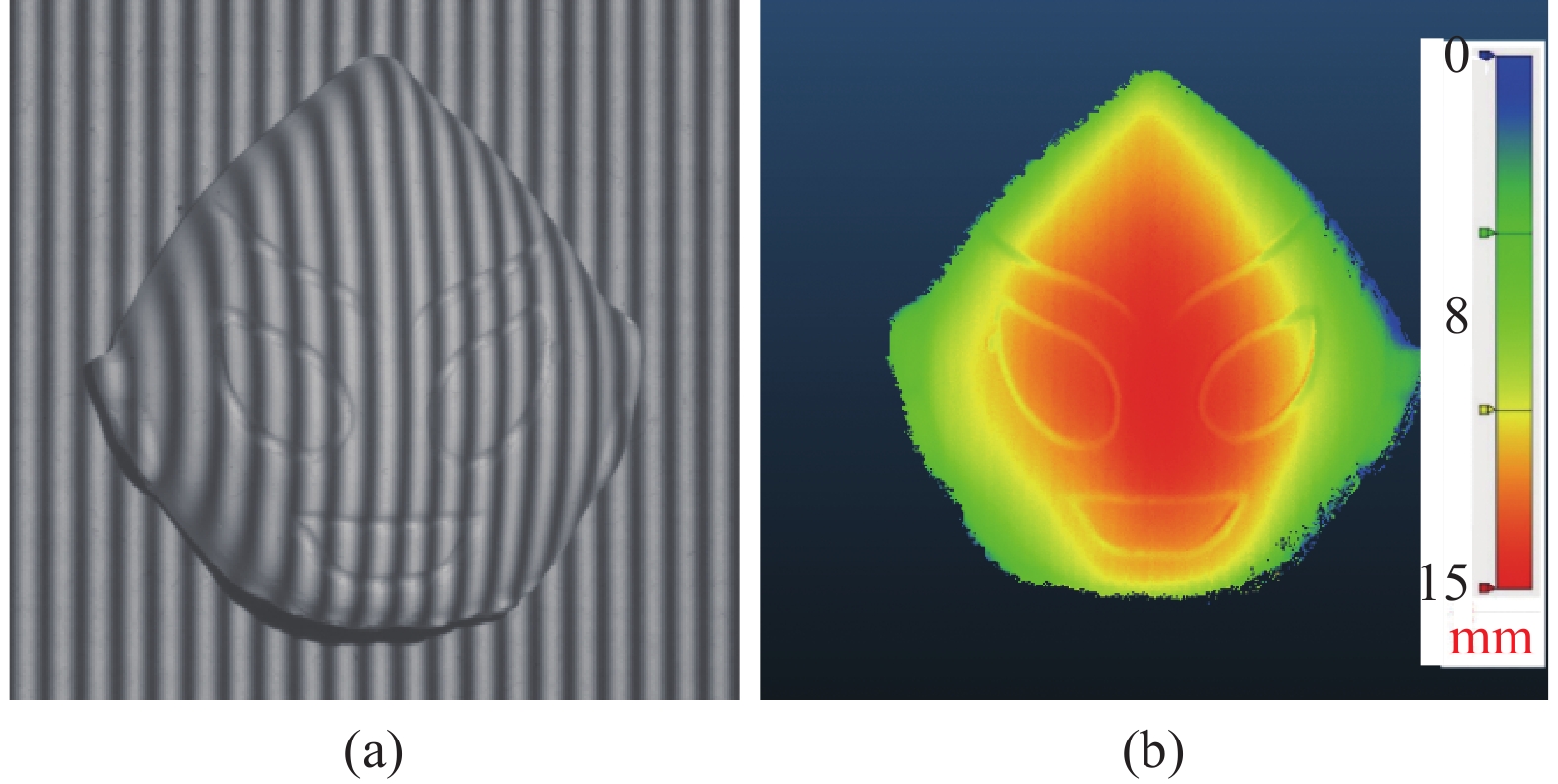
文中实验系统采用了工业相机(OPT-CC1-048 A-RM-G,分辨率1800 pixel×1600 pixel)、投影仪(TJ-S50,分辨率1280 pixel×720 pixel)和电动位移台(如图3所示)。被测物体为面具,该实验中相机的帧率为20 帧/s,位移台速率为20 mm/s,设备视场为70 mm×80 mm。包含相移的条纹图被连续投射到物体上,其物体条纹图如图4(a)所示,物体静止时重构的结果如图4(b)所示。

图 3 单目三维测量系统图
Figure 3. Diagram of monocular 3D measurement system

图 4 使用传统PSP重构静止物体。(a)拍摄到的物体条纹图;(b)重构结果
Figure 4. Reconstructing stationary objects using traditional PSP. (a) The captured fringe pattern; (b) Reconstructing results
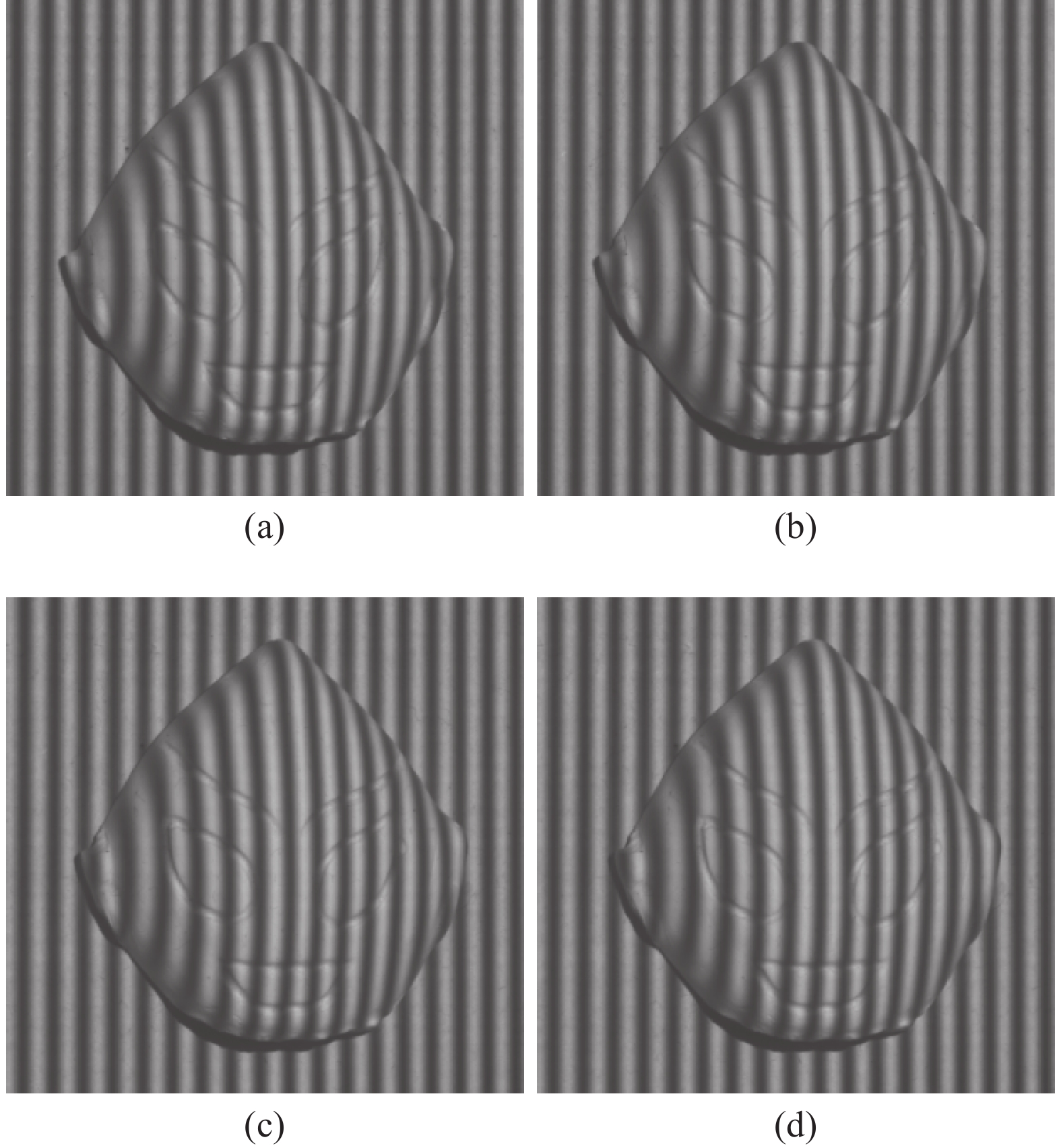
当物体被放在位移台上进行运动时,其被拍到的条纹图如图5所示。其中,图5(a)、(b)为第一幅投射图像时双采样拍摄到的两张图片。图5(c)、(d)为投射第二幅图像时采集到的两张图片。可以看出,在同一幅投射条纹图中采集的图片中仅包含物体运动,而不同投射条纹图之间采集的图片中既包含物体运动,又包含条纹相移。
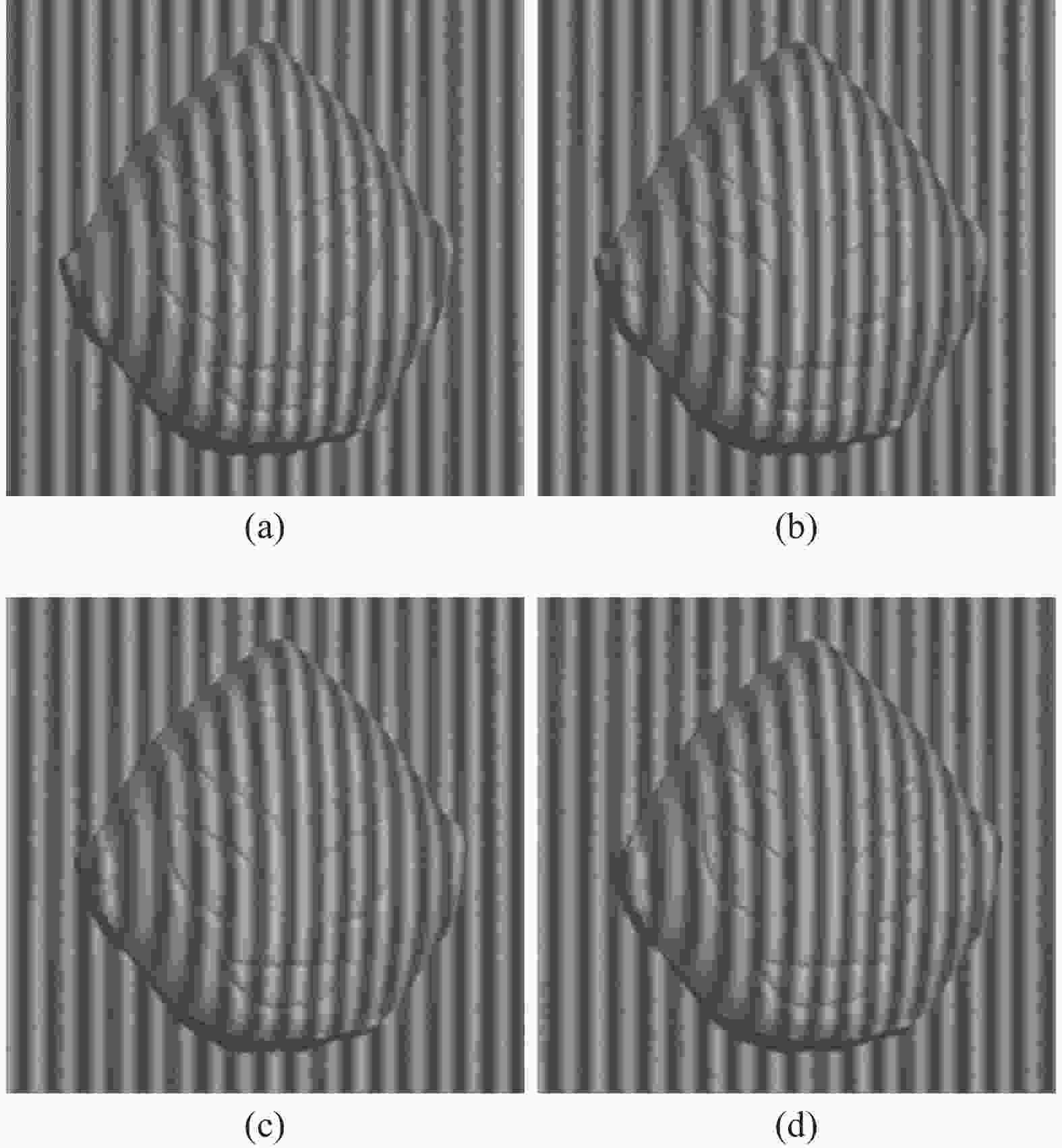
图 5 运动物体条纹图。(a)投影仪投射第一张条纹时相机拍摄到的第一张条纹图; (b)投影仪投射第一张条纹时相机拍摄到的第二张条纹图; (c)投影仪投射第二张条纹时相机拍摄到的第一张条纹图; (d)投影仪投射第二张条纹时相机拍摄到的第二张条纹图
Figure 5. Fringe pattern during object movement. (a) The first fringe pattern taken by the camera when the projector projects the first stripe; (b) The second fringe pattern taken by the camera when the projector projects the secnod stripe; (c) The first fringe pattern taken by the camera when the projector projects the second stripe; (d) The second fringe pattern taken by the camera when the projector projects the second stripe
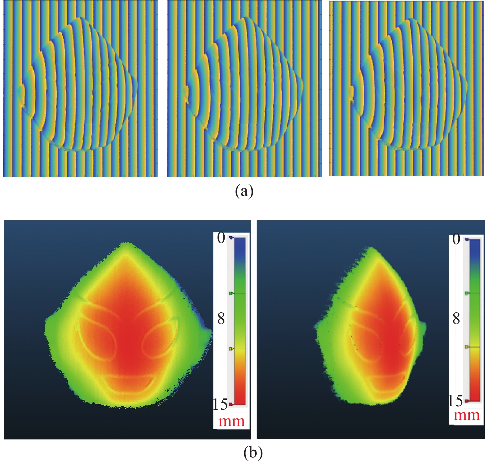
通过物体运动跟踪[20]算法计算描述物体运动的旋转平移矩阵,进而使用文中方法提取物体相位。为了提高物体帧率,所拍摄条纹图将被用来复用,每三幅相邻图像可得出一帧物体相位,并实现高帧率三维重构。条纹图复用得到的多个包裹相位分布如图6(a)所示,最终重构结果如图6(b)所示。
为了对比文中算法的重构效果,基于传统相移轮廓术对运动物体进行了重构,其结果如图7所示,可明显看出结果中存在较大误差。
以物体静止时的测量结果为真值量化评估了所提出方法的精度,分析了物体运动情况下文中算法和传统相移轮廓术的误差,如表1所示。使用传统相移轮廓术测量运动物体时,其均方根(RMS)为4.9775 mm,均值(mean)为0.1575 mm。使用文中方法时,其均方根为0.0029 mm,均值为0.0344 mm,进一步验证了文中方法的有效性。

图 6 使用文中所提出方法重构运动物体。(a)条纹图复用得到不同位置的相位图;(b)重构结果
Figure 6. Reconstruction result of moving objects using the proposed method. (a) Phase diagram obtained by repeating frame rate; (b) Reconstructing results

图 7 使用传统PSP重构运动物体
Figure 7. Reconstructing moving objects using traditional PSP
表 1 测量误差
Table 1. Measurement error evaluation
Method Mean error/mm RMS error/mm Tradition PSP 0.1575 4.9775 Proposed method 0.0344 0.0029 实验结果表明,文中提出的方法能在设备帧率有限的基础上提高运动物体的重构帧率。但也存在一定的局限性,其中影响最大的是物体跟踪算法的精度,该精度直接影响重构精度,现有物体跟踪算法难于进行大幅度的运动描述。因此,如何提升物体跟踪算法的精度是未来值得深究的问题。
文中算法仅可重构包含二维平移运动的物体,鉴于运动跟踪算法的局限,无法处理二维旋转运动和三维运动。在物体运动速度方面不要求物体为匀速运动,但相机需拍摄到清晰的运动物体条纹图像。
-
文中提出了一种基于相移轮廓术的双采样运动物体重构方法。在设备帧率受限的条件下,可有效提高运动物体的重构帧率。首先通过控制相机和投影仪的同步信号,实现在同一幅投射条纹图中拍摄两次,获取更多运动物体的信息。然后分析了运动物体的条纹描述,并提取了混合相移情况下的相位信息;最终利用条纹复用提高了运动物体重构帧率。
3D reconstruction of the moving object with double-shooting based on phase shifting profilometry
-
摘要: 相移轮廓术因其高精度和高鲁棒性广泛应用于三维重构。由于需投射多幅条纹图到物体表面,相移轮廓术要求物体在重构过程中保持静止,导致运动物体的三维重构精度较低。文中提出了一种基于相移轮廓术的双采样运动物体三维重构方法。首先调整相机和投影仪时序,使投影仪投射一幅条纹图的同时,相机完成两次采集。然后分析物体运动对双采样条纹图的影响,并建立条纹描述方程。结合物体的运动信息,提取混合相移条纹图中的相位信息。最终对拍摄条纹图进行复用,提高运动物体的三维重构帧率。实验结果表明,该方法不仅可以精确重构运动物体,减少运动误差,还在投影速度受限的前提下提高了运动物体的三维重构帧率。Abstract:
Objective Phase shifting profilometry (PSP) is one of the most commonly used techniques in 3D measurement, which has the advantages of high accuracy and robustness to ambient light and reflectivity variation. During the reconstruction of PSP, at least three sinusoidal fringe patterns with phase shift are projected onto the surface of the object; the camera captures the ones reflected from the object. Because of the height of the object, the fringe patterns on the object surface will have distortions. The phase information existing in the fringe pattern is employed to analyze the deformation of the fringe patterns. At last, the object is reconstructed based on the phase information and system parameters. Because of multiple fringe patterns are used, the traditional PSP requires the object must be kept stationary during the reconstruction process. Errors will occur if the object moves during the fringe projecting and capture process. However it is difficult to meet this requirement in dynamic scenes. Therefore, it is important to improve the reconstruction accuracy of moving object. For this purpose, a new method with high frame rate and accuracy is proposed based on PSP. Methods This paper proposes a new method to reduce the measurement error caused by moving objects at dense frame rate. First of all, trigger control equipment is added to the camera and projector. The equipment ensures that, for each projection, two consecutive images are captured before the next projection (Fig.1). Then, the phase retrieval algorithm is proposed. As there is no fringe pattern shift among the captured two images of the same projection, the phase shift is introduced by the object motion. By analyzing the phase variation caused by the motion, the reconstruction model describing the fringe patterns with motion is given. At last, the object is reconstructed based on the phase information and system parameters. The proposed algorithm can achieve high frame rate for the reconstruction of object with motion (Fig.2). Results and Discussions The experiments are implemented to verify the performance of the proposed method. The moving object is captured twice in one projecting period (Fig.5). Then, the phase information is retrieved by the proposed method (Fig.6(a)). At last, the object is reconstructed successfully (Fig.6(b)). In order to compare the performance, the same fringe patterns are reconstructed by the traditional PSP and the result is shown in Fig.7. It is apparent that errors have been introduced. By using the data obtained with the static object as true value, the RMS error and mean error are calculated (Tab.1). With the traditional PSP, the RMS error and mean error are 4.918 6 mm and −0.085 1 mm. With the proposed method, the RMS error and mean error are 0.001 9 mm and 0.003 6 mm. Conclusions This article proposes a dual sampling method for reconstructing moving objects based on phase-shifting profilometry. Under the condition of limited device frame rate, the reconstruction frame rate of moving objects can be effectively improved. Firstly, by controlling the synchronization signal between the camera and projector, it is possible to capture the same projected fringe pattern twice to obtain more object motion information. Then, the stripe description of the moving object was analyzed and the phase information under mixed phase shift was extracted; Finally, utilizing stripe multiplexing improved the frame rate of motion object reconstruction. -
Key words:
- phase shifting profilometry /
- dynamic measurement /
- 3D reconstruction /
- high frame rate
-
图 2 条纹图案投影策略。 (a) 使用传统PSP的重构帧率; (b) 文中提出的方法的重构帧率
Figure 2. Strategies for fringe pattern projection. (a) The reconstructed frame rate using traditional PSP; (b) The reconstructed frame rate of the method proposed in this paper
图 4 使用传统PSP重构静止物体。(a)拍摄到的物体条纹图;(b)重构结果
Figure 4. Reconstructing stationary objects using traditional PSP. (a) The captured fringe pattern; (b) Reconstructing results
图 5 运动物体条纹图。(a)投影仪投射第一张条纹时相机拍摄到的第一张条纹图; (b)投影仪投射第一张条纹时相机拍摄到的第二张条纹图; (c)投影仪投射第二张条纹时相机拍摄到的第一张条纹图; (d)投影仪投射第二张条纹时相机拍摄到的第二张条纹图
Figure 5. Fringe pattern during object movement. (a) The first fringe pattern taken by the camera when the projector projects the first stripe; (b) The second fringe pattern taken by the camera when the projector projects the secnod stripe; (c) The first fringe pattern taken by the camera when the projector projects the second stripe; (d) The second fringe pattern taken by the camera when the projector projects the second stripe
图 6 使用文中所提出方法重构运动物体。(a)条纹图复用得到不同位置的相位图;(b)重构结果
Figure 6. Reconstruction result of moving objects using the proposed method. (a) Phase diagram obtained by repeating frame rate; (b) Reconstructing results
表 1 测量误差
Table 1. Measurement error evaluation
Method Mean error/mm RMS error/mm Tradition PSP 0.1575 4.9775 Proposed method 0.0344 0.0029  下载: 导出CSV
-
[1] Wang Z. Review of real-time three-dimensional shape measure-ment techniques [J]. Measurement, 2020, 156: 107624. doi: 10.1016/j.measurement.2020.107624 [2] Zuo C, Feng S, Huang L, et al. Phase shifting algorithms for fringe projection profilometry: A review [J]. Optics and Lasers in Engineering, 2018, 109: 23-59. doi: 10.1016/j.optlaseng.2018.04.019 [3] Zhu S, Wu Z, Zhang J, et al. Superfast and large-depth-range sinusoidal fringe generation for multi-dimensional information sensing [J]. Photonics Research, 2022, 10(11): 2590-2598. doi: 10.1364/PRJ.468658 [4] 殷永凯, 张宗华, 刘晓利, 等. 条纹投影轮廓术系统模型与标定综述[J]. 红外与激光工程, 2020, 49(3): 0303008-0303008-18. doi: 10.3788/IRLA202049.0303008 Yin Yongkai, Zhang Zonghua, Liu Xiaoli, et al. Review of the system model and calibration for fringe projection profilometry [J]. Infrared and Laser Engineering, 2020, 49(3): 0303008. (in Chinese) doi: 10.3788/IRLA202049.0303008 [5] Lu L, Suresh V, Zheng Y, et al. Motion induced error reduction methods for phase shifting profilometry: A review [J]. Optics and Lasers in Engineering, 2021, 141: 106573. doi: 10.1016/j.optlaseng.2021.106573 [6] Liu W, Wang X, Chen Z, et al. Accelerated phase deviation elimination for measuring moving object shape with phase-shifting-profilometry [J]. Photonics, 2022, 9(5): 295. doi: 10.3390/photonics9050295 [7] Wei Y, Lu L, Xi J. Reconstruction of moving object with single fringe pattern based on phase shifting profilometry [J]. Optical Engineering, 2021, 60(8): 084106. doi: 10.1117/1.OE.60.8.084106 [8] 吕磊, 贾钊逸, 吴珂, 等. 基于相移法的多目标运动物体三维重构[J]. 红外与激光工程, 2020, 49(3): 0303011-0303011-5. doi: 10.3788/IRLA202049.0303011 Lu Lei, Jia Zhaoyi, Wu Ke, et al. 3D reconstruction of multi-target moving objects based on phase-shifting method [J]. Infrared and Laser Engineering, 2020, 49(3): 0303011. (in Chinese) doi: 10.3788/IRLA202049.0303011 [9] Lu L, Ding Y, Luan Y, et al. Automated approach for the surface profile measurement of moving objects based on PSP [J]. Optics Express, 2017, 25(25): 32120-32131. doi: 10.1364/OE.25.032120 [10] Liu Z, Zibley P C, Zhang S. Motion-induced error compensation for phase shifting profilometry [J]. Optics Express, 2018, 26(10): 12632-12637. doi: 10.1364/OE.26.012632 [11] Guo W, Wu Z, Zhang Q, et al. Real-time motion-induced error compensation for 4-step phase-shifting profilometry [J]. Optics Express, 2021, 29(15): 23822-23834. doi: 10.1364/OE.433831 [12] Wu H, Cao Y, An H, et al. High-precision 3D shape measurement of rigid moving objects based on the Hilbert transform [J]. Applied Optics, 2021, 60(27): 8390-8399. doi: 10.1364/AO.435462 [13] Feng S, Chen Q, Gu G, et al. Fringe pattern analysis using deep learning [J]. Advanced Photonics, 2019, 1(2): 025001. doi: 10.1117/1.AP.1.2.025001 [14] Qian J, Feng S, Tao T, et al. Deep-learning-enabled geometric constraints and phase unwrapping for single-shot absolute 3D shape measurement [J]. APL Photonics, 2020, 5(4): 046105. doi: 10.1063/5.0003217 [15] Yu H, Chen X, Zhang Z, et al. Dynamic 3-D measurement based on fringe-to-fringe transformation using deep learning [J]. Optics Express, 2020, 28(7): 9405-9418. doi: 10.1364/OE.387215 [16] Wang Yajun, Suresh V, Li Beiwen. Motion-induced error reduction for binary defocusing profilometry via additional temporal sampling [J]. Optics Express, 2019, 27(17): 23948-23958. doi: 10.1364/OE.27.023948 [17] Zhu J, Zhou P, Su X, et al. Accurate and fast 3D surface measurement with temporal-spatial binary encoding structured illumination [J]. Optics Express, 2016, 24(25): 28549-28560. doi: 10.1364/oe.24.028549 [18] Zhang S. Absolute phase retrieval methods for digital fringe projection profilometry: A review [J]. Optics and Lasers in Engineering, 2018, 107: 28-37. doi: 10.1016/j.optlaseng.2018.03.003 [19] Wu K, Li M, Lu L, et al. Reconstruction of isolated moving objects by motion-induced phase shift Based on PSP [J]. Applied Sciences, 2021, 12(1): 252. doi: 10.3390/app12010252 [20] Duan M, Jin Y, Chen H, et al. Automatic 3-D measurement method for nonuniform moving objects [J]. IEEE Transactions on Instrumentation and Measurement, 2021, 70: 1-11. doi: 10.1109/TIM.2021.3106119 -

 点击查看大图

计量
- 文章访问数: 62
- HTML全文浏览量: 27
- PDF下载量: 24
- 被引次数: 0

