


 下载:
下载:


-
微波光子滤波器(Microwave Photonic Filter, MPF)是借助微波光子技术在光域对微波射频信号进行信号处理的光子辅助射频滤波器。传统的电射频滤波器受到电子瓶颈的影响,很难满足当前射频微波系统的宽带化和多功能化等的需求。而微波光子滤波器借助光学器件的优势,能够实现高带宽、抗电磁干扰、快速可调谐和可重构等性能[1-5],是近些年来的热门研究课题之一[6-10]。
为了实现滤波响应的灵活重构,通过在光域构造有限冲击响应(Finite Impulse Response, FIR)滤波器,可以灵活地配置抽头,从而实现响应的变化。通常可以使用多波长激光阵列[11]、宽带光源切割[12]和光学频率梳(Optical Frequency Comb, OFC)[13-15]等作为光源实现多抽头。其中,光频梳能够提供更大量的梳齿作为滤波器的抽头,现在被广泛地应用[16-18]。目前,基于光频梳的微波光子FIR滤波器分辨率大多在GHz量级[16-18],很难实现百MHz的高分辨率。而大的梳齿数量可以实现更多的抽头,意味着更大的品质因数和更大的时间带宽积[19],也就可以实现更高的频率分辨率。然而,在基于光频梳的滤波器方案中,仅仅具有数量众多的抽头,对于实现滤波形状的任意可重构是远远不够的。众所周知,正系数抽头FIR滤波器只能实现低通响应,而带通、高通或者更复杂的波形需要在抽头中引入负系数[20-21]。借助可编程光滤波器(Programmable Waveshaper)在光域对光频梳的不同梳齿进行差异化控制[7,17-19],结合光电探测器等光器件,可以实现具有正系数和负系数的滤波器。此外,在实现响应的过程中,光频梳梳齿间的拍频会引入不必要的杂散,包括梳齿之间和调制信号边带与梳齿之间的拍频。因此,已有的基于光频梳的MPF方案的工作频率必须严格限制在单个“奈奎斯特区”内,这无疑限制了滤波器的工作频率范围。通过适当引入预色散,能够有效抑制这种杂散信号,抑制比能够达到40 dB[22],能够有效扩大MPF的工作频率范围。
针对以上问题,文中提出了一种基于光频梳的高分辨率可重构MPF方案。通过使用waveshaper实现对每个抽头的独立灵活配置,结合平衡光电探测器,实现了滤波器的正负抽头,能够完成无低通响应的任意滤波波形的形成。通过使用级联电光调制器产生的大梳齿数量的平坦光频梳作为光源,滤波器能够实现几十MHz量级的高分辨率。同时,通过引入预色散使得载波和边带引入的色散值不同,从而有效地抑制了杂散信号。在仿真中,验证了滤波器的高分辨率特性,并且产生了多种可重构的滤波响应形状。此外,通过引入预色散,杂散成分也被有效地抑制,从而增大MPF的工作频率范围。
-
基于光频梳的高分辨率任意滤波形状MPF方案框图如图1(a)所示。宽带射频信号作为输入信号经单边带调制(Single-sideband modulation)后调制到光频梳上。光频梳由一个马赫-增德尔调制器(Mach-Zehnder Modulator, MZM)和多个相位调制器(Phase Modulator, PM)级联产生,其自由频谱范围(Free Spectrum Range, FSR)为ωr(ωr=2πfr)。在调制宽带射频信号之前,该频梳经过一个色散值为Φ2的色散元件1 (Dispersion element 1),实现了光频梳梳齿的预色散。宽带射频信号在光频梳上进行了单边带调制之后,调制后的光载射频信号接入色散元件2 (Dispersion element 2)中,为载波梳齿及其边带引入另一色散值β2。之后waveshaper对光载射频信号进行幅度配置,然后将幅度配置后的光载射频信号从两个独立端口输出,进入平衡光电探测器(Balanced Photodetector, BPD)进行相干探测。

图 1 (a) 基于FIR原理的MPF框图;(b) MPF原理图
Figure 1. (a) The diagram of the microwave photonics filter based on FIR principle; (b) Principle of the MPF
为了实现可重构的滤波响应,不仅要实现抽头的幅度灵活配置,还需要通过平衡光电探测器实现正负抽头。滤波器实现正负抽头的原理如图1(b)所示,图中A、B、C分别对应了图1(a)中不同位置的光谱图。如图A所示,光载射频信号经过waveshaper对信号幅度依据抽头系数的预设值进行配置,之后根据预设抽头系数的正负值将幅度配置后的信号从两个独立端口输出,图B代表了经过waveshaper幅度配置后抽头系数为正数的部分,图C代表了经过waveshaper幅度配置后抽头系数为负数的部分。图中不同颜色的矩形方块代表一个抽头系数对应的幅度配置范围。经过幅度配置的两路信号经过BPD后,在光域上可以看作是B中信号与C中信号相减,即B支路减C支路,产生的信号等价于图D形状,即实现了物理上的正负抽头。相较于正抽头系数滤波器,实现正负抽头系数的滤波器能够消除低通响应。
-
接下来对文中提出的MPF进行理论分析。具有N个梳齿的光频梳EOFC可以表示为:
$$ \begin{split} {E_{OFC}}(t) =& \sum\limits_{n = 0}^{N - 1} {\sqrt {{P_{OFC}}(n)} \exp [ - j({\omega _0} + n{\omega _r})t + {\psi _n}]}= \\ & \sum\limits_{n = 0}^{N - 1} {\sqrt {{P_{OFC}}(n)} } \exp ( - j({\omega _n}t + {\psi _n})) \end{split} $$ (1) 式中:POFC(n)是每根梳齿的输出功率;ω0是第一根梳齿的角频率;ωn则是第n根梳齿的角频率;ψn是每根梳齿的相位。在文中的设置中,为了实现杂散抑制,加入了一个色散值为Φ2的色散元件1,此时色散元件1的作用是为光信号增加一个额外的预色散ϕ(ω),其表达式为:
$$ \phi (\omega ) = \frac{{{\varPhi _2}}}{2}{(\omega - {\omega _0})^2} $$ (2) 因此,经过色散元件1后的光信号可以被表达为:
$$ {E_{{{S M F}}}}(t) = \sum\limits_{n = 0}^{N - 1} {\sqrt {{P_{{{OFC}}}}(n)} \exp [ - j({\omega _n}t + \phi ({\omega _n}) + {\psi _n})]} $$ (3) 之后,光信号通过IQ调制器调制射频信号,其中IQ调制器上下臂的调制器均工作在正交偏置点,设置上下臂两个调制器的相位差为π/2。在小信号调制的前提下,经过单边带调制后的光信号可以表示为:
$$ \begin{split} {E_{{{IQ}}}}(t) =& \frac{{\sqrt 2 }}{2}{E_{{{S M F}}}}(t)\left\{ \cos \left[m\cos \left({\omega _{RF}}t + \frac{\pi }{2}\right) + \frac{\pi }{4}\right]{{\rm{e}}^{j\tfrac{\pi }{2}}} +\right. \\ & \left. \cos \left[m\cos ({\omega _{RF}}t) + \frac{\pi }{4}\right]\right\} \approx \\ & \frac{1}{2}{E_{S M F}}(t)[{{\rm{e}}^{ - j\tfrac{\pi }{4}}}{J_0}(m) - 2{J_1}(m){{\rm{e}}^{ - j{\omega _{RF}}t}}] \approx \\ & \frac{1}{2}\sum\limits_{n = 0}^{N - 1} \sqrt {{P_{OFC}}(n)} [ {J_0}(m){{\rm{e}}^{ - j({\omega _n}t + \phi ({\omega _n}) + \tfrac{\pi }{4} + {\psi _n})}} - \\ & 2{J_1}(m){{\rm{e}}^{ - j({\omega _{RF}}t + {\omega _n}t + \phi ({\omega _n}) + {\psi _n})}} ] \end{split} $$ (4) 式中:m=πVRF/Vπ,VRF和ωRF=2πfRF分别代表了射频信号的电压强度和角频率,Vπ为调制器的半波电压。Jn是n阶第一类Bessel函数。从公式(4)可以看出,表达式有载波项和一阶边带项,实现了单边带调制。之后,使用一个色散元件2为载波和一阶边带引入一个色散θ(ω),该色散值表示为:
$$ \theta (\omega ) = \frac{{{\beta _2}}}{2}{{\text{(}}\omega {{ - }}{\omega _0}{\text{)}}^2} $$ (5) 这个色散值与色散元件1不同的是,β2和Φ2的正负值相反,且β2的绝对值要比Φ2的绝对值大。经过色散元件2后,EDCF可以被表示为:
$$\begin{split} {E_{DCF}}(t) =& \frac{1}{2}\sum\limits_{n = 0}^{N - 1} {\sqrt {{P_{OFC}}(n)} } [ {J_0}(m){{\rm{e}}^{ - j({\omega _n}t + \phi ({\omega _n}) + \theta ({\omega _n}) + \tfrac{\pi }{4}{\text{ + }}{\psi _n})}} - \\& 2{J_1}(m){{\rm{e}}^{ - j({\omega _n}t + {\omega _{RF}}t + \phi ({\omega _n}) + \theta ({\omega _n} + {\omega _{RF}}) + {\psi _n})}} ] \\[-10pt] \end{split} $$ (6) 使用waveshaper对载波及其边带进行幅度配置并分为两路,两路中分别进行了抽头值的预设。假设预设抽头系数为h(n),其中,h(m)为抽头系数中正系数的绝对值,h(k)为抽头系数中负系数的绝对值。被设定为正系数的光载射频信号经过幅度配置赋值为h(m)后输出到上路,被设定为负系数的光载射频信号经过幅度配置赋值为h(k)后输出到下路。经过BPD后,上支路信号减去下支路信号,于是下支路信号的抽头系数能够实现负值。假设Pws(n)是经过waveshaper配置后的第n阶载波及其边带的光功率,ASSB是一个包括Jn和其他相关常数的系数。用sign函数概括表示抽头系数的正负,当预设的抽头系数为正时,sign函数的值为1,预设的抽头系数为负时,sign函数的值为−1。因此信号经BPD处理后可以表示为:
$$ \begin{split} & I(t) \propto {{{A}}_{S S B}}{{\rm{e}}^{\tfrac{{j{\beta _2}{\omega ^2}}}{2}}} \\&\qquad \sum\limits_{n = 0}^{N - 1} {\left[ {{\rm{sign}}(h(n)){P_{ws}}(n)]\cos [{\omega _{RF}}(t - ( - n{\beta _2}{\omega _r}))} \right]} \end{split} $$ (7) 滤波器的传输函数表达式为:
$$ H({\omega _{RF}}) = G(\omega )\sum\limits_{n = 0}^{N - 1} {[{\text{sign}}(h(n)){P_{ws}}(n)]} \exp (jn{\omega _{RF}}{\beta _2}{\omega _r}) $$ (8) 式中:G(ω)= ASSB·exp(jβ2L2ω2/2)。根据FIR滤波器的原理,抽头数目越多,滤波器的分辨率越高。大梳齿数量带来的大抽头数量,可以实现很高的分辨率。而抽头系数的值由sign(h(n))Pws(n)确定,由于频率取样法设计的Pws(n)的不同,通过配置Pws(n),滤波器的波形是任意可调的。除此之外,Pws(n)都为正值,而通过相干探测能够由sign(h(n))的正负实现抽头系数的正负,这在物理上实现了正负抽头系数,消除了基带响应。
一般而言,基于光频梳的MPF方案中,杂散的主要来源有两个:一是固定杂散kfr,即光频梳梳齿之间的拍频;二是镜频杂散fsk,即梳齿与其它梳齿的边带之间的拍频,这些杂散可以通过引入的预色散Φ2进行抑制。相应杂散的传输函数表达式如下,其中H(kωr)是固定杂散响应,H(ωsk)是镜频杂散响应,ωsk=2πfsk。
$$\begin{split} H(k{\omega }_{r})\propto &{\displaystyle \sum _{n=0}^{N-k-1}[\text{sign}(h(n)h(n+k)){P}_{ws}(n){P}_{ws}(n+k)]}\cdot\\ & \mathrm{exp}(jnk{\omega }_{r}({\beta }_{2}{\omega }_{r}+{\varPhi }_{2}{\omega }_{r})+{j(}{\psi }_{n+k}-{\psi }_{n}\text{))} \end{split} $$ (9) $$ \begin{split} H({\omega }_{sk})\propto &{\displaystyle \sum _{n=0}^{N-k-1}[\text{sign}(h(n)h(n+k)){P}_{ws}(n){P}_{ws}(n+k)]}\cdot\\ & \mathrm{exp}(jn({\beta }_{2}{\omega }_{r}{\omega }_{sk}+k{\varPhi }_{2}{\omega }_{r}{}^{2})+{j(}{\psi }_{n+k}-{\psi }_{n}\text{))} \end{split}$$ (10) 如图2(a)、(b)所示,固定杂散kfr代表梳齿之间的拍频,镜频杂散fsk=kfr±fRF代表光频梳梳齿及其他边带之间的拍频。当不引入预色散,即Φ2=0时,根据射频响应的FSR计算公式fFSR=1/(β2ωr),杂散和射频信号的响应有着相同的FSR,因此杂散H(kωr)、 H(ωsk)和射频信号H(ωRF)的响应会混叠在一起,杂散频率处于响应通带范围内,不能被抑制。但当Φ2≠0时,根据公式(9),对于H(kωr)来说,它的FSR按比例对fFSR进行了缩放变为fFSR′=1/((β2+Φ2)ωr),如图2(c)、(d)所示。图2(c)是未引入预色散的H(kωr)响应,图2(d)是引入预色散后H(kωr)的响应。因为kfr的频率是固定的,当改变H(kωr)的FSR时,kfr不在该响应的通带范围内,因此这个频率被抑制。而对于镜频杂散fsk来说,根据公式(10)可以推出,虽然H(ωsk)的FSR不会发生改变,但会产生k个δf=−Φ2/β2×fr的偏移,如图2 (e)、(f)所示。图2(e)是未引入预色散的H(ωsk)响应、图2(f)是引入预色散后H(ωs2)的响应,频率fs2在通带范围外受到了抑制。以此类推,H(ωsk)中心频率的改变使得镜频杂散fsk不在该响应的通带范围内,因此镜频杂散fsk能够得到有效的抑制。由此两种杂散的响应得以和H(ωRF)分开,该方案能够有效对杂散进行抑制。
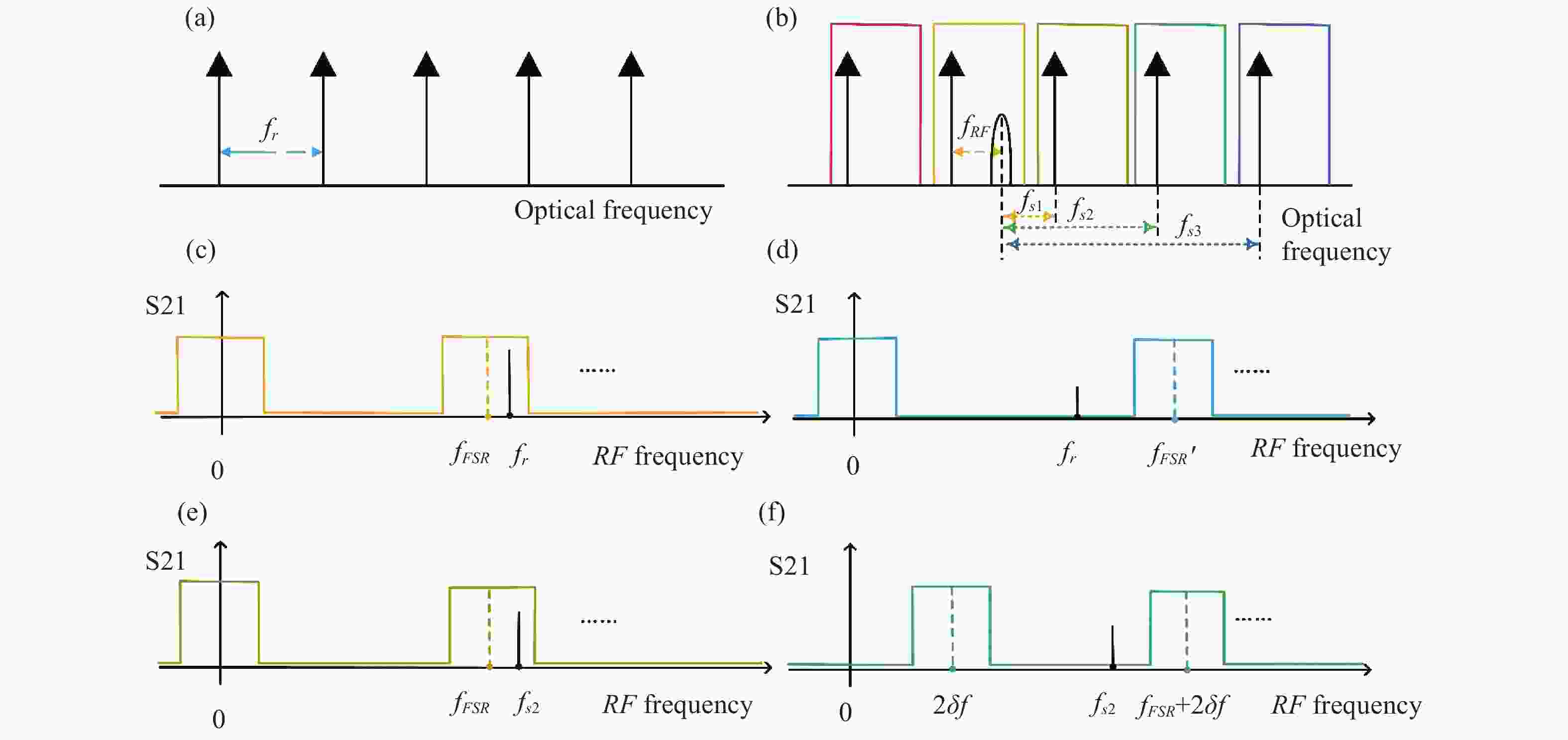
图 2 杂散抑制原理。 (a) 固定杂散kfr来源示意图;(b)镜频杂散fsk来源示意图;(c) 未引入预色散的H(kωr) S21的响应;(d) 固定杂散H(kωr) S21的响应;(e) 未引入预色散的H(ωs2) S21的响应;(f) 镜频杂散H(ωs2) S21的响应
Figure 2. The principle of spurious suppression. (a) Schematic diagram of the source of kfr; (b) Schematic diagram of the source of fsk ; (c) S21 response of the H(kωr) without pre-dispersion; (d) The S21 response of H(kωr); (e) S21 response of the H(ωsk) without pre-dispersion; (f) The S21 response of H(ωs2)
-
文中提出的高分辨率可重构MPF的仿真setup如图1(a)所示。在仿真中,所有的器件参数及仿真参数都参考实际器件可以实现的典型值设置,并将建模后的器件通过矩阵运算搭建成整体系统。系统产生光频梳的方法为级联调制器法,调制器共包括1个MZM和5个PM。其中,MZM工作在正交偏置点,使用RZ50码型调制以平坦光频梳。该方案产生的光频梳的FSR为11.2 GHz。单边带调制由IQ调制器实现,调制器的上下臂调制器均工作在正交偏置点,上下臂的相位差π/2。色散元件1色散值为405 ps/nm。色散元件2的色散值设置为−1010 ps/nm,由此,可以计算出该MPF的FSR为11.03 GHz。
-
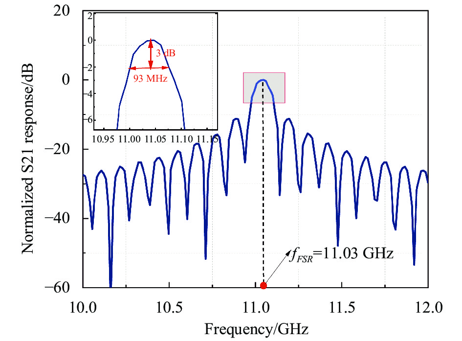
通过光频梳提供的大量抽头,滤波器能够实现很高的频率分辨率。从图3(a)中可以看出,通过级联电调制器法产生的光频梳平坦且对称,共实现了101根平坦梳齿。设置waveshaper为全通,即使用全部梳齿作为抽头时,测量滤波器能够达到的频率分辨率。此时,滤波器的响应如图4所示,测量得到的sinc响应形状滤波器的3 dB带宽可以达到93 MHz,完成了数十MHz的频率分辨率。这表明以光频梳为基础的微波光子滤波器可以使用大数量的梳齿来实现高的频率分辨率。

图 3 光频梳及经waveshaper幅度配置后的光载射频信号光谱图。(a) 光频梳的光谱图;(b) 经过waveshaper输出后抽头系数为正的部分;(c) 经过waveshaper输出后抽头系数为负的部分
Figure 3. The optical spectrum of OFC and the signals after waveshaper amplitude configuration. (a) Optical spectrum of the optical frequency comb; (b) The waveshaper outputs for positive taps; (c) The waveshaper outputs for negative taps

图 4 响应形状为sinc形的滤波器FSR及其3 dB带宽
Figure 4. The FSR and 3 dB bandwidth of a sinc shape filter
-
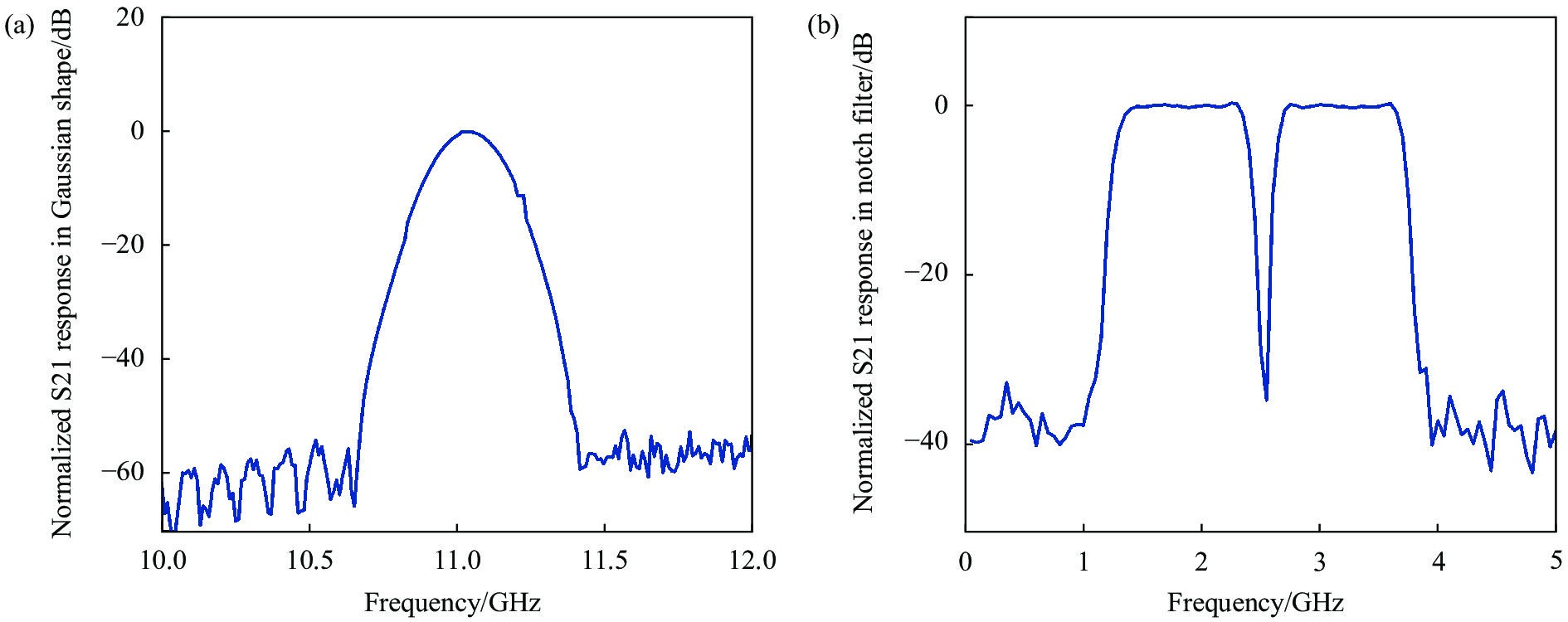
通过对滤波器抽头的设置,滤波器的形状可重构能力也被验证。通过对抽头的不同配置,滤波器形状能够实现滤波中心频率、带宽、形状的任意可重构。图5展示了三种不同的基本滤波器响应S21。图5(a)展示了低通滤波器的响应,其截止频率分别为0.588、1.76、2.94、4.11 GHz。图5(b)展示了截止频率分别为0.588、1.76、2.94、4.11 GHz的高通滤波器。图5(c)展示了中心频率分别为1.76、2.94、4.11 GHz的带通滤波器,其旁瓣抑制约为40 dB。图5(d)展示了中心频率分别为1.76、2.94、4.11 GHz的带阻滤波器。除了基础的滤波形状,图6(a)和(b)分别展示滤波器所产生的高斯形滤波器和陷波滤波器形状。

图 5 归一化S21响应。(a) 低通滤波器;(b) 高通滤波器;(c) 带通滤波器;(d) 带阻滤波器
Figure 5. Normalized S21 response. (a) Lowpass filters; (b) High-pass filters; (c) Bandpass filters; (d) Band-stop filters

图 6 典型形状滤波器的S21响应。(a) 高斯型滤波器的S21响应;(b) 陷波滤波器的S21响应
Figure 6. Normalized S21 responses of typical filter shapes. (a) Normalized S21 response of Gaussian filter; (b) Normalized S21 response of a notch filter
-
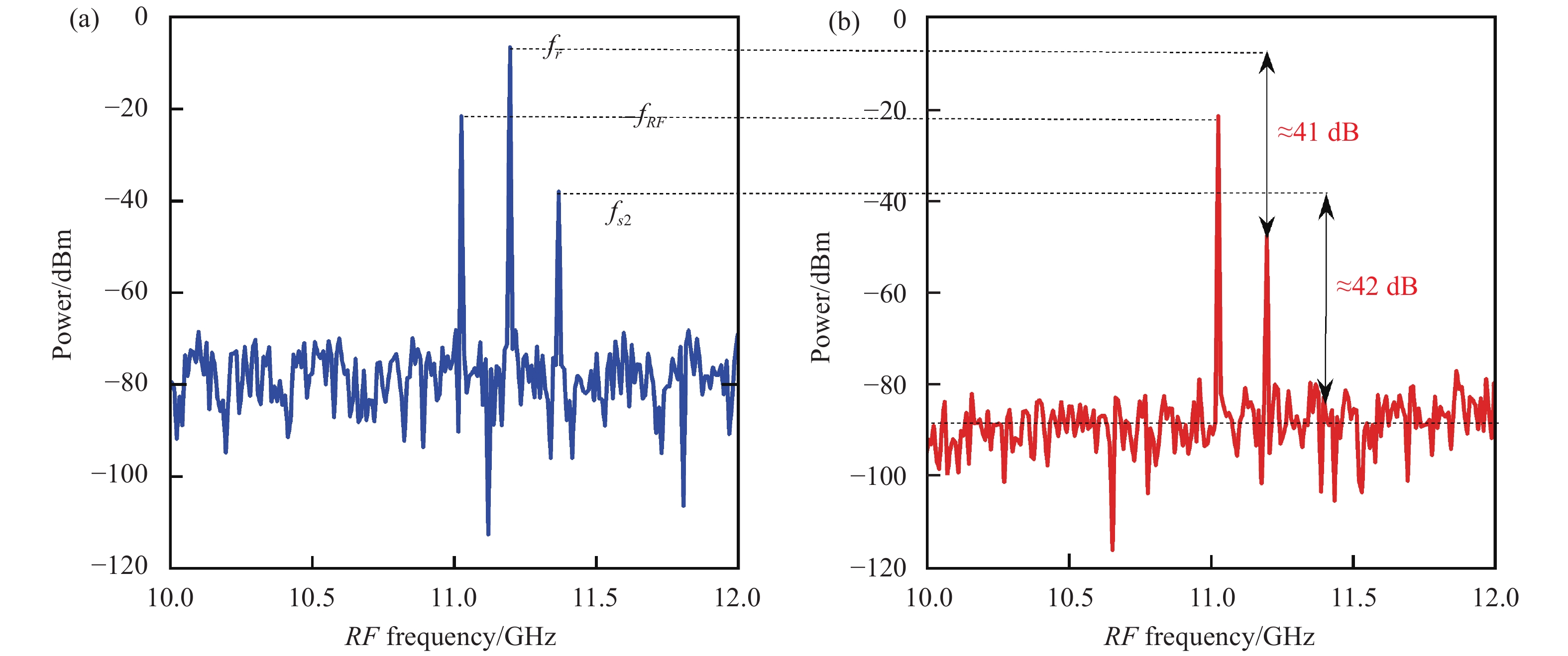
除此之外,通过在调制前引入预色散,可以对杂散进行有效抑制。根据仿真中的参数设置,滤波器的相应的FSR为11.03 GHz。引入预色散后,杂散频率成分kfr的FSR变为18.41 GHz,杂散频率成分fsk的FSR保持不变,但其整体向右平移了8.98 GHz。为了更好观察预色散对系统的杂散抑制效果,将频率为11.03 GHz的单音信号输入系统中,观察系统输出信号的频谱。如图7(a)所示,在不引入预色散的情况下,系统输出存在三个频率:输入的射频频率11.03 GHz,很强的梳齿间拍频fr=11.2 GHz以及梳齿同其它边带之间的拍频fs2=2fr−fRF=11.37 GHz。杂散频率的功率甚至超过了信号功率,严重限制了滤波器的性能。引入预色散后,系统输出见图7(b),可以看出频率为11.2 GHz的杂散被抑制约41 dB,而频率为11.37 GHz的杂散被抑制约42 dB。这表明预色散的引入能够对滤波器中的杂散进行有效抑制,扩大了滤波器的频率工作范围。
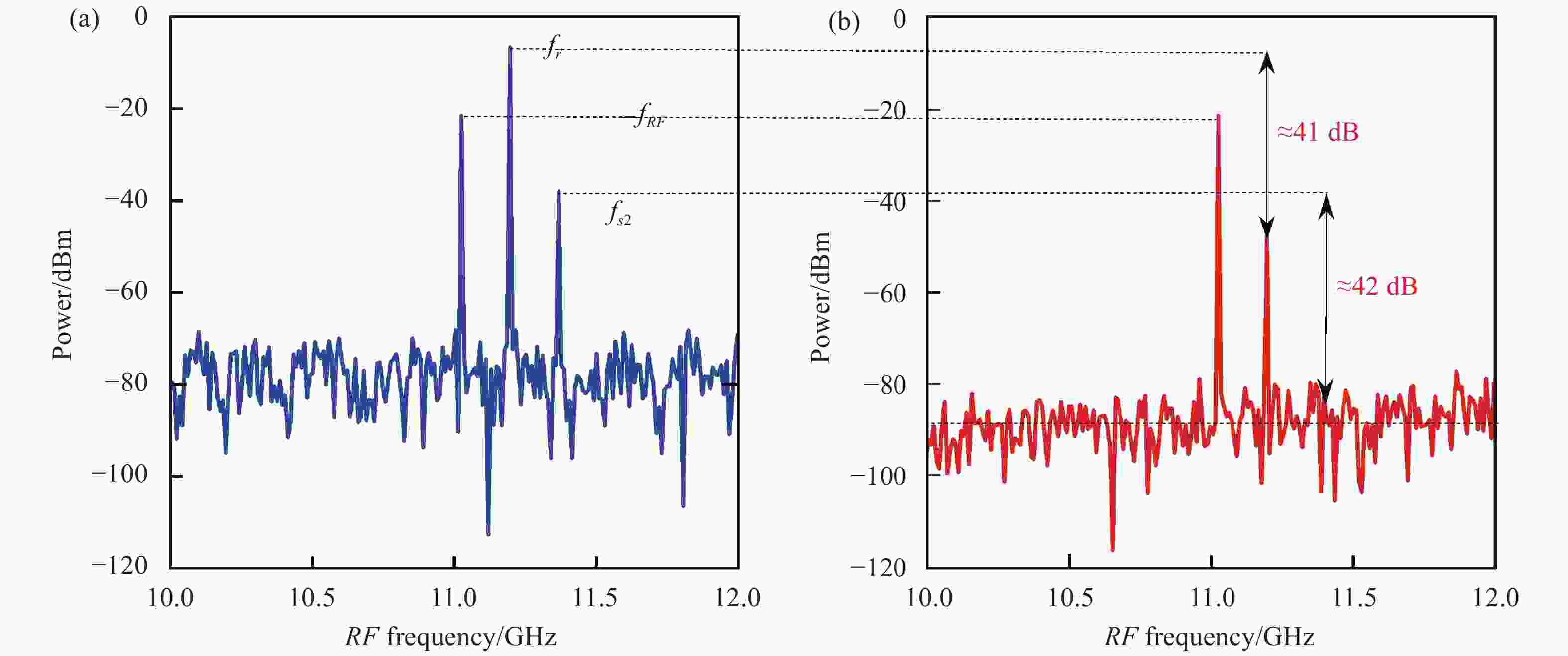
图 7 输入单音信号频率为11.03 GHz时的输出频谱图。(a) 没有预色散的情况;(b) 有色散值405 ps/nm的情况
Figure 7. Spectrum of the output signal, when a single RF signal of 11.03 GHz is directly into the filter. (a) Without the pre-dispersion; (b) With the dispersion of 405 ps/nm
-
文中基于光频梳的微波光子滤波器理论,提出了一种能够实现任意滤波形状的高分辨率可重构MPF方案。通过将级联电光调制器法产生的光频梳作为光源,使用waveshaper对信号的幅度进行灵活配置,并将信号分为两路从两个独立的端口输出。在恢复宽带射频信号时,采用相干探测技术,在物理上实现滤波器的正负抽头,最终完成无低通响应的任意响应形状的重构。大梳齿数量的平坦光频梳提高了抽头数量,实现了滤波器的高分辨率。此外,由于载波和边带引入的色散值不同,该滤波器能够有效抑制杂散频率分量。仿真展示了滤波器具有的93 MHz的高分辨率响应,并且构造了具有不同中心频率的低通、带通、高通和带阻滤波器,以及矩形、高斯形、sinc形等任意滤波形状。此外,通过引入预色散,滤波器的杂散抑制比达到了40 dB以上。相关研究成果对微波光子滤波器性能改善具有重要意义。为了进一步提高滤波器的分辨率,可以通过增加级联相位调制器或加入非线性元件引入非线性效应提高光频梳的梳齿数量,从而提高抽头数量,实现分辨率的提高。此外,由于研究中杂散抑制比与现实需求相比仍相对较低,未来可探寻进一步提高杂散抑制比的新方法。
High resolution microwave photonic filter with arbitrary filtering shape
-
摘要: 提出了一种能够实现任意滤波形状的高分辨率可重构微波光子滤波器方案。利用可编程光滤波器完成抽头系数的独立灵活配置,配合使用相干探测技术实现滤波器的正负抽头,从而可以完成滤波形状的任意可重构。研究表明一个大梳齿数量的平坦光频梳被作为光源可提高抽头数量,从而实现高分辨率的滤波器的重构。除此之外,通过预先引入色散,响应中的杂散也被有效地抑制。经仿真验证,该滤波器具有93 MHz的高分辨率,杂散抑制40 dB以上,创新性地构造了具有不同中心频率的低通、带通、高通、带阻滤波器,以及矩形、高斯形、sinc形等任意滤波形状,对于后续微波光子滤波器的研究起到了引导性作用。Abstract:
Objective Microwave photonic filter is one of hot research topics in recent years due to their ability to achieve high bandwidth, anti-electromagnetic interference, fast tunability and reconfigurability with the advantage of optical devices. In order to realize the flexible reconfiguration of the filter response, the response can be flexibly configured by constructing a finite impulse response filter in the optical domain, where the taps can be flexibly configured. Optical frequency combs are capable of providing a larger number of combs as filter taps and are now widely used. A large number of combs allow for more taps, implying a larger quality factor and a larger time bandwidth product, which also allows for higher frequency resolution. However, in optical frequency comb-based filter schemes, simply having a large number of taps are not enough to achieve arbitrary reconfigurability of the filter shape. It is well known that positive coefficient tapped finite impulse response filters can only achieve a low-pass response, whereas bandpass, high-pass or more complex waveforms require the introduction of negative coefficients in the taps. With the help of programmable waveshaper to differentially control different combs of the optical frequency comb in the optical domain, combined with optical devices such as photodetectors, filters with positive and negative coefficients can be realized. In addition, in the process of realizing the response, the beat frequency between the comb lines of the optical frequency comb introduces unwanted spuriousness. Therefore, the operating frequency of existing optical comb-based microwave photonic filter schemes must be strictly limited to a single "Nyquist zone," which undoubtedly limits the operating frequency range of the filter. By introducing proper pre-dispersion, this spurious signal can be effectively suppressed and the operating frequency range of microwave photonic filter can be expanded. Methods A high-resolution reconfigurable microwave photonic filter scheme based on optical frequency comb is proposed to address the above problem (Fig.1). By using waveshaper to realize the independent and flexible configuration of each tap, combined with balanced photodetectors, the positive and negative taps of the filter are realized, which can complete the formation of arbitrary filter waveforms without low-pass response. By using a flat optical frequency comb with a large number of combs generated by a cascaded electro-optic modulator as a light source, the filter is able to achieve high resolution in the order of tens of MHz. At the same time, the spurious signals are effectively suppressed by introducing pre-dispersion so that different values of dispersion are introduced to the carrier and sidebands (Fig.2). Results and Discussions The simulation verifies that the filter has a high resolution of 93MHz (Fig.3), (Fig.4), the spurious suppression of more than 40 dB (Fig.7), and the innovative construction of low-pass, band-pass, high-pass, and band-stop filters with different center frequencies, as well as arbitrary filter shapes such as rectangular, Gaussian, and sinc (Fig.5), (Fig.6), which plays a leading role in the subsequent research of microwave photonic filter. Conclusions The theory of microwave photonic filter based on optical frequency combs proposes a high-resolution reconfigurable microwave photonic filter scheme capable of realizing arbitrary filter shapes. By using the optical frequency comb generated by the cascaded electro-optic modulator method as a light source, the amplitude of the signal is flexibly configured using a waveshaper, and the signal is split into two outputs from two independent ports. In recovering the broadband radio frequency signal, coherent detection technique is used to physically realize the positive and negative taps of the filter, which ultimately accomplishes the reconstruction of arbitrary response shapes without low-pass response. A flat optical frequency comb with a large number of combs increase the number of taps and realizes the high resolution of the filter. In addition, the filter is able to effectively suppress the spurious frequency components due to the different dispersion values introduced by the carrier and sidebands. Simulations demonstrate the high-resolution response of the filter at 93 MHz, and low-pass, band-pass, high-pass, and band-stop filters with different center frequencies, as well as arbitrary filter shapes such as rectangular, Gaussian, and sinc shapes, are constructed. In addition, by introducing pre-dispersion, the filter achieves a spurious rejection ratio of more than 40 dB. -
图 1 (a) 基于FIR原理的MPF框图;(b) MPF原理图
Figure 1. (a) The diagram of the microwave photonics filter based on FIR principle; (b) Principle of the MPF
图 2 杂散抑制原理。 (a) 固定杂散kfr来源示意图;(b)镜频杂散fsk来源示意图;(c) 未引入预色散的H(kωr) S21的响应;(d) 固定杂散H(kωr) S21的响应;(e) 未引入预色散的H(ωs2) S21的响应;(f) 镜频杂散H(ωs2) S21的响应
Figure 2. The principle of spurious suppression. (a) Schematic diagram of the source of kfr; (b) Schematic diagram of the source of fsk ; (c) S21 response of the H(kωr) without pre-dispersion; (d) The S21 response of H(kωr); (e) S21 response of the H(ωsk) without pre-dispersion; (f) The S21 response of H(ωs2)
图 3 光频梳及经waveshaper幅度配置后的光载射频信号光谱图。(a) 光频梳的光谱图;(b) 经过waveshaper输出后抽头系数为正的部分;(c) 经过waveshaper输出后抽头系数为负的部分
Figure 3. The optical spectrum of OFC and the signals after waveshaper amplitude configuration. (a) Optical spectrum of the optical frequency comb; (b) The waveshaper outputs for positive taps; (c) The waveshaper outputs for negative taps
图 4 响应形状为sinc形的滤波器FSR及其3 dB带宽
Figure 4. The FSR and 3 dB bandwidth of a sinc shape filter
图 5 归一化S21响应。(a) 低通滤波器;(b) 高通滤波器;(c) 带通滤波器;(d) 带阻滤波器
Figure 5. Normalized S21 response. (a) Lowpass filters; (b) High-pass filters; (c) Bandpass filters; (d) Band-stop filters
图 6 典型形状滤波器的S21响应。(a) 高斯型滤波器的S21响应;(b) 陷波滤波器的S21响应
Figure 6. Normalized S21 responses of typical filter shapes. (a) Normalized S21 response of Gaussian filter; (b) Normalized S21 response of a notch filter
-
[1] Capmany J, Ortega B, Pastor D, et al. A tutorial on microwave photonic filters [J]. Journal of Lightwave Technology, 2006, 24(1): 201-229. doi: 10.1109/JLT.2005.860478 [2] Minasian R A, Chan E H W, Yi X K, et al. Photonic signal processing of microwave signals [J]. IEEE Transactions on Microwave Theory and Techniques, 2006, 54(2): 832-846. doi: 10.1109/TMTT.2005.863060 [3] Yao J. Microwave photonics [J]. Journal of Lightwave Technology, 2009, 27(3): 314-335. doi: 10.1109/JLT.2008.2009551 [4] 邢云路, 李尚远, 薛晓晓, 等. 高频宽带分布相参微波光子成像雷达研究[J]. 中国激光, 2021, 48(15): 422-435. Xing Yunlu, Li Shangyuan, Xue Xiaoxiao, et al. High-frequency broadband-distributed coherent-aperture microwave photonic imaging radar [J]. Chinese Journal of Lasers, 2021, 48(15): 1517003. (in Chinese) [5] 李明, 郝腾飞, 李伟. 微波光子与多学科交叉融合的前景展望(特邀)[J]. 红外与激光工程, 2021, 50(07): 8-11. doi: 10.3788/IRLA20211042 Li Ming, Hao Tengfei, Li Wei. High-frequency broadband-distributed coherent-aperture microwave photonic imaging radar [J]. Infrared and Laser Engineering, 2021, 50(7): 20211042. (in Chinese) doi: 10.3788/IRLA20211042 [6] Shu H, Chang L, Tao Y, et al. Microcomb-driven silicon photonic systems [J]. Nature, 2022, 605(7910): 457-463. doi: 10.1038/s41586-022-04579-3 [7] Li J, Dai Y, Yin F, et al. Megahertz-resolution programmable microwave shaper [J]. Optics Letters, 2018, 43(8): 1878-1881. doi: 10.1364/OL.43.001878 [8] Gao Y, Li S, Xue X, et al. W-band high-Q microwave photonic filter with the third-order dispersion precompensation [J]. Journal of Lightwave Technology, 2018, 36(11): 2152-2160. doi: 10.1109/JLT.2018.2806182 [9] Chen H, Lee M, Won Y H, et al. High-speed switchable dual-passband microwave photonic filter with dual-beam injection in an SMFP-LD [J]. Journal of Lightwave Technology, 2021, 39(24): 7966-7972. doi: 10.1109/JLT.2021.3080826 [10] Wang T, Xiao J L, Wu J L, et al. Dual-passband microwave photonic filter based on a directly modulated microcavity laser [J]. IEEE Photonics Technology Letters, 2021, 33(4): 185-188. doi: 10.1109/LPT.2021.3050818 [11] Capmany J, Pastor D, Ortega B, et al. New and flexible fiber-optic delay-line filters using chirped Bragg grattings and laser arrays [J]. IEEE Transactions on Microwave Theory and Techniques, 1999, 47(7): 1321-1326. doi: 10.1109/22.775473 [12] Jiao Z, Yao J. Passband-switchable and frequency-tunable dual-passband microwave photonic filter [J]. Journal of Lightwave Technology, 2020, 38(19): 5333-5338. doi: 10.1109/JLT.2020.2991364 [13] Hamidi E, Leaird D E, Weiner A M, et al. Tunable programmable microwave photonic filters based on an optical frequency comb [J]. IEEE Transactions on Microwave Theory and Technique, 2010, 58(11): 3269-3278. doi: 10.1109/TMTT.2010.2076970 [14] 薛晓晓, 郑小平. 基于集成光频梳的新型微波光子应用(特邀)[J]. 红外与激光工程, 2021, 50(7): 24-28. doi: 10.3788/IRLA20211046 Xue Xiaoxiao, Zheng Xiaoping. Novel microwave photonic applications based on integrated microcombs (Invited) [J]. Infrared and Laser Engineering, 2021, 50(7): 20211046. (in Chinese) doi: 10.3788/IRLA20211046 [15] 张馨, 张江华, 李仪茗, 等. 高平坦大带宽可调谐电光光频梳光源[J]. 中国激光, 2021, 48(1): 0116002. doi: 10.3321/j.issn.0258-7025.2021.1.zgjg202101024 [16] Song M, Long C M, Wu R, et al. Reconfigurable and tunable flat-top microwave photonic filters utilizing optical frequency combs [J]. IEEE Photonics Technology Letters, 2011, 23(21): 1618-1620. doi: 10.1109/LPT.2011.2165209 [17] Zhu Z, Chi H, Jin T, et al. All-positive-coefficient microwave photonic filter with rectangular response [J]. Optics Letters, 2017, 42(15): 3012-3015. doi: 10.1364/OL.42.003012 [18] Tan M, Xu X, Wu J, et al. Photonic RF and microwave filters based on 49 GHz and 200 GHz Kerr microcombs [J]. Optics Communications, 2020, 465: 125563. doi: 10.1016/j.optcom.2020.125563 [19] Xue X, Xuan Y, Kim H, et al. Programmable single-bandpass photonic RF filter based on Kerr comb from a microring [J]. Journal of Lightwave Technology, 2014, 32(20): 3557-3565. doi: 10.1109/JLT.2014.2312359 [20] 贺超, 廖同庆, 吴昇等. 可调谐窄带宽的负系数微波光子滤波器[J]. 红外与激光工程, 2017, 46(09): 137-142. doi: 10.3788/IRLA201746.0920003 He Chao, Liao Tongqing, Wu Sheng, et al. Tunable narrow bandwidth negative coefficient microwave photonic filter [J]. Infrared and Laser Engineering, 2017, 46(9): 0920003. (in Chinese) doi: 10.3788/IRLA201746.0920003 [21] 严艺, 廖同庆, 吕晓光等. 新型多抽头复系数微波光子滤波器[J]. 红外与激光工程, 2019, 48(1): 237-242. doi: 10.3788/IRLA201948.0120001 Yan Yi, Liao Tongqing, Lv Xiaoguang, et al. Novel multitap complex coefficient microwave photonic filter [J]. Infrared and Laser Engineering, 2019, 48(1): 0120001. (in Chinese) doi: 10.3788/IRLA201948.0120001 [22] Liao J, Xue X, Wen H, et al. A spurious frequencies suppression method for optical frequency comb based microwave photonic filter [J]. Laser & Photonics Reviews, 2013, 7(4): L34-L38. -

 点击查看大图

计量
- 文章访问数: 190
- HTML全文浏览量: 57
- PDF下载量: 66
- 被引次数: 0

