


 下载:
下载:


-
以地球临边或深空为背景进行目标探测是运行于地球邻近轨道空间光学遥感器的一种重要成像方式[1],可以有效减少或规避地球辐射影响,广泛适用于弱背景、弱目标探测领域,如弹道导弹中段预警[2]、空间目标监视[3]、临边大气背景特性测量[4-5]、天文探测[6]等。对于地球临边或深空背景探测系统,遥感器在轨运行时虽然将地球控制在系统光学视场外,但视场外杂光仍会通过非成像光路到达像面,对遥感器成像产生影响。如NASA研究银河系进化的WIRE除设计了传统的遮光罩外,还在遮光罩前段增加了“Aperture Shade”以遮挡来自地球等视场外杂散辐射,将其控制在总背景辐射10%以下[7]。地球辐射产生的杂散光在遥感器总杂散光中的占比,对遥感器探测灵敏度的影响,是遥感器指标论证分析的关键环节,其抑制设计需在遥感器研制过程中迭代优化。
地球辐射包括透过大气的地物能量、大气自发辐射能量、大气对太阳辐射的后向散射能量,其中透过大气的地物能量又包括地物热辐射、地物反射的大气辐射、地物反射的太阳漫射辐射,地物反射的太阳直射辐射等四种;地球辐射与地物类型、大气条件、观测几何、太阳几何等均有关[8],因其复杂性,目前杂光分析软件尚无法直接精确分析地球杂光的影响;文献[9-10]对于基于地球漫射模型,建立了地表反照光及地球热辐射杂光模型,但对于以临边及深空为背景的甚高灵敏度探测系统,仅考虑这两种辐射的地球杂光模型还存在不足。
文中对地球杂散辐射影响进行了建模分析,模型包括地表球冠杂散辐射模型、球冠任意点经纬度计算模型、球冠任意点太阳矢量模型。并以某空间光学遥感器可见光及长波红外谱段为例,从星下点位置、时间、载荷视轴指向等各维度进行了地球杂散辐射仿真,对仿真结果进行了归纳总结。研究成果可广泛应用于以地球临边或深空为背景的遥感系统总体设计工作。
-
如图1所示,$ O{\text{-}}XYZ $表示地球固定坐标系,$ X $轴指向0°经线与赤道的交点,$ Y $轴指向90°E经线与赤道的交点,$ Z $轴满足右手螺旋关系;$ T {\text{-}} {X_T}{Y_T}{Z_T} $为$ T $点的本地坐标系,$ {Z_T} $轴指向地心,$ {X_T} $轴指向正北,$ {Y_T} $轴满足右手螺旋关系;$ A {\text{-}} {X_A}{Y_A}{Z_A} $为卫星$ A $的本体坐标系,$ {Z_A} $轴指向地心,$ {X_A} $轴指向卫星飞行方向,$ {Y_A} $轴满足右手螺旋关系。$ S $为卫星星下点,$ {T_O} $为$ T $在线段$ AO $上的垂足,$ P $、$ Q $为卫星$ A $与地表的切点,${S _u}$、${S _d}$为圆$ {T_O} $与弧$\widehat{P Q} $的交点。显然,球冠$O{\text{-}}PS Q$上任意$ T $点的辐射能量均会到达卫星,不同地面点产生的杂散辐射是多方向平行光组成的各向异性入射辐射能量。

图 1 地球杂散辐射计算原理图
Figure 1. Schematic diagram of calculation of earth stray radiation
由图1可知,任意点$ T $在球冠地表上截取一个圆环状小面元的面积可表示为:
$$ {\rm{d}}s=R{\rm{d}}\alpha \cdot R\mathrm{sin}\alpha {\rm{d}}\beta $$ (1) 式中:$ R $为地球半径;$\; \beta $为方位角,取值范围为$ \left[ {0,2\pi } \right] $;$ \alpha $为地心角,取值范围$\left[ {0,\arccos \left(\dfrac{R}{{R + h}}\right)} \right]$;$ h $为轨道高度;则卫星接收$ T $处环状小面元的辐射通量可表示为:
$$ {\rm{d}}\varphi =\frac{L{\rm{d}}s\cdot \mathrm{cos}\rho {\rm{d}}{A}_{r}}{{\left|{{TA}}\right|}^{2}} $$ (2) 式中:$\; \rho $为$ T $处环状小面元法线矢量${{n}}$与矢量${{TA}}$的夹角,$\; \rho = \alpha + \varepsilon $,$ \varepsilon $为矢量${{AT}}$与$ Z_{A} $轴的夹角;$ {A_r} $表示卫星在矢量${{TA}}$方向上的投影面积;卫星到$ T $点的距离为矢量${{TA}}$的长度,记为$\left| {{{TA}}} \right|$,$\left| {{{TA}}} \right| = (R + h)\cos \varepsilon - \sqrt {{R^2} - {{(R + h)}^2}{{\sin }^2}\varepsilon }$[11];$ L $为$ T $处环状小面元的在大气层顶的辐射亮度。进一步得到$ T $处环状小面元在矢量${{TA}}$方向上辐射照度为${\rm{d}}{E_o} = {\rm{d}}\varphi /{\rm{d}}{A_r}$,整理可得:
$$ {\rm{d}}{E}_{o}=\frac{L{R}^{2}\mathrm{sin}\alpha \cdot \mathrm{cos}\left(\alpha +\varepsilon \right){\rm{d}}\alpha {\rm{d}}\beta }{{\left[(R+h)\mathrm{cos}\varepsilon -\sqrt{{R}^{2}-{(R+h)}^{2}{\mathrm{sin}}^{2}\varepsilon }\right]}^{2}} $$ (3) 可采用点源透射比(Point source transmission, PST)函数来计算相机光学系统视场外点源目标在像面的辐射能量[12-13],由点源透射比定义可得$ T $处环状小面元在像面的照度${\rm{d}}{E_i}$为:
$$ {\rm{d}}{E_i} = pst\left( {\eta ,\xi } \right){\rm{d}}{E_o} $$ (4) 式中:$ pst\left( {\eta ,\xi } \right) $为相机点源透过比函数;$ \eta $表示$ T $处环状小面元辐射平行光与相机光轴的夹角,即光轴矢量与矢量${{AT}}$的夹角;$ \xi $为与以某一参考方向为基准的入射方位角。对于圆对称光学系统,相同$ \eta $角,不同方位角$ \xi $,点源透过率基本是一致的,可以忽略方向角的影响,进而得到$ T $处环状小面元到达像面的照度为:
$$ {\rm{d}}{E_i} = \frac{{pst\left( \eta \right)L{R^2}\sin \alpha \cos \left( {\alpha + \varepsilon } \right){\rm{d}}\alpha {\rm{d}}\beta }}{{{{\left[ {(R + h)\cos \varepsilon - \sqrt {{R^2} - {{(R + h)}^2}{{\sin }^2}\varepsilon } } \right]}^2}}} $$ (5) 公式(5)积分可得球冠地表$O{\text{-}}PS Q$到达相机像面处的总辐射照度$ {E_i} $为:
$$ {E_i} = \int_0^{2\pi } {\int_0^{\arccos \left(\tfrac{{R} }{{{R} + h}}\right)} {{\rm{d}}{E_i}} } $$ (6) 实际上,任意点$ T $处环状小面元的在大气层顶的辐射亮度$ L $包含了地球自身辐射、路径散射、反射太阳等,取值与地物类型、大气条件、观测几何、太阳几何等均有关,可由大气仿真模型Modtran、6S仿真求解。卫星对任意点$ T $的观测几何、太阳几何需要根据其经纬度及星下点$ S $经纬度、太阳几何求解,其中涉及$ T $点的经纬度可由星下点的$ S $的经纬度及卫星轨道参数计算,具体流程如图2所示。卫星对任意点$ T $的观测几何可根据求解的$ T $点经纬度坐标变换获得,文中不再赘述,文中主要研究内容集中在图2紫色框图标注的模型,下面展开介绍球冠任意点经纬度模型及太阳矢量模型。

图 2 地球杂散辐射计算流程
Figure 2. Calculation flow of the earth stray radiation
-
根据卫星轨道参数,由轨道动力学可计算任意时刻星下点$ S $点所在的经纬度,记为$ {L_S} $、$ {B_S} $,据此可求得球冠地表$O{\text{-}}PS Q$上任意点$ T $对应的经纬度。首先,求$ T $点的所在的纬度$ {B_T} $如图3所示,图中相同符号含义与图1相同,圆$ {O_S} $为星下点$ S $所在的纬度圆环,$ {O_T} $为任意点$ T $所在的纬度圆环,与弧$\widehat{P Q}$交于点$ {T_B} $;圆$ {O_S} $、$ {O_T} $与圆$ {T_O} $的平面夹角为$ \gamma $,$ \gamma = {90^ \circ } - {B_S} $;$ {T_B}{S_T} $平行于$ OS $,交圆$ {T_O} $于$ {S_T} $;$ H $为$ T $在线段$ {T_O}{S_T} $上的垂足。由图3几何关系有:圆$ {T_O} $半径$ r = R\sin (\alpha ) $,弦高$d = R - \sqrt {{R^2} - {r^2}}$,线段$ {T_O}H = r\cos (\beta ) $,$ {T_O}F = {T_O}H\tan (\gamma ) $, $OF = R - d - {T_O}F$;则纬度可由下式计算:
$$ \begin{split} {B_T} =& {\rm{arccos}} \left(\frac{{O{O_T}}}{R}\right) = {\rm{arccos}} \left(\frac{{OF\cos (\gamma )}}{R}\right) = \\& {\rm{arccos}} \left[ {\cos (\alpha )\cos (\gamma ) - \sin (\alpha )\sin (\gamma )\cos (\beta )} \right] \end{split}$$ (7) 
图 3 纬度求解示意图
Figure 3. Schematic diagram of latitude calculation
然后,求$ T $点的所在的经度$ {L_T} $,图4给出了星下点在北半球时的经度求解几何模型,图中相同符号含义与图1、图3相同。线段$ {S_d}{S_u} $与地球固定坐标系$O{\text{-}}XY Z$中$ Z $轴交点为$ Q $。由图3几何关系有,$HT = r\sin (\beta )$,$ {T_B}{O_T} = R\cos ({B_T}) $,$ Q{T_O} = \left( {R - d} \right)\tan (\gamma ) $。当$ r \leqslant \left| {Q{T_O}} \right| $时,圆$ Q $与圆${{{T}}_{{O}}}$无交点或一个交点;当$r \gt \left| {Q{T_O}} \right|$时圆$ Q $与圆 ${{{T}}_{{O}}}$交点为$ M $、$ N $,进而可得弧度${ \widehat{N S_d} }= { 180}^{\circ }-{\rm{arccos}}\left(\left|Q{T}_{O}\right|/r\right)$,${\widehat{M S_d}} ={180}^{\circ }+{\rm{arccos}}\left(\left|Q{T}_{O}\right|/r\right)$。已知$ S $点经度为$ {L_S} $,则$ T $点的经度为$ {L}_{T}={L}_{S}+\widehat{{T}_{B}T} $,弧度$ {\widehat{{T}_{B}T}} $需根据$ r $及$\; \beta $的取值范围分情况讨论,总结计算公式如下:
$$ {L}_{T}=\left\{\begin{array}{l}{L}_{s}+{180}^{\circ }-\mathrm{arcsin}\left(HT/{T}_{B}{O}_{T}\right),r \gt \left|Q{T}_{O}\right| \&\\\quad \widehat{N S_d}< \beta < \widehat{M S_d} \\ {L}_{s}+\mathrm{arcsin}\left(HT/{T}_{B}{O}_{T}\right){,}\;{\rm{else}}\end{array}\right. $$ (8) 
图 4 经度求解几何模型
Figure 4. Solving geometric models with longitude
同理,当星下点位于南半球时,$ r \gt \left| {Q{T_O}} \right| $时,$\widehat{N S_d}= {\rm{arccos}} \left(\left|Q{T}_{ O}\right|/r\right)$, $\widehat{M S_{ d}} = {360}^{\circ } - {\widehat{M S_{ d}}} = {360}^{\circ } - {\rm{arccos}}\left( {\left| {Q{T_{ O}}} \right|/r} \right)$,进而得到:
$$ {L}_{T}=\left\{\begin{array}{l}{L}_{s}+\mathrm{arcsin}\left(HT/{T}_{B}{O}_{T}\right),\;{\widehat{N S_{ d}}} \lt \beta \lt {\widehat{M S_{ d}}}\\ {L}_{s}+{180}^{\circ }-\mathrm{arcsin}\left(HT/{T}_{B}{O}_{T}\right)\text{, }\;{\rm else}\end{array}\right. $$ (9) 图5以运行于800 km轨道高度卫星为例,根据模型仿真分析给出了不同卫星位置(以星下点经纬度表示)时,地球辐射能量能够到达卫星的地表冠状区域在二维世界地图上的投影显示。
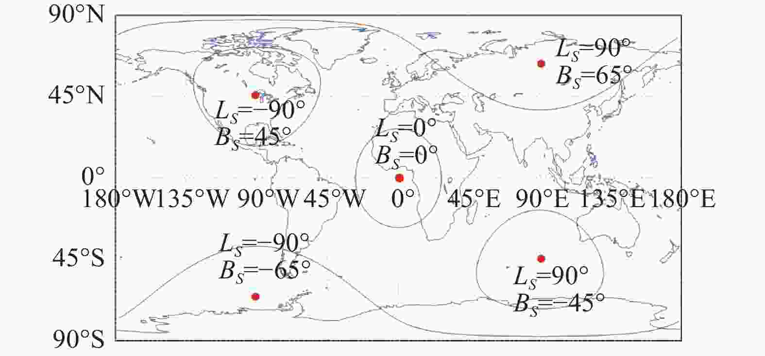
图 5 不同卫星位置时地表辐射能够到达卫星的区域
Figure 5. The area where the surface radiation can reach the satellite at different satellite positions
-
根据星下点经纬度及地方时,由经典太阳位置算法[14]可计算星下点$ S $本地坐标系下当地地方时刻$ t $的太阳矢量(指向太阳)为${{{V}}_S}\left( t \right) = {\left[ {{V_{Sx}}\left( t \right),{V_{Sy}}\left( t \right),{V_{Sy}}\left( t \right)} \right]^{\rm{T}}}$。根据$ S $点及任意地点$ T $的经纬度,可得到地球固定坐标系$O{\text{-}}XY Z$到$ S $、$ T $点本地坐标系的转换矩阵为:
$$ \begin{split} & {R_{O - S}}{{ = }}{R_y}( - {B_s}){R_x}({L_s}){R_y}( - {90^{{\circ }}}) \\& {R_{O - T}}{{ = }}{R_y}( - {B_T}){R_x}({L_T}){R_y}( - {90{{^\circ }}}) \end{split} $$ (10) 式中:$ {R_x}\left( \cdot \right) $、${R_y}\left( \cdot \right)$分别表示绕$ X $、$ Y $轴的坐标旋转矩阵。因此,星下点$ S $的本地坐标系下的太阳矢量${{{V}}_S}\left( t \right)$在任意地面点$ T $的本地坐标系下的太阳矢量${{{V}}_T}\left( t \right) = {\left[ {{V_{Tx}}\left( t \right),{V_{Ty}}\left( t \right),{V_{T{\textit{z}}}}\left( t \right)} \right]^{\rm{T}}}$可用下式计算:
$$ {{{V}}_{{T}}}\left( t \right) = {R_{O - T}}{R_{O - S}}^{\rm{T}}{\left[ {{V_{Sx}}\left( t \right),{V_{Sy}}\left( t \right),{V_{S{\textit{z}}}}\left( t \right)} \right]^{\rm{T}}} $$ (11) 则任意地面点$ T $的太阳天顶角为:
$$ {\theta _T}\left( t \right) = {\rm{arc}} \cos \left( - \frac{{{V_{T{\textit{z}}}}\left( t \right)}}{{\left| {{{{V}}_T}\left( t \right)} \right|}}\right) $$ (12) 图6以运行于800 km轨道高度卫星为例,根据模型仿真分析给出了卫星下点为$ {L_S} = {0^ \circ } $,$ {B_S} = {0^ \circ } $。不同当地地方时刻,地球辐射能量能够到达卫星的地表冠状区域及其太阳天顶角在世界投影二维地图上的显示。太阳天顶角大于90°,进入夜间,大气层顶辐射能量与太阳无关,因此图6中太阳天顶角大于90°的区域均用黑色表示。

图 6 地表冠状区域及其不同时间的太阳天顶角。(a) 09-23 9:00;(b) 09-23 12:00; (c) 9-23 15:00;(d) 12-22 9:00; (e) 12-22 12:00;(f) 12-22 15:00
Figure 6. Earth spherical crown region and its solar zenith angle at different times. (a) 09-23 9:00; (b) 09-23 12:00;(c) 9-23 15:00; (d) 12-22 9:00; (e) 12-22 12:00; (f) 12-22 15:00
-
下面以某星载遥感器为例进行地球杂散辐射定量分析,卫星平台运行于倾角60°,高度800 km的圆轨道,遥感器通过二维转台方位俯仰运动使遥感器视轴指向地球临边或深空,实现对目标的探测跟踪。遥感器视轴方位角$A{\textit{z}}$与俯仰角$ El $的参考坐标系为图1中的卫星本体坐标系$ A{\text{-}} {X_A}{Y_A}{Z_A} $,角度正负定义按照右手定则。图7给出了通过杂光分析软件仿真获取的该遥感器可见光及长波红外谱段的点源透射比函数。

图 7 点源透射比曲线
Figure 7. Curve of point source transmission
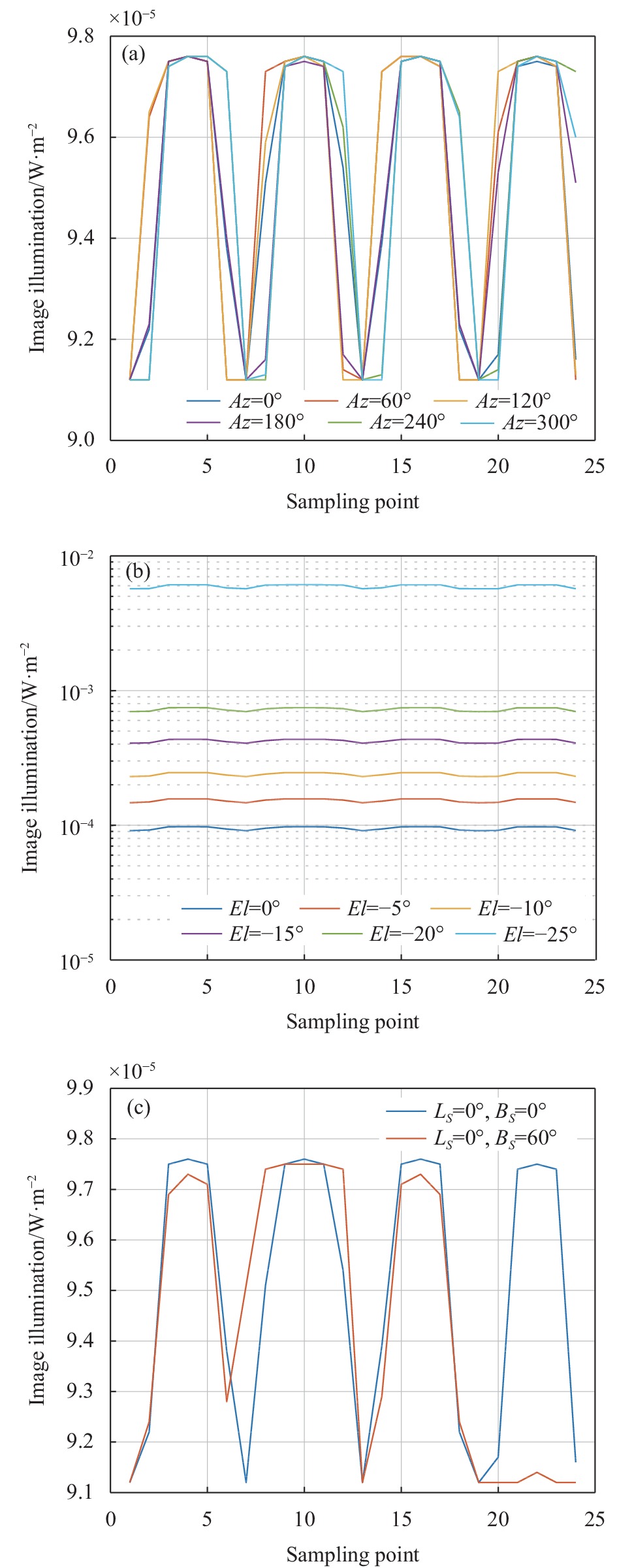
基于图7中的PST数据及文中建立的地球杂散辐射模型,分别分析了地球杂散辐射对可见光及长波红外谱段的影响分别如图8、图9所示。图中每条曲线共24个时间采样点,顺序对应春分、夏至、秋分、冬至这4个特定日期的6点、9点、12点、15点、18点、24点6个时刻。

图 8 可见光谱段地球杂散辐射分析。(a)不同方位角杂散辐射曲线;(b)不同俯仰角杂散辐射曲线;(c)不同星下点位置杂散辐射曲线
Figure 8. Earth stray radiation analysis in the visible light band. (a) Stray radiation curve at different azimuth angles; (b) Stray radiation curve at different elevation angles; (c) Stray radiation curve at different nadir positions

图 9 长波红外谱段地球杂散辐射分析。(a)不同方位角杂散辐射曲线;(b)不同俯仰角杂散辐射曲线;(c)不同星下点位置杂散辐射曲线
Figure 9. Earth stray radiation analysis in the long wave infrared band. (a) Stray radiation curve at different azimuth angles; (b) Stray radiation curve at different elevation angles; (c) Stray radiation curve at different nadir positions
图8(a)、图9(a)给出了星下点$ {L_S} = {0^ \circ } $,$ {B_S} = {0^ \circ } $,遥感器视轴俯仰角$ El = {0^ \circ } $时,不同方位角$A{\textit{z}}$像面照度随时间的变化曲线。图8(b)、图9(b)给出了星下点$ {L_S} = {0^ \circ } $,$ {B_S} = {0^ \circ } $,遥感器视轴方位角$A{\textit{z}} = {0^ \circ }$时,不同俯仰角$ El $像面照度随时间的变化曲线。图8(c)、图9(c)给出了$A{\textit{z}} = {0^ \circ }$,$ El = {0^ \circ } $时,不同星下点位置时像面照度随时间的变化曲线。
由图中数据分析可得以下结论:
1)地球杂散辐射随时间,即太阳照射情况呈周期性变化,相同星下点及遥感器视轴角度时,不同时间可见光谱段地球杂散辐射有近10倍的波动,长波红外谱段波动较小可忽略。这是符合逻辑的,虽然白天夜间可见光谱段地物辐射亮度有几个量级的差距,但由于地表冠状区域不同地面点产生杂散辐射的平均效应,导致星下点不同时间时差距没有那么明显;此外,长波红外主要为地球自身辐射,受太阳照射影响小,因此随时间变化不明显。
2)地球杂散辐射随视轴俯仰角变化敏感,相同星下点及遥感器视轴方位角,俯仰角变化25°,地球杂散辐射可见光谱段有7个量级的波动,长波红外谱段有两个量级波动。
3)视轴方位角对可见光谱段地球杂散辐射有一定影响,相同星下点及遥感器视轴俯仰角时,不同方位角有近5倍的波动,长波红外谱段可忽略。
4)地理纬度对可见光谱段地球杂散辐射有一定影响,纬度越低,杂散辐射影响越大,对长波红外谱段影响可忽略。因为,可见光谱段受太阳照射条件影响大,纬度越低,光照越强。
-
针对地球临边、深空背景探测类空间光学遥感器地球杂散辐射无法准确模拟问题,文中建立了地表球冠杂散辐射计算模型,并以某空间遥感器可见光及长波红外谱段为例,从星下点位置、时间、载荷视轴指向等各维度进行了地球杂散辐射仿真分析。研究成果可广泛应用于以地球临边、深空为背景的遥感系统总体设计工作。
Modeling and analysis of earth stray radiation of earthlimb/deep space background detection system
-
摘要: 为评估地球杂散辐射对地球临边、深空背景探测类空间光学遥感器成像的影响,指导遥感器杂光抑制设计,对地球杂散辐射进行了建模分析。基于辐射学理论,建立了地表球冠杂散辐射模型,给出了卫星任意位置时对其光学载荷杂光有贡献的地表球冠区域,并采用区域网格化,小面元积分的方法求解地球总的杂散辐射。小面元的辐射能量包括透过大气的地物能量、大气自发辐射能量、大气对太阳辐射的后向散射能量,为准确表征,根据卫星参数建立了小面元的经纬度模型、太阳矢量模型来计算其太阳照射几何,结合卫星观测几何、地表参数、大气参数等,通过大气辐射传输模型仿真求得。以某空间遥感器可见光及长波红外谱段为例,从星下点位置、时间、载荷视轴指向等各维度进行了地球杂散辐射仿真分析。Abstract:
Objective Target detection with earthlimb and deep space background is an important imaging method for spaceborne optical remote sensors, which can effectively reduce the impact of earth stray radiation. It is widely used in weak target detection, such as mid-course warning of ballistic missile, space target monitoring, and astronomical detection. Usually, the earth is controlled outside the field of view of sensors, but the earth stray light will still reach the focal plane through the non-imaging optical path, which will affect the detection of targets. The earth radiation received by a remote sensor includes earth surface energy through the atmosphere, atmospheric spontaneous radiation energy and atmospheric backscattering energy of solar radiation. The earth radiation is related to the types of ground objects, atmospheric conditions, observational geometry, and the geometry of the sun. Due to its complexity, the stray light analysis software has not been able to accurately analyze the influence of earth stray light. In order to evaluate the influence of the earth stray radiation and guide the stray light suppression design of remote sensors, the earth stray radiation is modeled and analyzed. Methods Based on the radiation theory, the radiation model of earth spherical crown is established, and the spherical cap region that contributes to its optical payload stray light at any satellite position is given. The total stray radiation of earth is solved using the method of region meshing and small facet integration (Fig.1). The radiation energy of a small facet includes surface energy passing through the atmosphere, atmospheric spontaneous radiation energy, and atmospheric backscattered energy of solar radiation. For accurate characterization, a latitude longitude model and a solar vector model of small facets are established based on satellite parameters to calculate their solar irradiation geometry (Fig.3-4). Combined with the satellite observation geometry, surface parameters and atmospheric parameters, etc., the radiance is obtained using the atmospheric radiation transfer model. Results and Discussions Taking the visible and long wave infrared band of a spaceborne remote sensor as an example, the comparative analysis of the earth stray radiation is carried out in terms of the nadir location, time and sensor boresight direction (Fig.8-9).The earth stray radiation changes periodically with time. The fluctuation in the visible light band is nearly 10 times at different times and in the long wave infrared band can be ignored. The earth stray radiation is sensitive to the change of boresight elevation angle. There are seven orders of magnitude fluctuations in the visible light band and two orders of magnitude fluctuations in the long wave infrared band when the elevation angle changes 25°. The boresight azimuth angle has an influence on the earth stray radiation in the visible light band and can be ignored in the long wave infrared band. It has nearly five times of fluctuations varying with different azimuth angles. The geographical latitude has an influence on the earth stray radiation in the visible light band and can be ignored in the long wave infrared band. The lower the latitude is, the greater the influence of stray radiation is. Conclusions In order to solve the problem that the earth stray radiation can not be accurately simulated for the spaceborne optical remote sensor used for earthlimb and deep space background target detection, the mathematical model of earth spherical crown stray radiation is established. The visible and long wave infrared band of a spaceborne remote sensor is taken as an example to simulate the earth stray radiation from various dimensions such as the position of the satellite nadir, time and the direction of the payload's line of sight. The research results can be widely used in stray light suppression design of spaceborne remote sensors with earthlimb and deep space background. -
图 5 不同卫星位置时地表辐射能够到达卫星的区域
Figure 5. The area where the surface radiation can reach the satellite at different satellite positions
图 6 地表冠状区域及其不同时间的太阳天顶角。(a) 09-23 9:00;(b) 09-23 12:00; (c) 9-23 15:00;(d) 12-22 9:00; (e) 12-22 12:00;(f) 12-22 15:00
Figure 6. Earth spherical crown region and its solar zenith angle at different times. (a) 09-23 9:00; (b) 09-23 12:00;(c) 9-23 15:00; (d) 12-22 9:00; (e) 12-22 12:00; (f) 12-22 15:00
图 8 可见光谱段地球杂散辐射分析。(a)不同方位角杂散辐射曲线;(b)不同俯仰角杂散辐射曲线;(c)不同星下点位置杂散辐射曲线
Figure 8. Earth stray radiation analysis in the visible light band. (a) Stray radiation curve at different azimuth angles; (b) Stray radiation curve at different elevation angles; (c) Stray radiation curve at different nadir positions
图 9 长波红外谱段地球杂散辐射分析。(a)不同方位角杂散辐射曲线;(b)不同俯仰角杂散辐射曲线;(c)不同星下点位置杂散辐射曲线
Figure 9. Earth stray radiation analysis in the long wave infrared band. (a) Stray radiation curve at different azimuth angles; (b) Stray radiation curve at different elevation angles; (c) Stray radiation curve at different nadir positions
-
[1] Yu Kun, Guo Biao, Cong Mingyu. Infrared imaging modeling andimage simulation of limb background for space target detection [J]. Infrared and Laser Engineering, 2019, 48(9): 0904005. (in Chinese) [2] Watson J, Zondervan K. The Missile Defense Agency's space tracking and surveillance system[C]//SPIE Conference on Sensors, Systems, and Next-generation Satellites, 2008, 7106: 710617. [3] Utzmann J, Wagner A, Silha J, et al. A system design for space-based space surveillance[C]//Proceedings of Small Satellites Systems and Services Symposium, 2014: 62764. [4] Wood B, Hall D, Lesho J, et al. On-orbit midcourse space experiment (MSX) satellite environment flight experiments[C]// AIAA, 2012, 1999: 252. [5] Stauder J L, Bates L R, Dyer J S, et al. Off-axis response measurement of the sounding of the atmosphere using broadband emission radiometry (SABER) telescope[C]//Current Develop-ments in Lens Design and Optical Engineering III. International Society for Optics and Photonics, 2002, 4767: 70–78. [6] Hacking P B. The Wide-field infrared explorer (WIRE)[C]//Infrared Spaceborne Remote Sensing. International Society for Optics and Photonics, 1993, 74(1): 89. [7] Stauder J L. Stray light design and analysis of the Wide-Field Infrared Explorer (WIRE)[C]//Proceedings SPIE, 1997, 3122: 3122V. [8] Wei Heli, Chen Xuhong, Dai Congming. Combined atmospheric radiative transfer (CART) model and its applications [J]. Infrared and Laser Engineering, 2012, 41(12): 3361-3366. (in Chinese) [9] Yan Peipei, Ma Caiwen, She Wenji. Influence of earth’s reflective radiation on space target for space based imaging [J]. Acta Physica Sinica, 2015, 64(16): 169501. (in Chinese) [10] Yan Peipei. Research on stray radiation suppression of dual band integrative optical system used to low-orbit spaceborne earth observation[D]. Beijing: University of Chinese Academy of Sciences, 2019. (in Chinese) [11] Wang Hao, Shi Zhicheng, Gong Hui, et al. Spaceborne squint isometric scanning imaging [J]. Infrared and Laser Engineering, 2022, 51(3): 20210390. (in Chinese) doi: 10.3788/IRLA20210390 [12] Cao Zhirui, Fu Yuegang. Research on high performance light trap technology for PST test [J]. Infrared and Laser Engineering, 2017, 46(1): 0117006. (in Chinese) doi: 10.3788/IRLA20174601.117006 [13] Wang Z, Gong Z, Zhang W, et al. Measurement of stray light based on point-source transmittance in space optical system [J]. Optical Technique, 2011, 37(4): 401-405. (in Chinese) [14] Wilkinson B J. An improved FORTRAN program for the rapid calculation of the solar position [J]. Solar Energy, 1981, 27(1): 67-68. doi: 10.1016/0038-092X(81)90021-9 -

 点击查看大图

计量
- 文章访问数: 117
- HTML全文浏览量: 26
- PDF下载量: 46
- 被引次数: 0

