


-
红外探测技术具有被动热辐射探测、昼夜连续工作等特点,可大幅降低光照等环境因素对目标探测的制约,在生态环境监测、夜视侦查、精确制导等领域应用广泛[1-3]。近年来,随着红外探测技术的发展,特别是在航空与航天遥感领域,为提升红外遥感探测的时效性,实现红外探测系统的大规模部署,对大视场、高紧凑、轻量化、低成本红外探测系统的需求越来越迫切。
为了实现上述需求,在光机系统设计过程中,通常采用多自由度的光学形式,低成本的光机材料,以及稳定高效的结构形式。自由曲面技术作为光学领域的一项新兴技术,其打破了传统球面以及非球面光学元件回转/平移对称的局限性,可释放更多的设计自由度,有效校正特别是非回转对称、大视场、高紧凑光学系统严重的非对称像差,提升光学系统视场,压缩光学系统的包络尺寸,成为光学探测与成像领域的研究热点[4-7]。其中,基于自由曲面的离轴反射式系统,因其无遮拦、无色差、无鬼像、大视场等优势,成为红外探测系统的一种重要设计形式。然而,目前报道的自由曲面离轴反射系统主要是两反和三反光学系统,自由曲面离轴四反系统的研究相对较少。
为此,设计并研制了一款应用于长波制冷红外探测器的自由曲面离轴四反全铝光机系统。首先,介绍了光学系统的设计结果,并对镜面面型、成像性能和装调公差等进行了分析;其次,阐述了全铝光机结构的设计方法,并进行了光机热集成仿真分析;最后,展示了光机系统全视场波像差的测试和外场拍摄试验结果,验证了光机系统的有效性。
-
红外探测系统设计要求如表1所示。
表 1 系统设计指标
Table 1. Specification of the optical system
Parameter Specifications Resolution/pixel 640×512 Pixel size/μm2 25×25 Spectral band/μm 7.7-10.0 Entrance pupil diameter/mm 73 F-number 2 Field of view/(°) 6.25×5.0 Distortion <5% RMS spot size/μm <50×50 RMS wavefront error <1λ@632.8 nm Package size/mm3 <150×250×300 Working temperature/℃ 10-30 -
在光学系统形式选择方面,主要有以下三方面考虑:
(1)为了提升光学系统的透过率,降低温控要求,同时避免折射式红外成像系统中存在的冷反射和鬼像影响,光学系统采用离轴无遮拦全反射式设计形式;
(2)为了降低杂散光的影响,光学系统出瞳与红外制冷探测器的冷光阑完全匹配,即要求光学系统具有实出瞳;
(3)为了提升光学系统的视场,保证全视场弥散斑分布质量,同时降低光学系统的体积,光学系统采用全自由曲面设计形式,可有效平衡大视场、紧凑型、反射式光学系统的非对称像差,实现光学系统像质和体积的权衡。
在光机结构形式选择方面,主要有以下两方面考虑:
(1)借鉴欧空局的研制和在轨应用经验[8],系统整机采用全铝光机结构,结构框和镜片基底都选用航天级铝材,结构框采用一体成型工艺制造,镜片采用超精密单点金刚石车削工艺制造。该结构形式具有低成本、可快速制造、无热化等优势,是光学载荷的重要发展方向之一。
(2)考虑整机布局的合理性,要求入光面和探测器安装面分布在光学系统两侧,即光线由入光口到达探测器需经偶数次反射,进一步考虑光学系统像差的校正能力,拟选择四反系统。
综合上述考虑,光机系统采用带有实出瞳的全自由曲面全铝光机离轴四反设计形式,如图1所示,使光学系统满足大视场、高紧凑、轻量化的要求。此外,光学系统存在一个对称面即YOZ平面。
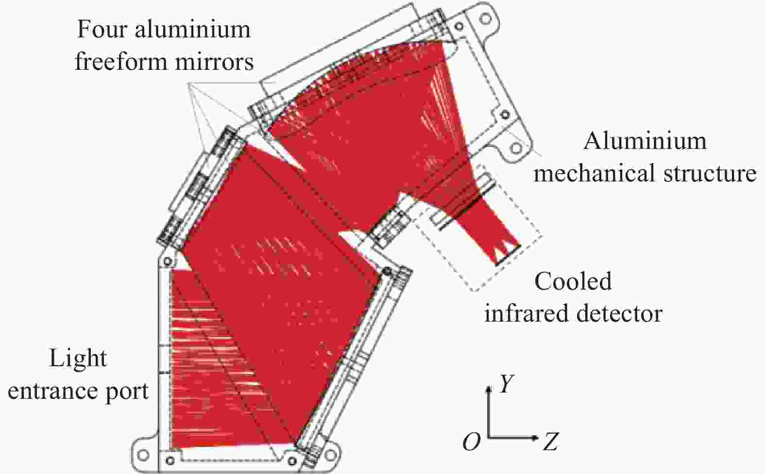
图 1 四反光机系统设计原理示意图
Figure 1. Design concept of the four mirror optical system
-
自由曲面面型复杂,具有多种多样的参数化表达形式,如XY多项式、Zernike多项式、Chebyshev多项式、Forbes多项式、Gaussian径向基函数、以及NURBS曲面等[9]。其中,XY多项式和Zernike多项式为常用自由曲面的表征形式。考虑到文中离轴四反光学系统关于YOZ平面对称,可只选择面型关于YOZ平面对称的基函数表征自由曲面,以减少优化变量,提高优化效率。因此,文中采用X偶次的XY多项式表征自由曲面,如公式(1)所示:
$$ z = \frac{{c{r^2}}}{{1 + \sqrt {1 - \left( {1 + k} \right){c^2}{r^2}} }} + \sum\limits_{i = 1}^N {{C_i}{{\left( {\frac{x}{{{R_m}}}} \right)}^{{m}}}{{\left( {\frac{y}{{{R_m}}}} \right)}^n}} $$ (1) 式中:z为自由曲面的面型矢高;(x, y)为自由曲面的孔径位置坐标;c为基面二次曲面的曲率;k为基面二次曲面的圆锥常数;r为自由曲面孔径的极径坐标;Rm为归一化半径;Ci为第i项XY子多项式的权重系数;m≥0;n≥0;1≤m+n。当光学系统优化时,将Ci作为优化变量,并逐渐增加子项数量,直到光学系统像质无明显改善。根据已有的设计和制造经验,文中设计选取XY多项式的最高次数为7,即1≤m+n≤7。
-
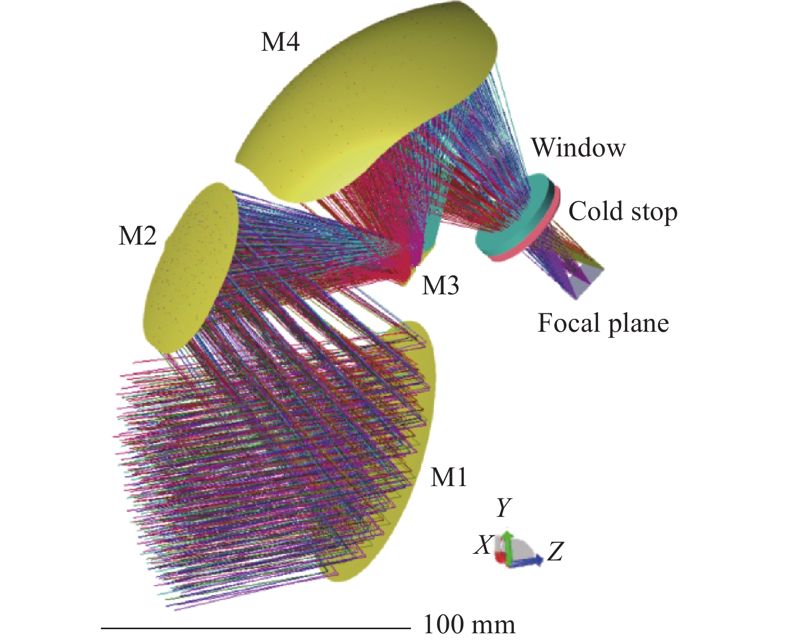
在自由曲面离轴四反光学系统优化设计过程中,输入条件为入瞳直径73 mm、视场角6.25°×5°,通过约束各视场主光线像高匹配探测器尺寸,通过约束出瞳位置和出瞳直径匹配探测器冷光阑及F数,设计得到的光学系统光路如图2所示。

图 2 光学系统光路结构
Figure 2. Layout of the optical system
反射镜M1与反射镜M2的间距为106.46 mm,反射镜M2与反射镜M3的间距为84.74 mm,反射镜M3与反射镜M4的间距为105.42 mm,反射镜M4与探测器窗口的间距为79.0 mm,出瞳与F#2制冷红外探测器的冷光阑完全匹配,出瞳距为28 mm、出瞳直径为Φ14 mm。在全局坐标系下,反射镜M1~M4绕X轴的倾斜角度分别为28.58°、34.72°、36.83°、72.19°。
-
反射镜M1~M4的有效通光孔径可通过反射镜M1~M4上的光线印记分布确定,如图3所示。反射镜M1的尺寸为Φ88 mm。反射镜M2的尺寸为59 mm×57 mm,图示中左上和右上角倒R27 mm圆角,左下和右下角倒R24 mm圆角。反射镜M3的尺寸为15 mm×18 mm,图示中四个角倒R2 mm圆角。反射镜M4的尺寸为94 mm×88 mm,图示中四个角倒R30 mm圆角。

图 3 反射镜M1~M4光线印记(不同颜色代表不同视场)
Figure 3. Ray footprint of each mirror M1-M4 (color for each field)
M1~M4的曲率半径R分别为−3334.59、401.06、−21.83、87.23 mm,圆锥常数都为0,各多项式子项权重系数如表2所示。
表 2 M1~M4各XY多项式子项权重系数
Table 2. XY polynomial coefficients of M1-M4
Term XY polynomial Coefficient of M1 Coefficient of M2 Coefficient of M3 Coefficient of M4 1 X0Y1 −1.91590e-02 −4.85671e-02 1.04008e-01 −9.21760e-02 2 X2Y0 −6.09199e-04 1.48764e-03 3.00154e-02 1.86876e-04 3 X0Y2 −7.87246e-04 6.40174e-04 2.82810e-02 −2.30088e-04 4 X2Y1 −8.05246e-06 −8.45861e-06 3.34959e-05 −3.48285e-06 5 X0Y3 −6.55433e-06 −1.09920e-05 2.33983e-06 −3.22347e-06 6 X4Y0 2.31375e-08 −8.36654e-09 9.54513e-06 7.97118e-09 7 X2Y2 2.95744e-08 −1.37912e-07 2.41580e-05 −1.39353e-08 8 X0Y4 1.02931e-08 −1.43957e-07 1.29804e-05 −1.63718e-08 9 X4Y1 −2.87921e-10 −8.54897e-10 −3.81025e-07 −2.18160e-10 10 X2Y3 −4.62580e-10 −3.00746e-09 3.11828e-09 −5.13363e-10 11 X0Y5 −1.89183e-10 −2.32407e-09 −3.87337e-08 −2.60893e-10 12 X6Y0 1.08579e-12 3.93228e-13 4.29815e-09 6.11019e-13 13 X4Y2 5.39421e-12 −7.60172e-12 6.35325e-08 −2.01506e-12 14 X2Y4 5.93096e-12 −3.12901e-11 3.73110e-08 −5.25985e-12 15 X0Y6 1.89380e-12 −2.73598e-11 1.60445e-08 −2.60015e-12 16 X6Y1 −3.74645e-14 −1.50798e-13 3.80074e-09 −5.13163e-14 17 X4Y3 −7.57945e-14 −2.30257e-13 2.12275e-10 −1.60806e-13 18 X2Y5 −6.16321e-14 −3.77989e-13 1.84473e-10 −1.35982e-13 19 X0Y7 −1.68419e-14 −2.20673e-13 3.74348e-10 −4.21283e-14 反射镜M1~M4减去最佳匹配球面之后的矢高残差分布如图4所示,具有明显的像散和彗差分量,与最佳匹配球面的最大矢高偏差分别是0.55、0.84、0.21、4.25 mm,即加工坯件是球面时的最大加工去除量分别是0.55、0.84、0.21、4.25 mm。
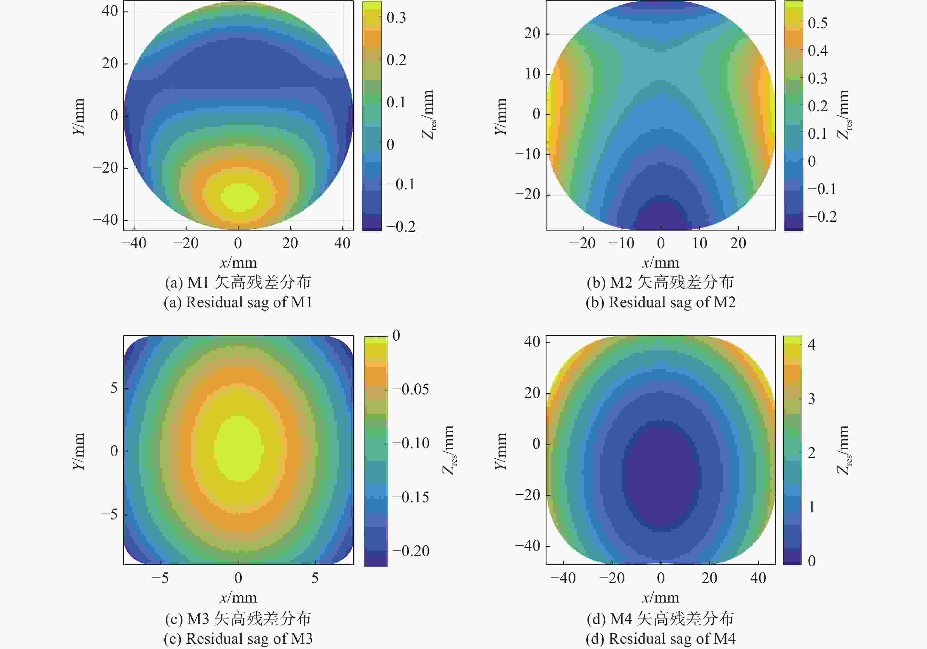
图 4 减去最佳匹配球面后各镜面矢高残差分布三维图
Figure 4. Residual sag distribution 3D diagram of each mirror after removing the best-fit sphere
-
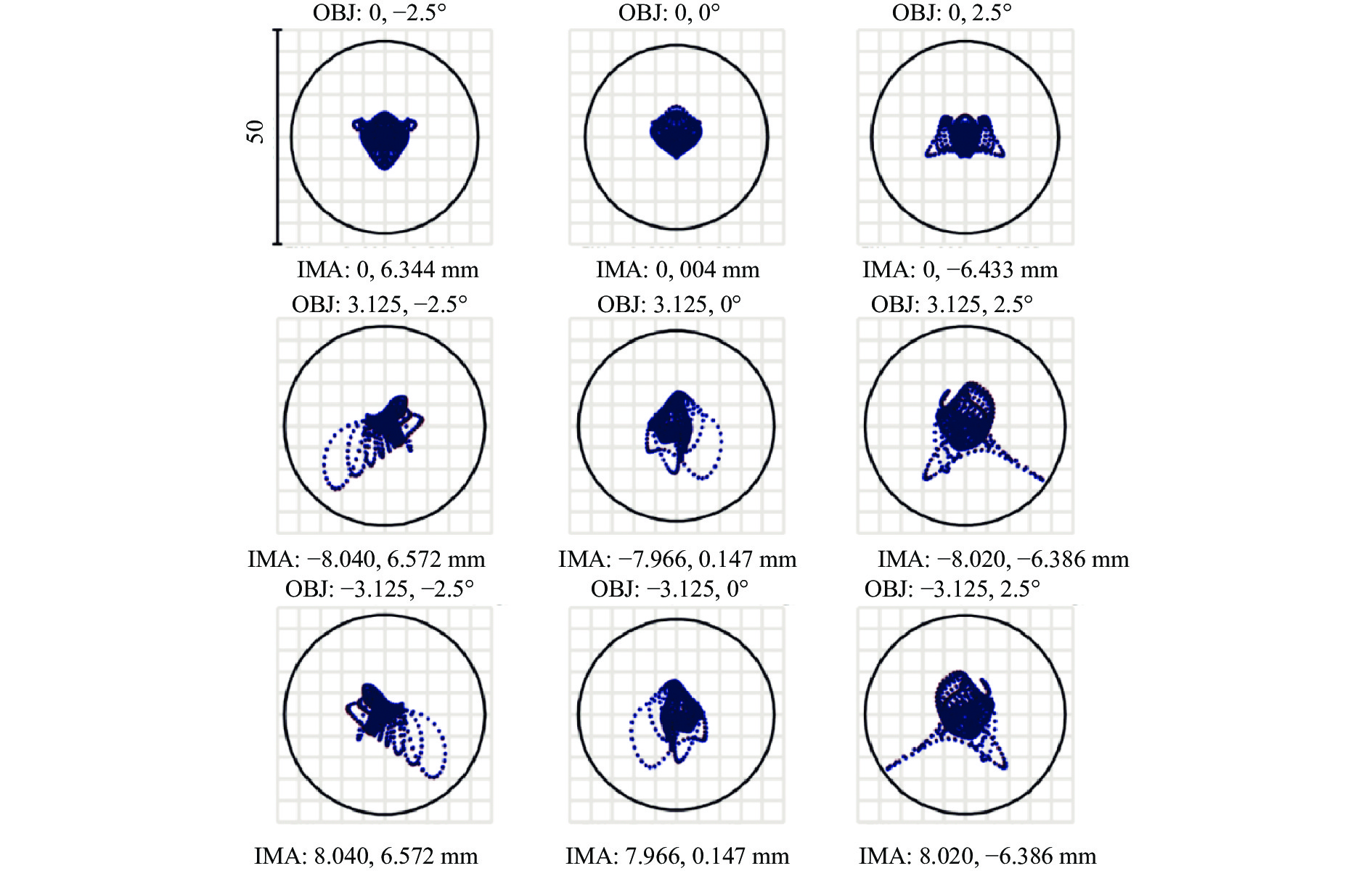
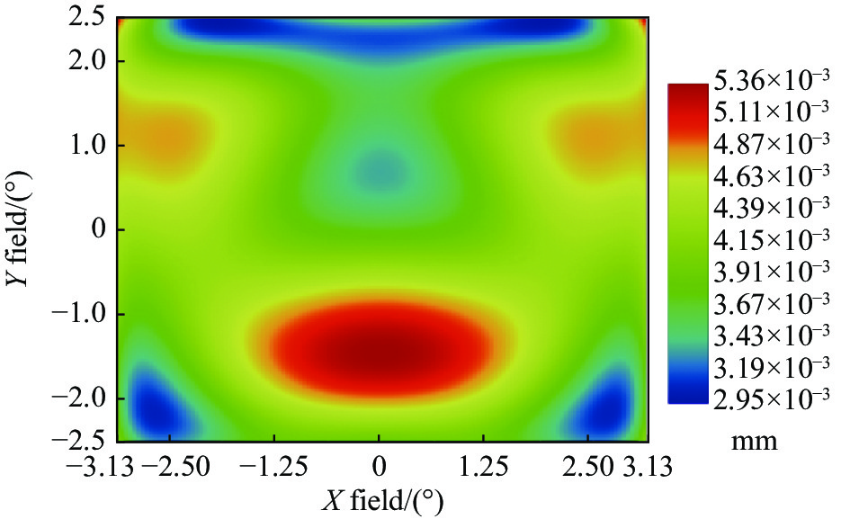
光学系统点列图和全视场RMS几何弥散斑半径分布分别如图5和图6所示,全视场最大RMS几何弥散斑半径为5.36 μm,远小于艾里斑直径21.4 μm,且远小于2倍像元尺寸即50 μm×50 μm,满足技术要求。

图 5 光学系统点列图
Figure 5. Spot diagram of the optical system

图 6 全视场RMS几何弥散斑半径分布
Figure 6. Full field RMS geometric spot radius distribution
-
光学系统全视场RMS波像差分布如图7所示,最大RMS波像差为0.037λ@8.85 μm,等效RMS 0.5λ@0.6328 μm。由于光学系统为全反射式,可采用0.6328 μm激光干涉仪对光学系统波像差进行测试,以对光学系统进行定量评价。

图 7 全视场RMS波像差分布
Figure 7. Full field RMS wavefront error distribution
-
光学系统传函如图8所示,在奈奎斯特频率20 lp/mm处光学系统传函≥0.48,接近衍射极限。

图 8 光学系统传函曲线
Figure 8. MTF curves of the optical system
-
光学系统畸变网格如图9所示,最大畸变~3%,满足技术要求。
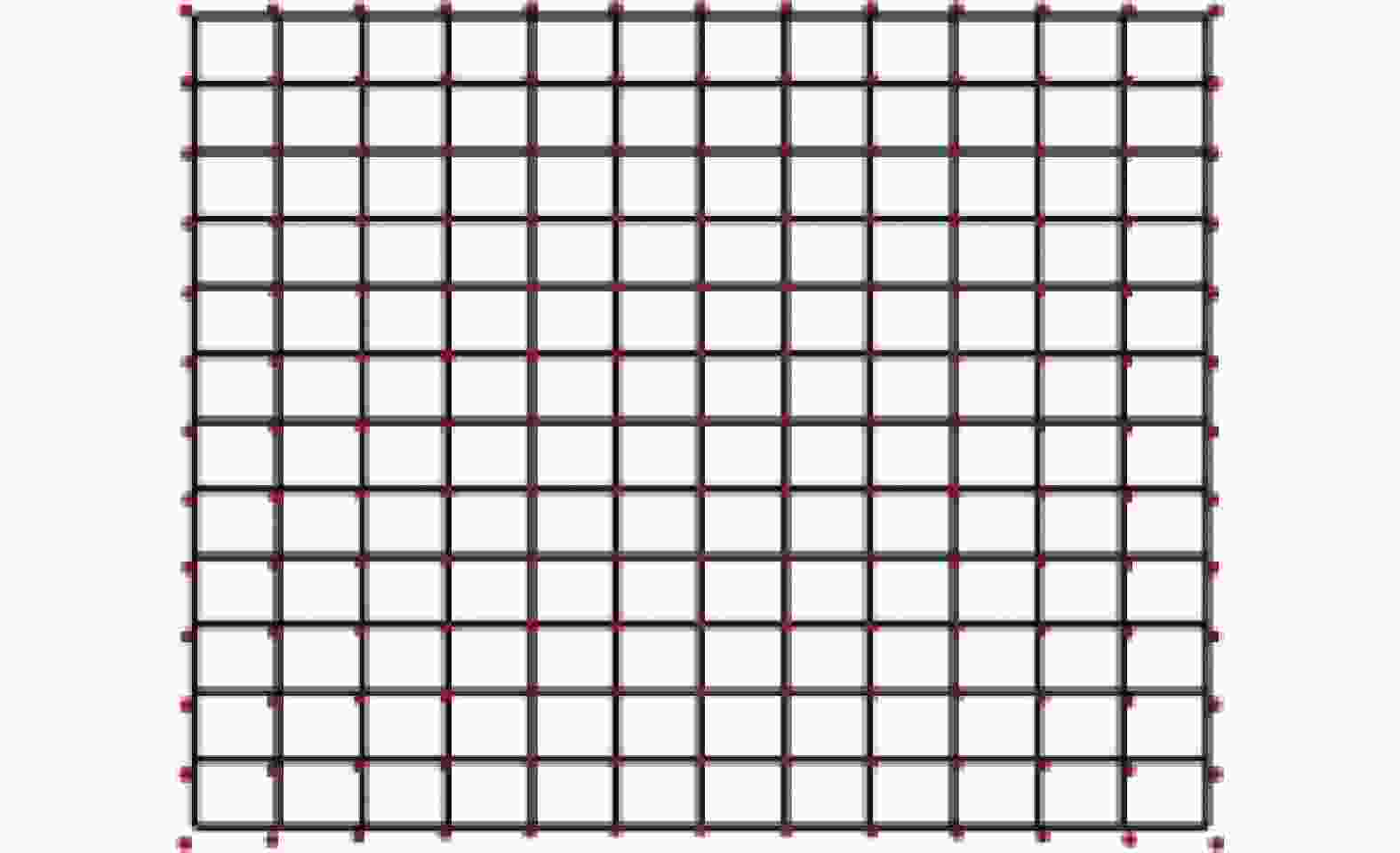
图 9 光学系统畸变网格
Figure 9. Distorted mesh of the optical system
-
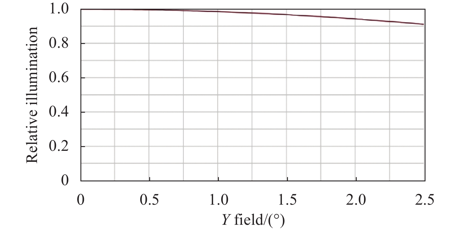
光学系统沿视场Y方向和X方向的相对照度分布曲线如图10和图11所示,Y方向照度均匀性优于91%,X方向照度均匀性优于87%。

图 10 沿Y方向相对照度分布
Figure 10. Relative illuminance along Y direction

图 11 沿X方向相对照度分布
Figure 11. Relative illuminance along X direction
-
由于自由曲面失去回转对称性[10],自由曲面系统装调难度增加,需要对装调公差进行分析。以光学系统几何弥散斑尺寸作为判据,得到各反射镜位姿公差分配结果如表3所示,四片反射镜的偏心公差为±20 μm、顶点间距公差为±0.05 mm、绕局部坐标X/Y/Z轴的倾斜公差为±1’。采用探测器轴向位置作为补偿,经过蒙特卡洛随机模拟,得到90%概率下RMS几何弥散斑直径为16.9 μm、最大RMS几何弥散斑直径为19.8 μm、平均RMS几何弥散斑直径为9.1 μm,均小于艾里斑直径,且远小于50 μm×50 μm的技术要求。
表 3 反射镜M1~M4装调位姿公差分配表
Table 3. Allocation table for positioning and attitude tolerance of M1-M4
No. Term Value No. Term Value 1 Detector position compensation ±2.00 mm 4 Distance between M3 and M4 ±0.05 mm 2 Distance between M1 and M2 ±0.05 mm 5 X-decenter of M1 ±0.02 mm 3 Distance between M2 and M3 ±0.05 mm 6 Y-decenter of M1 ±0.02 mm 7 X-tilt of M1 ±0.017° 16 Y-decenter of M3 ±0.02 mm 8 Y-tilt of M1 ±0.017° 17 X-tilt of M3 ±0.017° 9 Z-tilt of M1 ±0.017° 18 Y-tilt of M3 ±0.017° 10 X-decenter of M2 ±0.02 mm 19 Z-tilt of M3 ±0.017° 11 Y-decenter of M2 ±0.02 mm 20 X-decenter of M4 ±0.02 mm 12 X-tilt of M2 ±0.017° 21 Y-decenter of M4 ±0.02 mm 13 Y-tilt of M2 ±0.017° 22 X-tilt of M4 ±0.017° 14 Z-tilt of M2 ±0.017° 23 Y-tilt of M4 ±0.017° 15 X-decenter of M3 ±0.02 mm 24 Z-tilt of M4 ±0.017° -
光机结构设计应尽可能减小整机质量和尺寸,同时保证整机的强度和刚性。
离轴四反光机系统主要由四个自由曲面反射镜、支撑框架以及两侧盖板组成,如图12所示。反射镜和支撑结构均选用航天轻量化材料6061-T651铝合金,6061-T651材料特性如表4所示。虽然6061铝合金材料热膨胀系数较大,但是当反射镜和支撑结构的材料特性完全一致时,反射镜和支撑结构热变形等比例变化,可实现系统的光学无热化[11-12]。光机系统(包含探测器)包络尺寸为130.0 mm (X向)×225.6 mm (Y向)×251.0 mm (Z向),满足技术要求。
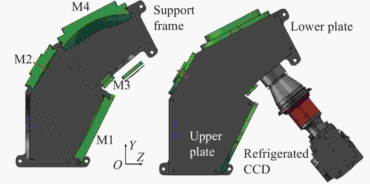
图 12 整体光机结构三维图
Figure 12. 3D model of system mechanical structure
表 4 6061-T6材料特性
Table 4. 6061-T6 material properties
Density/
kg·m3Thermal expansion coefficient
/KElastic modulus/
N·m−2Poisson's ratio Thermal conductivity
/W·(m·K)−12710 2.4E-5 6.9E10 0.33 154 -
反射镜和支撑结构均为铝合金,金属与金属之间通过螺钉连接属于刚性连接,刚性连接会对反射镜的镜面面形造成一定的损失[12-13]。为了减少这种影响,金属反射镜设计需要:(1)尽量使用柔性结构;(2)反射镜设计成比安装结构更刚性的刚性体;(3)在加工制造期间与工作期间使用同样的方法夹持反射镜;(4)安装表面应当加工成平面,与光学表面有同样精度并平行于光学表面。
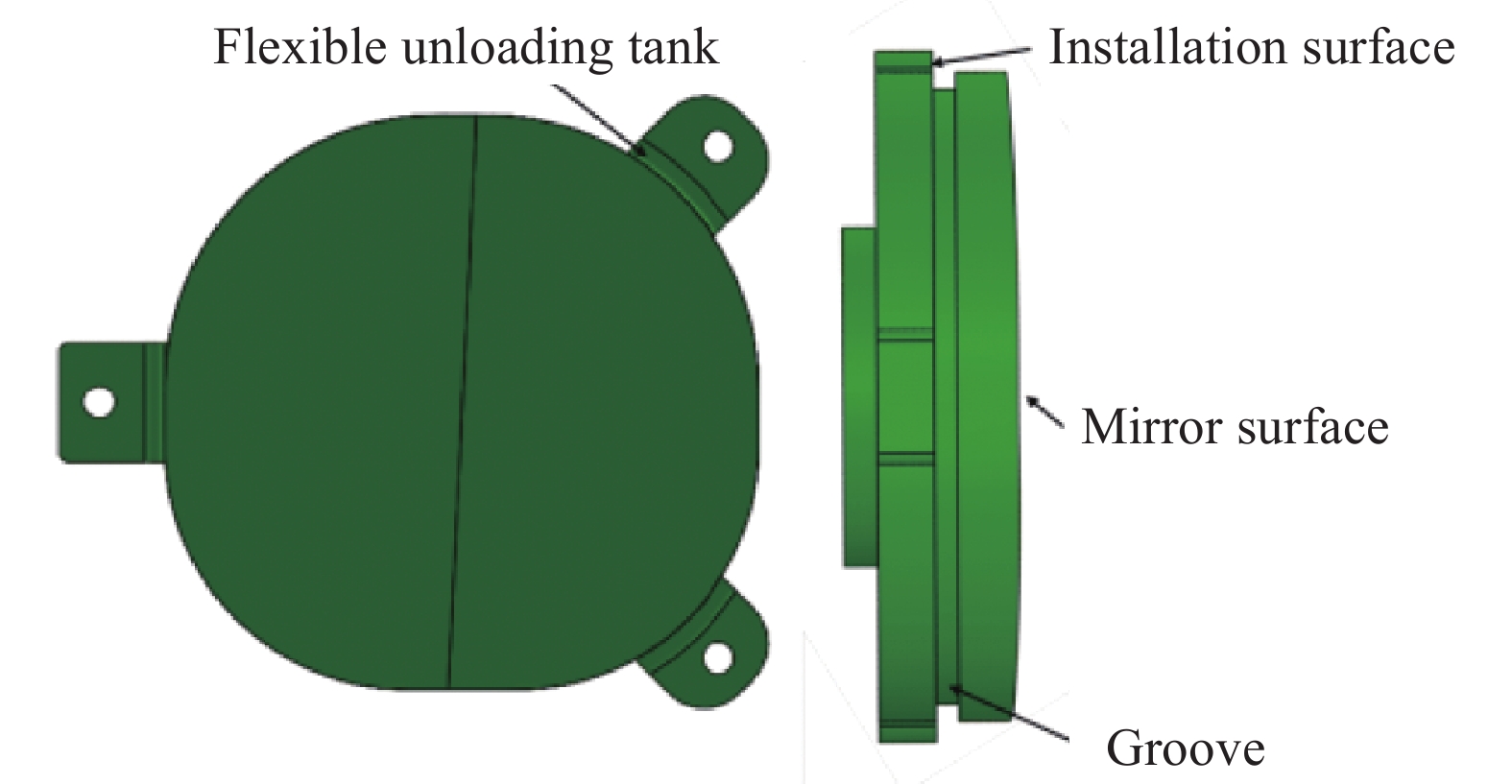
以反射镜M2为例,根据金属反射镜的设计原则,对反射镜M2进行结构设计。反射镜M2的尺寸为59 mm×57 mm,中心厚度为10 mm。在反射镜背面设计三耳结构,三耳结构靠近反射镜面位置带有柔性卸载槽,三耳结构上通孔用于加工时与加工基板固连,也作为反射镜与支撑框架固连的接口,反射镜面和安装平面之间使用凹槽隔开,反射镜M2三维模型如图13所示。

图 13 反射镜M2集成式柔性三维模型
Figure 13. Integrated flexible 3D structure of M2
-
为了验证整机无热化特点,对系统进行光机热集成分析,分析过程如下。
(1)建立光机有限元模型;
(2)加载温度边界条件,得到镜面和焦面变形数据(含刚体位移);
(3)将变形数据进行拟合,并导入光学设计软件进行仿真分析,计算得到不同温度边界下的光学成像性能。
以工作温度由20 ℃基准温度变化至30 ℃时的光机热集成分析为例。使用四面体网格对光机模型进行网格划分,在安装底板底部四个孔位添加固定约束,然后对整机施加30 ℃的温度边界,如图14所示。

图 14 有限元模型及边界条件
Figure 14. Boundary conditions of the finite element model
有限元分析计算得到四个反射镜和焦面X、Y、Z三个方向的变形数据,将变形数据拟合成分段B样条曲面并代入光学设计软件中,如图15所示。

图 15 变形数据代入光学设计软件
Figure 15. The deformation datas of the mirrors and focal plane are imported into the optical software
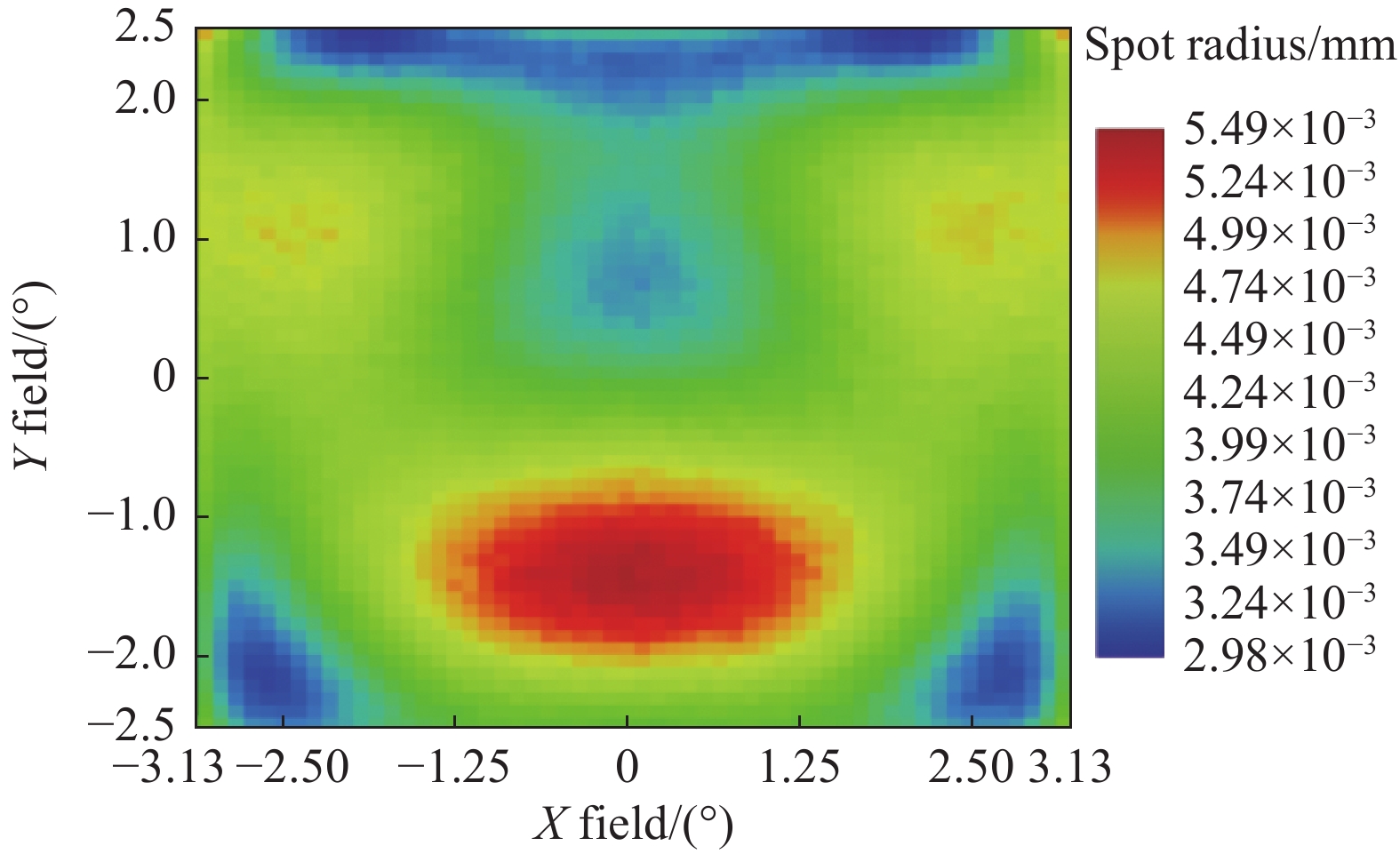
对引入变形后的光学系统进行仿真分析,得到30 ℃时光学系统的全视场RMS几何弥散斑半径分布,如图16所示。全视场最大RMS几何弥散斑半径为5.49 μm,接近基准工作温度20 ℃下的全视场最大RMS几何弥散斑半径5.36 μm,证明了光机系统无热化效果较好。
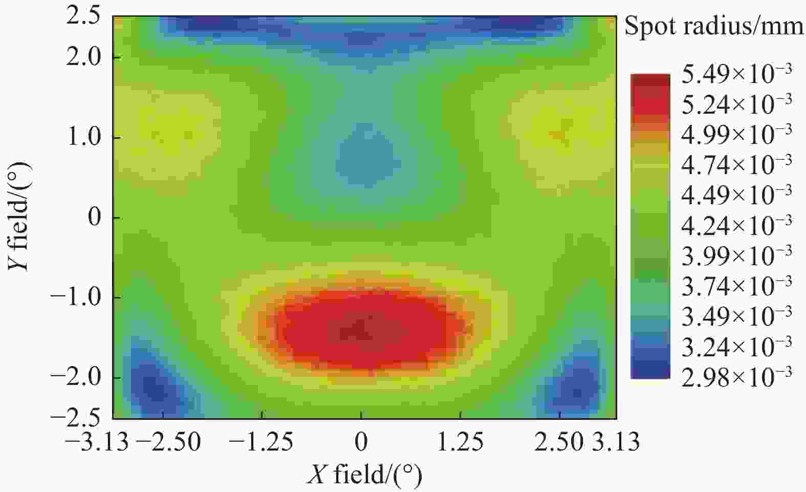
图 16 全视场RMS几何弥散斑半径分布
Figure 16. Full field RMS geometric spot radius distribution
-
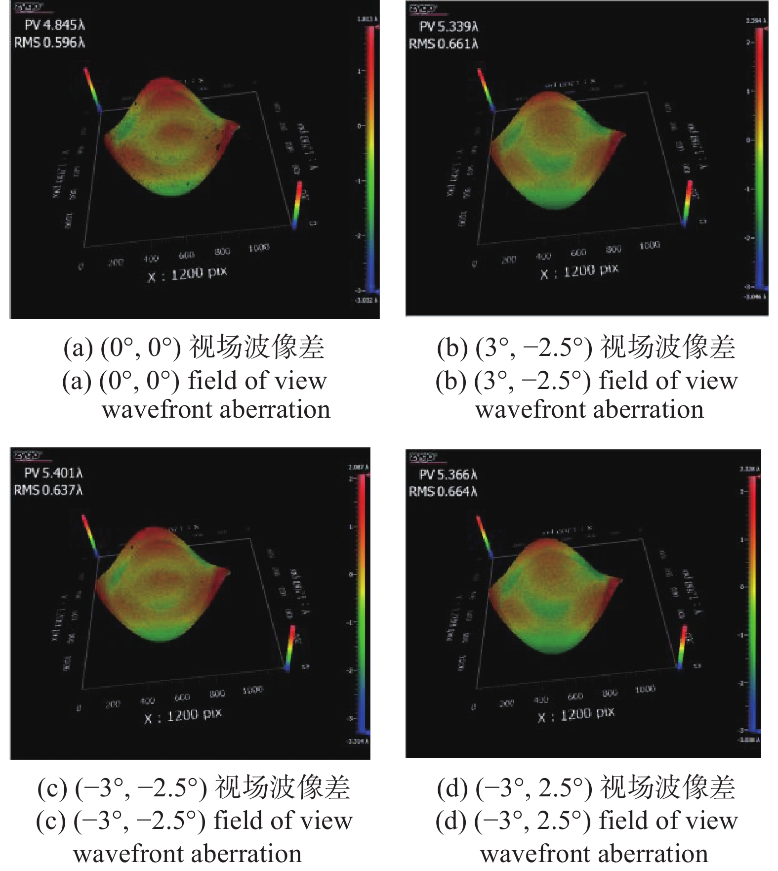
自由曲面反射镜和支撑结构件加工完成后,基于计算机辅助装调方法,以系统波像差为判据,对自由曲面离轴四反系统进行装调。使用干涉仪对装调完成后的光机系统进行波像差测试,测试光路如图17(a)所示。典型视场的系统波像差分布如图18所示,波像差<RMS 0.7λ@632.8 nm,等效RMS 0.05λ@8.85 μm,达到衍射极限,满足了设计要求。光机系统的焦距为146.2 mm,基于国产制冷红外探测器测试得到整机等效噪声温差(NETD)为26.8 mK。对5 km处的建筑物外景进行了拍摄,拍摄得到的外红外图像如图17(b)所示,像质良好。

图 17 系统波前测试光路(a)与外景图像拍摄(b)
Figure 17. Wavefront testing optical path (a) and test photographic (b) of the system

图 18 典型视场波像差
Figure 18. Wavefront aberration of typical field of view
-
设计了一款带有实出瞳的全自由曲面全铝光机离轴四反红外探测系统,采用7次XY多项式表征自由曲面完成了光学系统的优化设计,对光学系统全视场几何弥散斑、波像差、光学传函、畸变网格、镜面面型、装调公差等进行了分析,证明光学系统设计结果满足红外探测的技术要求。光机系统采用了全铝光机设计,其中铝合金自由曲面反射镜采用三耳柔性支撑方式以减少刚性连接应力,对光机系统进行了光机热集成分析,验证了光机系统的无热化效果。完成了光机系统装配,并对光机系统进行了全视场波像差测试,全视场RMS波像差<0.7λ@632.8 nm,满足长波红外探测技术要求。
Freeform off-axis four-mirror all-aluminum infrared detection system (invited)
-
摘要: 为满足红外探测系统对大视场、轻量化、低成本的需求,设计并研制了一款用于制冷型红外探测器的自由曲面离轴四反全铝光机系统。光学设计采用具有实出瞳的离轴无遮拦全反射式光路形式,并利用7次XY多项式表征各反射镜面型。在紧凑包络约束下,实现了6.25°×5°的视场角,全视场RMS几何弥散斑半径<6.0 μm。各反射镜和支撑结构材料均选用6061-T651铝合金,各反射镜进行了柔性支撑设计,以降低装调时的刚性连接应力。采用激光干涉仪对光机系统波像差进行了测试,典型视场波像差<RMS 0.7λ@632.8 nm。相比传统的离轴反射系统,文中系统采用“全自由曲面+全铝光机”新构型,能够用更紧凑的包络实现更大视场,且整机具有轻量化、低成本以及无热化的特点,在红外探测领域具有重要应用前景。Abstract:
Objective Infrared detection technology has the advantage of passive thermal radiation detection and continuous work day and night. It can greatly reduce the restriction of environmental factors such as the light conditions. It is widely used in ecological environment monitoring, night vision detection, precision guidance and other fields. In recent years, with the development of infrared detection technology, especially in the field of aviation and aerospace remote sensing, in order to improve the timeliness of infrared remote sensing detection and realize the large-scale deployment of infrared detection system, the demand for large-field-of-view, high-compact, lightweight and low-cost infrared detection system is becoming more and more urgent. For this purpose, a freeform off-axis four-mirror all-aluminum infrared optical detection system with a large field of view and a compact package is designed in this paper. Methods A freeform off-axis four-mirror all-aluminum infrared optical detection system is designed and built in this paper. The optical system has a real exit pupil to connect the cold aperture of a cooled infrared detector (Fig.2). The 7th order XY polynomials is used to represent the surface of the four freeform mirrors. The full-field geometric spot radius, wave aberration, modulation transfer function, and distortion grid are analyzed (Fig.5-9). The Monte Carlo algorithm is used for tolerance analysis to determine the influence of the alignment errors of the four mirrors (Tab.3). The optical system adopts an all-aluminum optomechanical design (Fig.12), in which the aluminum freeform mirror employs a three-ear flexible support mode to reduce the rigid connection stress (Fig.13). The optical, mechanical and thermal integration analysis is carried out, and the athermal effect of the optical system is verified (Fig.14-16). The optical system is assembled, and the full-field wave aberration is measured (Fig.17-18). Results and Discussions The optimized freeform off-axis four-mirror optical system has a large field of view of 6.25°×5°. The maximal geometric spot radius over the whole field of view is 5.36 μm, which is far less than the radius of the airy spot (Fig.5-6). The full-field wavefront error is less than 0.037λ@8.85 μm, which approaches the diffraction limit (Fig.7). The minimal MTF at 20 lp/mm is 0.48 (Fig.8). Considering the conventional alignment errors of the four mirrors (Tab.3), the geometric spot radius of the optical system is expect to be less than 19.8 μm. According to the optical, mechanical and thermal integration analysis, the maximal full-field geometric spot radius is slightly changed from 5.36 μm to 5.49 μm when the working temperature is changed from 20 ℃ to 30 ℃ (Fig.16). The result proves that the all-aluminum optomechanical system potentially has the optically athermal characteristics. The prototype has a focal length of 146.2 mm and a NETD of 26.8 mK. The measured wavefront error of the prototype is less than RMS 0.7λ@632.8 nm, which meets the technical requirements (Fig.18). Conclusions A freeform off-axis four-mirror all-aluminum infrared optical system with a real exit pupil, a large field of view and a compact package is built in this paper. The optical system has a field of view of 6.25°×5°. The designed full-field geometric spot radius, wavefront error and modulation transfer function all approach the diffraction limit. The tolerance analysis of the alignment errors of the four mirrors is carried out based on the Monte Carlo algorithm, which leads to a full-field geometric spot radius of less than 19.8 μm. The optical system adopts an all-aluminum optomechanical design, which naturally possesses an optically athermal potentiality. The optical, mechanical and thermal integration analysis for a temperature rise of 10 ℃ of the optical system verifies the optical athermality of the optical system. The measured full-field wavefront error of the prototype is less than RMS 0.7λ@632.8 nm. The captured far field infrared image shows the high performance of the prototype. Compared with the traditional off-axis reflective optical system, the demonstrated optical system adopts a new configuration of "all-freeform optical surfaces + all-aluminum optomechanics". It can achieve a larger field of view with a more compact envelope. And, the system has the characteristics of lightweight, low cost and optical athermality, which has important application prospects in the field of infrared detection. -
图 3 反射镜M1~M4光线印记(不同颜色代表不同视场)
Figure 3. Ray footprint of each mirror M1-M4 (color for each field)
图 4 减去最佳匹配球面后各镜面矢高残差分布三维图
Figure 4. Residual sag distribution 3D diagram of each mirror after removing the best-fit sphere
图 15 变形数据代入光学设计软件
Figure 15. The deformation datas of the mirrors and focal plane are imported into the optical software
图 17 系统波前测试光路(a)与外景图像拍摄(b)
Figure 17. Wavefront testing optical path (a) and test photographic (b) of the system
表 1 系统设计指标
Table 1. Specification of the optical system
Parameter Specifications Resolution/pixel 640×512 Pixel size/μm2 25×25 Spectral band/μm 7.7-10.0 Entrance pupil diameter/mm 73 F-number 2 Field of view/(°) 6.25×5.0 Distortion <5% RMS spot size/μm <50×50 RMS wavefront error <1λ@632.8 nm Package size/mm3 <150×250×300 Working temperature/℃ 10-30  下载: 导出CSV
表 2 M1~M4各XY多项式子项权重系数
Table 2. XY polynomial coefficients of M1-M4
Term XY polynomial Coefficient of M1 Coefficient of M2 Coefficient of M3 Coefficient of M4 1 X0Y1 −1.91590e-02 −4.85671e-02 1.04008e-01 −9.21760e-02 2 X2Y0 −6.09199e-04 1.48764e-03 3.00154e-02 1.86876e-04 3 X0Y2 −7.87246e-04 6.40174e-04 2.82810e-02 −2.30088e-04 4 X2Y1 −8.05246e-06 −8.45861e-06 3.34959e-05 −3.48285e-06 5 X0Y3 −6.55433e-06 −1.09920e-05 2.33983e-06 −3.22347e-06 6 X4Y0 2.31375e-08 −8.36654e-09 9.54513e-06 7.97118e-09 7 X2Y2 2.95744e-08 −1.37912e-07 2.41580e-05 −1.39353e-08 8 X0Y4 1.02931e-08 −1.43957e-07 1.29804e-05 −1.63718e-08 9 X4Y1 −2.87921e-10 −8.54897e-10 −3.81025e-07 −2.18160e-10 10 X2Y3 −4.62580e-10 −3.00746e-09 3.11828e-09 −5.13363e-10 11 X0Y5 −1.89183e-10 −2.32407e-09 −3.87337e-08 −2.60893e-10 12 X6Y0 1.08579e-12 3.93228e-13 4.29815e-09 6.11019e-13 13 X4Y2 5.39421e-12 −7.60172e-12 6.35325e-08 −2.01506e-12 14 X2Y4 5.93096e-12 −3.12901e-11 3.73110e-08 −5.25985e-12 15 X0Y6 1.89380e-12 −2.73598e-11 1.60445e-08 −2.60015e-12 16 X6Y1 −3.74645e-14 −1.50798e-13 3.80074e-09 −5.13163e-14 17 X4Y3 −7.57945e-14 −2.30257e-13 2.12275e-10 −1.60806e-13 18 X2Y5 −6.16321e-14 −3.77989e-13 1.84473e-10 −1.35982e-13 19 X0Y7 −1.68419e-14 −2.20673e-13 3.74348e-10 −4.21283e-14
下载: 导出CSV
表 3 反射镜M1~M4装调位姿公差分配表
Table 3. Allocation table for positioning and attitude tolerance of M1-M4
No. Term Value No. Term Value 1 Detector position compensation ±2.00 mm 4 Distance between M3 and M4 ±0.05 mm 2 Distance between M1 and M2 ±0.05 mm 5 X-decenter of M1 ±0.02 mm 3 Distance between M2 and M3 ±0.05 mm 6 Y-decenter of M1 ±0.02 mm 7 X-tilt of M1 ±0.017° 16 Y-decenter of M3 ±0.02 mm 8 Y-tilt of M1 ±0.017° 17 X-tilt of M3 ±0.017° 9 Z-tilt of M1 ±0.017° 18 Y-tilt of M3 ±0.017° 10 X-decenter of M2 ±0.02 mm 19 Z-tilt of M3 ±0.017° 11 Y-decenter of M2 ±0.02 mm 20 X-decenter of M4 ±0.02 mm 12 X-tilt of M2 ±0.017° 21 Y-decenter of M4 ±0.02 mm 13 Y-tilt of M2 ±0.017° 22 X-tilt of M4 ±0.017° 14 Z-tilt of M2 ±0.017° 23 Y-tilt of M4 ±0.017° 15 X-decenter of M3 ±0.02 mm 24 Z-tilt of M4 ±0.017°
下载: 导出CSV
表 4 6061-T6材料特性
Table 4. 6061-T6 material properties
Density/
kg·m3Thermal expansion coefficient
/KElastic modulus/
N·m−2Poisson's ratio Thermal conductivity
/W·(m·K)−12710 2.4E-5 6.9E10 0.33 154
下载: 导出CSV
-
[1] 李加洪. 航空遥感技术系统在某些灾害监测中的应用[J]. 遥感技术与应用, 1996, 11(2): 32-38. doi: 10.3788/IRLA20210905 [2] Kampe T U, McCorkel J, Hamlin L, et al. Progress in the development of airborne remote sensing instrumentation for the National Ecological Observatory Network [C]//Remote Sensing and Modeling of Ecosystems for Sustainability VIII, Proc SPIE, 2011, 8156: 81560A. [3] Ohgi N, Iwasaki A, Kawashima T, et al. Japanese hyper-multi spectral mission [C]//2010 IEEE International Geoscience and Remote Sensing Symposium, Honolulu, HI USA, 2010: 3756-3759. [4] 姜晰文, 贾学志, 丛杉珊. 自由曲面在制冷型离轴三反光学系统的应用[J]. 红外与激光工程, 2018, 47(9) : 0918004-1-0918004-7 doi: 10.3788/IRLA201847.0918004. Jiang Xiwen, Jia Xuezhi, Cong Shanshan. Application of freeform surfaces in cooled off-axis thre-mirror optical system [J]. Infrared and Laser Engineering, 2018, 47(9): 0918004. (in Chinese) doi: 10.3788/IRLA201847.0918004 [5] 李旭阳, 倪栋伟, 杨明洋. 基于自由曲面的大视场空间相机光学系统设计[J]. 光子学报, 2018, 47(9): 0922003-1-0922003-9 doi:10.3788-gzxb20184709.0922003. Li Xuyang, Ni Dongwei, Yang Mingyang. Design of optical system for large field of view space camera based on free-form ssurface [J]. Acta Photonica Sinica, 2018, 47(9): 0922003. (in Chinese) doi: 10.3788/gzxb20184709.0922003 [6] 赵宇宸, 何欣, 张凯, 刘强, 崔永鹏, 孟庆宇. 轻小型大视场自由曲面离轴光学系统设计[J]. 红外与激光工程, 2018, 47(12): 1218001-1-1218001-7. doi: 10.3788/IRLA201847.1218001 Zhao Yuchen, He Xin, Zhang Kai, et al. Optical design of miniaturized and large field of view off-axis optical system based on freeform surface [J]. Infrared and Laser Engineering, 2018, 47(12): 1218001. (in Chinese) doi: 10.3788/IRLA201847.1218001 [7] Xie Yongjun, Mao Xianglong, Li Jinpeng, et al. Optical design and fabrication of an all-aluminum unobscured two-mirror freeform imaging telescope [J]. Appl Opt, 2020, 59: 833-840. doi: https://doi.org/10.1364/AO.379324 [8] Matthias Beier, Johannes Hartung, Thomas Peschel, et al. Development, fabrication, and testing of an anamorphic imaging snap-together freeform telescope [J]. Appl Opt, 2015, 54: 3530-3542. doi: https://doi.org/10.1364/AO.54.003530 [9] 杨通, 段璎哲, 程德文, 王涌天. 自由曲面成像光学系统设计: 理论、发展与应用[J] . 光学学报, 2021, 47(1): 0108001-1-0108001-29. doi: 10.3788/AOS202141.0108001 Yang Tong, Duan Yinzhe, Cheng Dewen, et al. Freeform imaging optical system design: theories, development, and application [J]. Acta Optica Sinica, 2021, 41(1): 0108001. (in Chinese) doi: 10.3788/AOS202141.0108001 [10] 王超, 张新, 王灵杰等. 离轴自由曲面三镜反射系统的装调技术[J]. 光学学报, 2012, 33(12), 1208001-1-1208001-7. doi: 10.3788/AOS201333.1208001 Wang Chao, Zhang Xin, Wang Lingjie, et al. Adjustment of three-mirror off-axis freeform system [J]. Acta Optica Sinica, 2013, 33(12): 1208001. (in Chinese) doi: 10.3788/AOS201333.1208001 [11] 王建鹏. 铝材料光学系统光机设计及其力热特性分析[D]. 国防科技大学, 2018. Wang Jianpeng. The opto-mechanical design of aluminum optical system and analysis of its thermal characteristics[D]. Changsha: National University of Defense Technology, 2018. (in Chinese) [12] Gao Rong, Li Jinpeng, Wang Peng, et al. The opto-mechanical–thermal coupling analysis and verification of an all-aluminum freeform imaging telescope [J]. Symmetry, 2022, 14: 2391. doi: 10.3390/sym14112391 [13] Zhao Zhiceng, Chen Xinhua, Shen Weimin. Design, fabrication, and testing of an all-metal ultra-compact telescope [J]. Appl Opt, 2022, 61: 7767-7775. doi: https://doi.org/10.1364/AO.466055 -

 点击查看大图

计量
- 文章访问数: 240
- HTML全文浏览量: 55
- PDF下载量: 80
- 被引次数: 0

