


 下载:
下载:


-
光学成像技术可获得直观、高分辨率的图像信息,便于海底目标识别和详查。在水下低照度环境下,通常采用主动光源进行照明,但在水体浑浊度较高时,受水体吸收和散射作用影响,水下光学成像存在工作距离近、图像信噪比低的问题。随着海底资源开发、海洋生态监测、海洋渔业评估、水下考古、搜索救援等水下作业需求的日益增高,对水下光学成像提出了更高要求:远距离、高分辨率、高信噪比成像。如何实现高性能的水下光学成像成为研究热点和难点。
水下光学图像模糊主要来源于水体散射噪声。整体上,水体散射包括前向散射和后向散射,其中后向散射会降低图像信噪比和对比度 [1],前向散射主要影响图像的空间分辨率。相比前向散射,后向散射对水下光学图像的影响更为突出。相比传统水下光学成像,距离选通成像技术[2-5]在抑制后向散射方面具有明显效果。距离选通成像技术是一种主动激光成像技术,通过对目标进行选通切片成像,可减小后向散射噪声。选通切片的景深影响后向散射噪声的抑制效果,其景深大小与激光脉宽和选通门宽有关,通常切片景深越小,水体后向散射噪声越小。为降低水体后向散射噪声,需压窄选通切片景深,但这会影响大景深目标的观测。因此,在大切片景深下如何进一步抑制后向散射成为研究重点。
不同于距离选通成像,光学偏振成像技术可利用目标反射光和后向散射光之间的偏振差异来过滤后向散射噪声[6-8]。鉴于此,秦琳将光学偏振成像与距离选通成像结合[9],利用光学偏振成像进一步去除距离选通成像中的后向散射噪声,证明了偏振选通成像的可行性,但其并未建立和分析成像物理模型,且受室内环境限制,对衡量自然水体中成像距离的参考意义不大。文中在建立偏振选通物理模型的基础上,通过不同水质下距离选通成像(简称“选通成像”)和偏振距离选通成像(简称“偏振选通成像”)的对比研究,分析距离选通成像和偏振选通成像的水下目标探测的适用条件。
-
图1为水下偏振距离选通成像物理模型示意图。如图1(a)所示,典型的水下偏振距离选通成像系统主要由脉冲激光器、门控成像器件、起偏器、光学发射镜头、检偏器、光学接收镜头、时序控制器(TCU)等组成。工作过程中,TCU控制脉冲激光器和门控成像器件ICMOS按照设计的选通时序工作。其中,脉冲激光器发出激光脉冲,通过起偏器起偏后产生线偏振光,并由光学发射镜头整形后产生所需的偏振脉冲光,偏振脉冲光经目标反射后产生含有目标偏振信息的回波信号;在设定延时下,ICMOS开启选通快门,接收由光学接收镜头采集并由检偏器过滤的目标信号,利用选通空间滤波抑制选通切片与成像系统间传输链路上水体后向散射噪声,并利用偏振滤波进一步抑制选通切片内水体后向散射噪声,实现水下光学图像信噪比和对比度的提升。图1(b)对比示意了成像过程中传统水下光学成像、选通成像和偏振选通成像接收目标信号、水体噪声和背景噪声的差异。传统水下光学成像包含了整个链路上全部的噪声和目标信号,具体包括目标与成像系统间的主要后向散射噪声(main backscatter)、目标附近的残留噪声(sub-backscatter)、目标信号、水体背景噪声;相比传统水下光学成像,选通成像则有效过滤了目标与成像系统间的主要后向散射噪声和水体背景噪声,但是选通图像中还存在选通切片内的残留后向散射噪声;相比选通成像,将光学偏振成像引入选通成像后,偏振选通成像则可进一步抑制选通图像中的残留噪声。需说明的是,成像系统自身噪声在各成像技术中均存在,因此在图1(b)中均未单独示意。偏振选通成像虽然可以进一步抑制选通图像中的残留噪声,但由于起偏器和检偏器对光能量存在衰减,因此在实际应用中,不同水质下选通成像和偏振选通成像需对比研究,以明确适用条件。

图 1 水下偏振选通成像示意图
Figure 1. Schematic diagram of underwater PRGI
王新伟[10]和葛卫龙[11]等对选通成像目标光能量进行了计算,相机接收到的距离r处的目标能量:
$$ E_{r}= \frac{{\rho f}_{L}}{{f}_{C}}{\eta }_{r}{\eta }_{t} \left(\frac{D}{2r}\right)^2 {{\rm{e}}}^{-2cr}\cdot{\int }_{0}^{\mathrm{\infty }}\frac{G\left(t\right)Q\left(t\right)}{{t}_{p}}{\rm{d}}t $$ (1) 式中:fL为脉冲激光重复频率;fC为相机帧频;ρ为水下目标(视为朗伯体)的反射率;G(t)为激光函数;D为接收光学系统直径;ηr和ηt为发射和接收光学系统的效率;Q(t)为门函数;c为水体衰减系数;tp为脉冲宽度。
在对目标信号光进行计算后,需要对水体后向散射光能量进行计算。王新伟[10]和李丽等[12]计算了选通成像过程中的后向散射光能量,综合上述研究成果,文中给出后向散射光能量为:
$$ E_{b}= \frac{{f}_{L}}{{f}_{C}}\left(\frac{D}{2}\right)^2 \sigma \eta_{r}\eta _{t} {\int }_{0}^{\infty }{\int }_{\tfrac{{V}_{w}\left({\tau }_{d}-{t}_{p}\right)}{2}}^{\tfrac{{V}_{w}\left({\tau }_{d}+{t}_{g}\right)}{2}}\frac{{G\left(t\right)Q\left(t\right){\rm{e}}}^{-2cr}}{{\tau }_{p}r^2}{\rm{d}}t{\rm{d}}r $$ (2) 式中:σ为水体后向散射系数;Vw为水中光速;τd为开门时刻(延时);tg为选通门宽。G(t)和Q(t)取值如下:
$$ G(t)= \left\{\begin{array}{c}G,\;{\tau }_{d} \leqslant t \leqslant {{\tau }_{d}+t}_{g}\\ 0,\;{\rm{else}}\;{{t}}\end{array}\right. $$ (3) $$ Q(t)= \left\{\begin{array}{c}Q,\;{\tau }_{d}\leqslant t \leqslant {{\tau }_{d}+t}_{g}\\ 0,\;{\rm{else}}\;{{t}}\end{array}\right. $$ (4) 式中:G为相机增益;Q为激光单脉冲能量。
偏振选通成像无法过滤切片内的前向散射光,在高浑浊水体中,前向散射光对成像质量影响严重,因此,文中在建立偏振选通成像物理模型时计算前向散射光能量[13]:
$$ E_{f}= \dfrac{{f}_{L}}{{f}_{c}}{\eta }_{r}{\eta }_{t}{\int }_{{t}_{g}}^{{t}_{g}+{\tau }_{d}}{\int }_{\tfrac{{V}_{w}\left({\tau }_{d}-{t}_{p}\right)}{2}}^{\tfrac{{V}_{w}\left({\tau }_{d}+{t}_{g}\right)}{2}}\frac{\pi {D}^{4}G\left(t\right)Q\left(t\right)\beta \left(\theta \right)\rho {{\rm{e}}}^{-2cr}}{16{\tau }_{p}r^2r{'}^2} {\rm{d}}t {\rm{d}}r' $$ (5) 式中:r′为前向散射体积元距相机距离。体积散射函数采用Henyey-Greenstein 函数:
$$ \beta(\theta)=\frac{b}{4 \pi}\left(1-g^2\right)\left(1+g^2-2 g \cos \theta\right)^{-{2}/{3}} $$ (6) 式中:b为总散射系数;g为非对称因子。取b=0.45c,g=0.8,前向截获因子取1[14-15]。
距离选通成像信噪比如下:
$$ S NR_{RGI}= \frac{{E}_{r}}{{{E}_{d}+E}_{b}+{E}_{f}} $$ (7) 式中:Ed为系统噪声功率。
当水体散射系数低于0.5 mm−1时,532 nm线偏振光入射水体时产生的后向散射光的线偏振度随散射系数的增加呈e指数衰减,圆偏振度呈e指数上升[16-17]。假设线偏振度为DOPl,圆偏振度为DOPc,已知检偏器可以过滤100%的线偏振态后向散射光和50%的圆偏振态后向散射光。单个偏振器的光衰减为50% [18],定义偏振选通信噪比如下:
$$ S N R_{PRGI}= \frac{0.25{E}_{r}}{0.25[\left(1-0.5{DOP}_{c}-{DOP}_{l}\right){E}_{b}+{E}_{f}]+{E}_{d}} $$ (8) 化简后可得:
$$ S N R_{PRGI}= \frac{{E}_{r}}{\left(1-0.5{DOP}_{c}-{DOP}_{l}\right){E}_{b}+{E}_{f}+4{E}_{d}} $$ (9) 由于较难获得准确的水体后向散射光偏振度数据,假设当水体散射系数远低于0.5 mm−1时,后向散射光的线偏振度近似为1,圆偏振度为0,即偏振器能完全过滤后向散射光[16-17]。此外,因模拟深海全黑光照环境,可忽略环境光影响。
文中基于相机接收的目标光和水体散射光能量建立信噪比模型,通过反射率ρ来区分不同目标,与目标频率特性无关。
-
为对比分析选通成像与偏振选通成像的识别距离差异,在偏振选通成像的信噪比模型仿真分析中,选择SNR=2.5作为图像识别的最低标准[19]。取Q=0.2 mJ,ρ=0.4,D=0.1 m,tg=tp=10 ns,Vw=2.25e8 m/s,系统噪声功率Ed=4.9×10−6 mW。需说明的是,文中所述的目标识别距离仅用于分析同等实验条件下选通成像和偏振选通成像的识别距离的差异,并不代表选通成像和偏振选通成像的极限工作距离。
图2为水体衰减系数0.21 m−1时选通成像与偏振选通成像的识别距离和SNR关系归一化仿真结果。如图2所示,偏振选通成像识别距离约为15 m,选通成像识别距离约为17 m。根据前述仿真模型可知,造成偏振选通成像小于选通成像识别距离的原因是水体衰减系数较低时,水体后向散射较小,水体的吸收作用对识别距离的限制起主要作用。
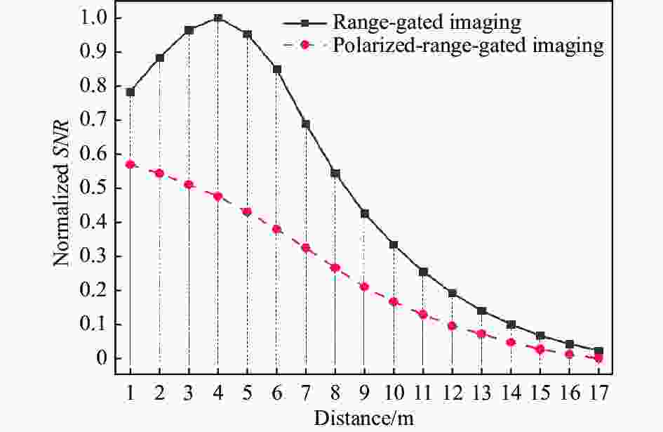
图 2 水体衰减系数0.21 m−1时识别距离和信噪比关系归一化仿真结果
Figure 2. Normalized simulation results between recognition distance and SNR under the water attenuation coefficient of 0.21 m−1
图3为水体衰减系数0.42 m−1时选通成像与偏振选通成像的识别距离和SNR关系归一化仿真结果。如图3所示,偏振选通成像的识别距离约为8 m,选通成像识别距离约为9 m。在该衰减系数下偏振选通成像依然小于选通成像的识别距离,但两者之间差距缩小。根据前述仿真模型可知,当水体衰减系数增加时,水体后向散射增加,水体的散射作用会降低目标识别距离。

图 3 水体衰减系数0.42 m−1时识别距离和信噪比关系归一化仿真结果
Figure 3. Normalized simulation results between recognition distance and SNR under the water attenuation coefficient of 0.42 m−1
图4为水体衰减系数0.63 m−1时选通成像与偏振选通成像的识别距离和SNR关系归一化仿真结果。如图4所示,偏振选通成像的识别距离在5.5~6 m之间,选通成像识别距离在5~5.5 m之间。根据前述仿真模型可知,当水体衰减系数相对较高时,水体后向散射影响严重,相比选通成像,偏振选通成像可提升识别距离。
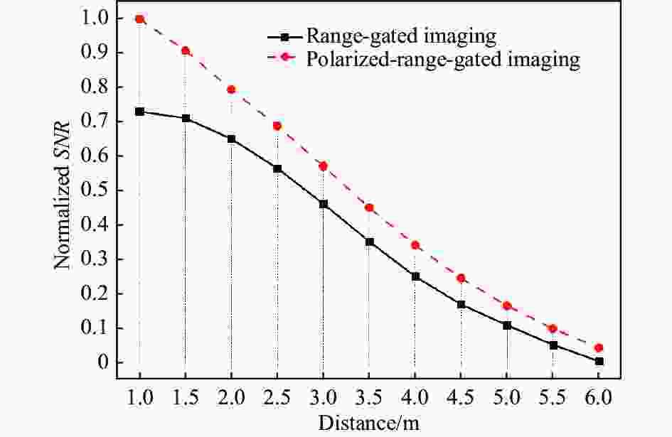
图 4 水体衰减系数0.63 m−1时识别距离和信噪比关系归一化仿真结果
Figure 4. Normalized simulation results between recognition distance and SNR under the water attenuation coefficient of 0.63 m−1
综上,当水体的衰减系数较低时,偏振选通成像难以提升目标识别距离,主要原因是引入偏振后起偏器和检偏器对光能量的衰减作用远大于对后向散射抑制带来的有益效果;当水体衰减系数较大,偏振选通成像可有效抑制后向散射,有效提升目标识别距离。
对比公式(5)和公式(6),由于偏振器的衰减作用,偏振选通成像在过滤后向散射光的同时放大了器件噪声Ed,若将Ed视为定量,可得出如下结论:
1)在低衰减系数水体中,偏振选通成像无法有效提升选通成像的目标识别距离;
2)在高衰减系数水体中,偏振选通成像可有效提升选通成像的目标识别距离。
由上述结果可发现,应存在临界衰减系数c0。当水体衰减系数为c0时,选通成像的识别距离与偏振选通成像的识别距离相当,后续水池实验将进一步验证上述结论。
-
实验装置和实验目标如图5所示。选通成像系统为中国科学院半导体研究所研制的水下距离选通成像系统“凤眼3”,该系统采用532 nm固体半导体激光器作为照明光源,高性能自研ICMOS作为图像采集模块;偏振选通成像系统是在“凤眼3”的基础上增加起偏器和检偏器,其中,起偏器与检偏器依靠支架固定在“凤眼3”系统上。实验目标选用海洋中典型目标渔网和珊瑚,水体衰减系数测量设备为水体衰减系数测量仪C-Star。为模拟深海无光环境,实验在夜间进行。

图 5 实验系统与实验目标
Figure 5. Experimental systems and experimental targets
实验场景图如图6所示,衰减仪与后向散射仪分别用于测量水体的衰减系数与后向散射系数。实验过程中从5 m开始对目标进行成像实验,在低衰减系数下以1 m或2 m为间隔增加目标距离,在高衰减系数下以0.5 m为间隔增加目标距离,直至人眼无法清晰识别成像结果。实验通过添加牛奶调制水体衰减系数,并每隔30 min监测水体参数变化量,以保证实验过程中水体衰减系数的一致性。针对不同水体进行选通成像和偏振选通成像,保证两者视场相同且目标处于相同激光照射下,由于环境因素造成细微的位置偏差对最终结果影响不大。利用算法对不同距离下选通成像和偏振选通成像信噪比进行计算,绘制归一化SNR曲线,验证两者成像效果差异。在绘制过程中,将SNR=2.5作为图像识别最低标准[19],此时对应的成像距离即为最远识别距离。

图 6 实验场景图
Figure 6. Experiment scene diagram
-
图7给出了0.21 m−1衰减系数下渔网成像实验结果,实验中选通参数ICMOS门宽和激光脉宽均为10 ns。图7(a)为渔网识别距离与信噪比归一化曲线实验结果;图7(b)为16 m处渔网选通成像结果,图7(c)为16 m处渔网偏振选通成像结果。由图7(a)可知,选通成像渔网最大识别距离在16~17 m之间,偏振选通成像的渔网最大识别距离在15~16 m之间,偏振选通成像小于选通成像的最大识别距离;如图7(b)和图7(c)所示,16 m处偏振选通成像的图像信噪比差于选通成像。

图 7 衰减系数0.21 m−1下渔网成像实验结果
Figure 7. Experimental results of fishing net under 0.21 m−1 attenuation coefficient
图8给出了0.42 m−1衰减系数下渔网成像实验结果。图8(a)为渔网识别距离与信噪比归一化曲线实验结果;图8(b)为9 m处渔网选通成像结果;图8(c)为9 m处渔网偏振选通成像结果。由图8(a)可知,选通成像渔网最大识别距离在9~10 m之间,偏振选通成像的渔网最大识别距离在8~9 m之间,偏振选通成像小于选通成像的最大识别距离;如图8(b)和图8(c)所示,9 m处偏振选通图像信噪比差于选通成像。

图 8 衰减系数0.42 m−1下渔网成像实验结果
Figure 8. Experimental results of fishing net under 0.42 m−1 attenuation coefficient
图9给出了0.63 m−1衰减系数下渔网成像实验结果。图9(a)为渔网识别距离与信噪比归一化曲线实验结果;图9(b)为5.5 m处渔网选通成像结果;图9(c)为5.5 m 处渔网偏振选通成像结果。由图9(a)可知,选通成像渔网最大识别距离小于5 m,偏振选通成像渔网最大识别距离在5.5~6 m之间,偏振选通成像大于选通成像最大识别距离;如图9(b)和图9(c)所示,5.5 m处偏振选通图像信噪比优于选通成像。

图 9 衰减系数0.63 m−1下渔网实验结果
Figure 9. Experimental results of fishing net under 0.63 m−1 attenuation coefficient
综合三组渔网对照实验可知,在0.42~0.63 m−1之间应存在一临界衰减系数c01。当水体衰减系数大于c01时,渔网偏振选通成像最大识别距离大于选通成像。
-
图10给出了0.21 m−1衰减系数下珊瑚成像实验结果。图10(a)为珊瑚识别距离与信噪比归一化曲线实验结果;图10(b)为19 m处珊瑚选通成像结果;图10(c)为19 m处珊瑚偏振选通成像结果。由图10(a)可知,选通成像珊瑚最大识别距离大于19 m,偏振选通成像珊瑚最大识别距离在15~17 m之间,选通成像大于偏振选通成像的最大识别距离;如图10(b)和图10(c)所示,19 m 处偏振选通成像器件噪声严重,图像信噪比差于选通成像。

图 10 衰减系数0.21 m−1下珊瑚实验结果
Figure 10. Experimental results of coral under 0.21 m−1 attenuation coefficient
图11给出了0.54 m−1衰减系数下珊瑚成像实验结果。图11(a)为珊瑚识别距离与信噪比归一化曲线实验结果;图11(b)为9.5 m处珊瑚选通成像结果;图11(c)为9.5 m处珊瑚偏振选通成像结果。由图11(a)可知,选通成像珊瑚最大识别距离在9~10 m之间,偏振选通成像珊瑚最大识别距离在8~9 m之间,两者识别距离差距缩小;如图11(b)和11(c)所示,9.5 m处偏振选通图像略差于选通成像。

图 11 衰减系数0.54 m−1下珊瑚实验结果
Figure 11. Experimental results of coral under 0.54 m−1 attenuation coefficient
图12给出了0.89 m−1衰减系数下珊瑚实验结果。图12(a)为珊瑚识别距离与信噪比归一化关系实验结果;图12(b)为5 m处珊瑚选通成像结果;图12(c)为5 m处珊瑚选通成像结果。由图12(a)可知,选通成像珊瑚最大识别距离小于5 m,偏振选通成像珊瑚最大识别距离约为5.5 m,偏振选通成像识别距离大于选通成像;如图12(b)和12(c)所示,5 m处偏振选通图像信噪比优于选通成像。

图 12 衰减系数0.89 m−1下珊瑚实验结果
Figure 12. Experimental results of coral under 0.89 m−1 attenuation coefficient
综合三组珊瑚对照实验可知:在0.54~0.89 m−1之间存在临界衰减系数c02。当水体衰减系数大于c02时,偏振选通成像珊瑚最大识别距离大于选通成像。
-
综合理论仿真与实验结果,可得出如下结论:
1)存在临界衰减系数c0,该系数决定选通成像和偏振选通成像的适用水质。
当水质较好、水体衰减系数小于c0时,选通成像的作用距离远于偏振选通成像,偏振引起的能量损失负面问题强于后向散射抑制带来的有益效果,即弊大于利,从而对于提升选通成像无效果;当在c0水质时,选通成像和偏振选通成像的作用距离相当,偏振引起的能量损失负面问题与后向散射抑制带来的有益效果相抵消,即利弊相抵,偏振对于提升选通成像的作用距离无明显效果;当水质较差、水体衰减系数大于c0时,偏振选通成像的作用距离远于选通成像,偏振抑制后向散射带来的有益效果强于偏振引起的能量损失负面问题,即利大于弊,从而提升了选通成像的作用距离。
2)临界衰减系数c0与目标反射率有关。
从渔网和珊瑚等典型海洋目标实验结果可以发现,两者的临界衰减系数不同。主要原因是渔网和珊瑚的反射率不同,目标反射率会影响到图像的信噪比,从而影响目标识别距离。因此,使用偏振提升不同水下目标选通成像作用距离时,临界衰减系数也不同。
-
针对浑浊水体中选通成像质量受切片内残留后向散射噪声影响的问题,文中将光学偏振成像与选通成像结合,利用目标反射光和水体后向散射光之间的偏振度差异来过滤后向散射噪声,提升选通成像的作用距离和信噪比。通过理论仿真和水池实验对比分析了不同水质下选通成像和偏振选通成像目标识别距离的差异,并发现存在临界衰减系数。在水质较清时(小于等于临界衰减系数),单纯采用选通成像即可,效果最佳;在水质浑浊时(不小于临界衰减系数),偏振与选通成像结合,可提升作用距离。该研究结果有益于不同水质下合理应用选通成像,特别是浑浊水体下,利用光学偏振可以进一步提升选通成像的工作距离。
Influence of optical polarization on underwater range-gated imaging for target recognition distance under different water quality conditions
-
摘要: 水下光学成像技术对于海底资源勘测、海洋生态监测、水下搜索救援、水下考古等应用具有重要意义。相比传统水下摄像机,距离选通成像技术可以过滤选通切片外的后向散射噪声和环境背景噪声,实现高质量水下成像,但是在浑浊水体中仍然会受切片内后向散射噪声影响,导致成像距离缩短。对此,开展了光学偏振与距离选通成像结合的水下偏振选通成像技术研究,利用后向散射光良好的保偏性去除选通切片范围内的后向散射噪声,提升目标识别距离。通过理论仿真和实验研究,对比分析了不同水质下距离选通成像和偏振选通成像目标识别距离的差异。发现存在临界衰减系数c0:当水体衰减系数小于等于c0时,光学偏振对于提升距离选通成像工作距离无效果;当水体衰减系数大于c0时,偏振可提升距离选通成像工作距离。实验中还发现,目标反射率会影响临界衰减系数。该研究有利于不同水质下距离选通成像的优化应用。Abstract:
Objective Underwater optical imaging technology is of great significance for applications such as seabed resource exploration, marine ecological monitoring, underwater search and rescue, and underwater archaeology. Compared to traditional underwater cameras, underwater range-gated imaging (RGI) technology can filter out backscattered noise and environmental background noise outside the gated slice, achieving high-quality underwater imaging. However, in turbid water bodies, it is still affected by backscattered noise inside the slice, resulting in a shorter imaging distance. Methods In view of the problem of short RGI distance in highly turbid water bodies, underwater polarization gating imaging technology combining optical polarization and RGI was studied. By utilizing the good polarization preservation of backscattered light, the backscattered noise within the gating slice range was removed, and the target recognition distance was improved (Fig.1). Firstly, a physical model for polarized-range-gated imaging (PRGI) is established, a formula for calculating the signal-to-noise ratio of PRGI is derived, a normalized simulation curve for signal-to-noise ratio is drawn. Subsequently, RGI and PRGI are performed on underwater targets such as fishing nets and corals, and signal-to-noise ratio normalization experimental curves are drawn. The simulation curves and experimental curves are compared and analyzed. Results and Discussions When the water attenuation coefficient is 0.21 m−1, the PRGI recognition distance is about 15 m, and the RGI recognition distance is about 17 m (Fig.2). The reason why the recognition distance of PRGI is smaller than RGI is that under the low water attenuation coefficient, the backscattering of the water body is small, and the absorption effect of the water body plays a major role in limiting the recognition distance. When the water attenuation coefficient is 0.42 m−1, the recognition distance of PRGI is about 8 m, and RGI recognition distance is about 9 m (Fig.3). The gap between the two has narrowed. The reason is that as water attenuation coefficient increases, the backscattering of water increases, and the scattering effect of water will reduce the target recognition distance. When the water attenuation coefficient is 0.63 m−1, the recognition distance of PRGI is between 5.5 m and 6 m, and the recognition distance of RGI is between 5 m and 5.5 m (Fig.4). When the water attenuation coefficient is relatively high, the backscattering effect of water is severe, PRGI can improve the recognition distance compared with RGI. The experimental results of fishing net imaging under the water attenuation coefficient of 0.21 m−1 show that the signal-to-noise ratio of PRGI at 16 m is lower than RGI (Fig.7). The experimental results of fishing net imaging under the water attenuation coefficient of 0.42 m−1 show that the signal-to-noise ratio of PRGI at 9 m is lower than RGI (Fig.8). The experimental results of fishing net imaging under the water attenuation coefficient of 0.63 m−1 show that the signal-to-noise ratio of PRGI at 5.5 m is better than RGI (Fig.9). The experimental results of coral imaging under the water attenuation coefficient of 0.21 m−1 show that PRGI have severe device noise at 19 m, and the signal-to-noise ratio of the image is worse than RGI (Fig.10). The experimental results of coral imaging under the water attenuation coefficient of 0.54 m−1 show that PRGI at 9.5 m is slightly worse than RGI (Fig.11). The coral experiment results under the water attenuation coefficient of 0.89 m−1 show that the signal-to-noise ratio of PRGI at 5 m is better than RGI (Fig.12). Conclusions According to the comparison experiment between fishing nets and coral, there should be a critical attenuation coefficient c01 between 0.42 m−1 and 0.63 m−1. When the water attenuation coefficient is higher than c01, the maximum recognition distance of PRGI of fishing nets is greater than RGI; There is a critical attenuation coefficient c02 between 0.54 m−1 and 0.89 m−1. When the water attenuation coefficient is higher than c02, the maximum recognition distance of PRGI of coral is greater than RGI. Based on the comprehensive simulation and experimental results, the following conclusions can be drawn. 1) There exist a critical attenuation coefficient c0, which determines the applicable water quality for RGI and PRGI. 2) The critical attenuation coefficient c0 is related to the target reflectivity. -
图 2 水体衰减系数0.21 m−1时识别距离和信噪比关系归一化仿真结果
Figure 2. Normalized simulation results between recognition distance and SNR under the water attenuation coefficient of 0.21 m−1
图 3 水体衰减系数0.42 m−1时识别距离和信噪比关系归一化仿真结果
Figure 3. Normalized simulation results between recognition distance and SNR under the water attenuation coefficient of 0.42 m−1
图 4 水体衰减系数0.63 m−1时识别距离和信噪比关系归一化仿真结果
Figure 4. Normalized simulation results between recognition distance and SNR under the water attenuation coefficient of 0.63 m−1
图 7 衰减系数0.21 m−1下渔网成像实验结果
Figure 7. Experimental results of fishing net under 0.21 m−1 attenuation coefficient
图 8 衰减系数0.42 m−1下渔网成像实验结果
Figure 8. Experimental results of fishing net under 0.42 m−1 attenuation coefficient
图 9 衰减系数0.63 m−1下渔网实验结果
Figure 9. Experimental results of fishing net under 0.63 m−1 attenuation coefficient
图 10 衰减系数0.21 m−1下珊瑚实验结果
Figure 10. Experimental results of coral under 0.21 m−1 attenuation coefficient
图 11 衰减系数0.54 m−1下珊瑚实验结果
Figure 11. Experimental results of coral under 0.54 m−1 attenuation coefficient
-
[1] Deng X, Wang H, Liu X, et al. State of the art of the underwater image processing methods [C]//2017 IEEE International Conference on Signal Processing, Communications and Computing (ICSPCC). IEEE, 2018: 8242429. [2] 曹峰梅, 金伟其, 黄有为等. 水下光电成像技术与装备研究进展(上)—— 水下激光距离选通技术[J]. 红外与激光工程, 2011, 33. (2): 1001-8891. Cao Fengmei, Jin Weiqi, Huang Youwei, et al. Review of underwater opto-electrical imaging technology and equipment (I) —— Underwater laser range-gated imaging technology [J]. Infrared and Laser Engineering, 2011, 33(2): 1001-8891. (in Chinese) [3] Philip Church, Weilin Hou, Georges Fournier, et al. Overview of a hybrid underwater camera system [C]//Proceedings of SPIE, 2014, 9111: 911100. [4] 王新伟, 孙亮, 王敏敏, 杨于清, 周燕. 水下二维及三维距离选通成像去噪技术研究[J]. 红外与激光工程, 2020, 49(2): 0203002. Wang Xinwei, Sun Liang, Wang Minmin, et al. Deblurring methods for underwater 2D and 3D range gatedimaging [J]. Infrared and Laser Engineering, 2020, 49(2): 003002. (in Chinese) [5] Wang M, Wang X, Zhang Y, et al. Range-intensity-profile prior dehazing method for underwater range-gated imaging [J]. Optics Express, 2021, 29(5): 7630-7640. doi: 10.1364/OE.417131 [6] Hu Haofeng, Li Xiaobo, Liu Tiegen. Recent advances in underwater image restoration technique based on polarimetric imaging [J]. Infrared and Laser Engineering, 2019, 48(6): 0603006. (in Chinese) [7] Treibitz T, Schechner Y Y. Active polarization descattering [J]. IEEE Transactions on Pattern Analysis and Machine Intelligence, 2009, 31(3): 385-399. doi: 10.1109/TPAMI.2008.85 [8] Cheng Q, Wang Y, Li D. Analysis of polarization characteristics of backscattered light and reflected light of underwater active light source [J]. Optical Engineering, 2021, 60: 126105. [9] 秦琳, 陈名松, 阙斐一. 基于距离选通的水下偏振光成像系统的研究[J]. 电子设计工程, 2011, 19(07): 184-186. DOI: 10.14022/j.cnki.dzsjgc.2011.07.001. Qin Lin, Chen Mingsong, Que Feiyi. Investigation of underwater polarization imagine system based on range-gated techniques [J]. Electronic Design Engineering, 2011, 19(7): 184-186. (in Chinese) doi: 10.14022/j.cnki.dzsjgc.2011.07.001 [10] Wang Xinwei, Sun Liang, Liu Yuliang. Impact of echo broadening effect on active range-gated imaging [J]. Chinese Optics Letters, 2012, 10(10): 101101. doi: 10.3788/COL201210.101101 [11] Ge Weilong, Hua Lianghong, Zhang Xiaohui. Signal to noise research in range-gated underwater laser imaging system [J]. Infrared and Laser Engineering, 2013, 42(8): 2022-2026. (in Chinese) [12] 李丽, 高稚允, 王霞等. 水下距离选通成像系统后向散射光的计算[J]. 北京理工大学学报, 2003, 23(4): 4882491. doi: 10.15918/j.tbit1001-0645.2003.04.022 Li Li, Gao Zhiyun, Wang Xia, et al. Optical backscatter calculation for an underwater range-gated imaging system [J]. Transactions of Beijing Institute of Technology, 2003, 23(4): 4882491. (in Chinese) doi: 10.15918/j.tbit1001-0645.2003.04.022 [13] Maffione R A, Spinrad R W, Dana D R, et al. Instrument for underwater measurement of optical backscatter [C]//Proceedings of SPIE, 1991, 1537: 173-184. [14] Liu Quanhua, Weng Fuzhong. Combined Henyey-Greenstein and Rayleigh phase function [J]. Applied Optics, 2006, 45(28): 7475-7479. doi: 10.1364/AO.45.007475 [15] Cornette W M, Shanks J G. Physically reasonable analytic expression for the single-scattering phase function [J]. Applied Optics, 1992, 31(16): 3152-3160. doi: 10.1364/AO.31.003152 [16] Morgan S P, Ridgway M E. Polarization properties of light backscattered from a two layer scattering medium [J]. Optics Express, 2000, 7(12): 395-402. doi: 10.1364/OE.7.000395 [17] 曹先平, 孙萍, 不同波长的散射介质后向散射光偏振度特性[J]. 光子学报 , 2012 , 41(5): 0506-086. Cao Xianping, Sun Ping. Characteristics of degree of polarization of backscattering light in scattering medium at different wavelengths [J]. Acta Photonica Sinica, 2012, 41(5): 608-613. (in Chinese) [18] 石顺祥, 王学恩, 马琳. 物理光学与应用光学 [M]. 西安: 西安电子科技大学出版社, 2014. [19] 白廷柱, 金伟其. 光电成像原理与技术 [M]. 北京: 北京理工大学出版社, 2006. -

 点击查看大图

计量
- 文章访问数: 125
- HTML全文浏览量: 30
- PDF下载量: 36
- 被引次数: 0

