


 下载:
下载:

-
机载光电平台作为一种工作在复杂航空环境下的光电设备,其精度是由光、机、电三者误差相互耦合传递决定,如果在安装时采用刚性联接方式,外界的各种扰动势必会耦合到平台上,造成载荷像质及整体功能退化[1-2],而采用减振技术后,一方面经减振器可有效隔离发动机等产生的高频振动,能够降低伺服控制系统的带宽要求和光电平台视轴稳定难度,另一方面,利于光电平台获得更为清晰的视频或静态图像[3-4]。
国内外学者针对减振器进行过深入的研究[5-6]。近年来,各类减振器补偿技术[7-8]及各式减振器被广泛地应用于航空航天等诸多领域[9-11]。由于航空光电平台角位移对平台性能的影响明显大于线位移,因此,很多工作围绕无角位移减振器展开。实际上,体积大、质量重的无角位移减振器在承载能力有限的无人机上工程化意义不大。王家琪等人研究了影响无人机载光电平台设备性能的因素[12],杜言鲁[13] 、赵奎[14]等人针对无人机载光电平台深入研究了其振动特点,但很多工作停留在理论层面,未能定量分析解决振动对光电平台带来的影响及使用阻尼减振器后如何优化光电平台的安装布局。
文中通过分析当前光电平台阻尼减振器的特性,建立了安装阻尼减振器后的平台减振系统运动模型,结合阻尼减振器安装形式进一步建立了光电平台的角位移模型,给出了使用阻尼减振器后平台隔振性能的影响因素,并实验条件下以某型光电平台及阻尼减振器为例进行了系统性测试验证。结果表明:论文对光电平台的设计优化及性能测试能够提供良好的技术支撑和理论基础。
-
阻尼减振器的核心部件是内部弹簧,弹簧阻尼系数不同时其减振特性不同。当存在外部扰动时,外力引起的振动会被弹簧弹性形变吸收,从而达到隔振的目的。为了衡量隔振效果的优劣,定义传递力与原振动力的百分比为振动传递率T,且当振动传递率T<1时才有减振的效果。
振动传递率T对于弹簧或者橡胶等粘性阻尼系统的一般表达形式为:
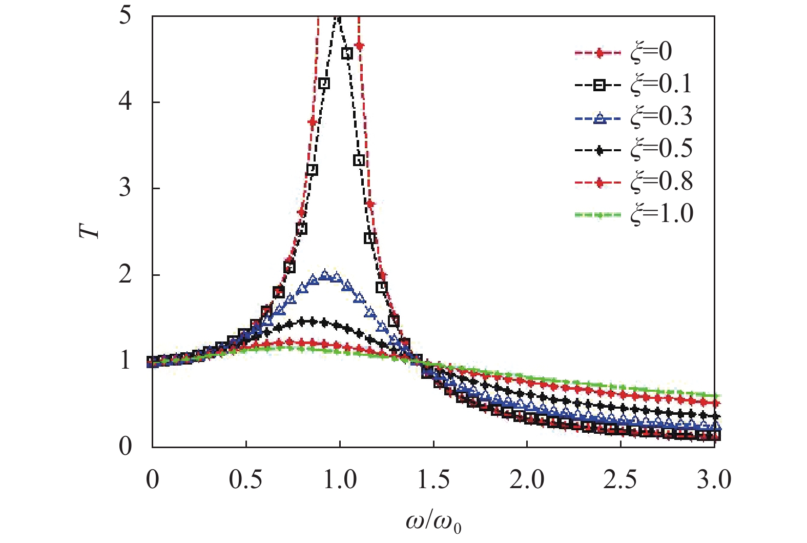
$$ {{T}} = \sqrt {\frac{{1 + 4{\xi ^2}{{({{\omega}} /{{{\omega}} _0})}^2}}}{{{{[1 - {{({{\omega}} /{{{\omega}} _0})}^2}]}^2} + 4{\xi ^2}{{({{\omega}} /{{{\omega}} _0})}^2}}}} $$ (1) 式中:ω为激励频率;ω0为系统固有频率;ξ为系统阻尼比。这三者之间的关系如图1所示。不难发现,当ω/ω0=1时,此时T达到了最大,称为共振状态,在工程隔振设计中要尽量避免;当ω/ω0<1.414时,振动传递率T=1,此时无隔振效果,相当于系统刚性相接;当ω/ω0>1.414时,振动传递率T<1,设计具有隔振效果,振动传递率T由公式(1)给出。因此,一个合理的隔振系统设计时应当满足振动传递率T <1且ω/ω0>1.414。实际工程设计时,需兼顾隔振效果和设计难度,通常ω/ω0取2.5~4.5之间。

图 1 减振器传递率与频率比关系图
Figure 1. Relationship between damper transmissibility and frequency
-
当载机姿态及飞行速度变化、外部气流扰动等各种飞行不确定因素干扰时,阻尼减振器的介入将不可避免地引起载机与光电平台间相对位移变化[15]。根据阻尼减振器的特性,此位移包含相对角位移与线位移。由于航空光电平台相对角位移对平台性能的影响要比线位移明显得多,因此,论文将结合某型光电平台安装阻尼减振器后的运动特性,建立其角位移模型。由于平台与载机间发生相对角位移时,其旋转中心并不固定,因此,建立任意点为旋转中心的光电平台角位移模型更具有意义。建立的相对角位移模型如图2所示。

图 2 任意旋转中心O的旋转角度与位移间的关系
Figure 2. Relationship between displacement and angle across rotating center O
假设O为任意点旋转中心,P1、P2为光电平台旋转时沿其转角最大方向上间距最远两点距离,θ为平台相对角位移大小,r与δ分别表示端点P2的纵向与横向位移大小。当任意旋转发生时,P1、P2分别以旋转半径R1、R2转动,且P1、P2旋转至P1′、P2′处。由几何知识可知,其纵向位移r与横向位移δ分别满足:
$$ {{r}} = {{{R}}_1}\sin \theta $$ (2) $$ {{\delta}} = {{r}}\tan \frac{\theta }{2} = {{{R}}_1}\sin \theta \tan \frac{\theta }{2} $$ (3) 由于阻尼减振器限位的存在,假定M为减振器最大移动上限,则r≤2L mm。显然各种条件限制下,
$$ \left\{ {\begin{array}{*{20}{c}} {0 \leqslant {{l}} + {{r}} \leqslant 2{{M}},\;0 \leqslant {{l}} \leqslant 2{{M}},\;0 \leqslant {{r}} \leqslant 2{{M}}} \\ {\sin \theta = {{r}}/{{{R}}_1},\;\sin \theta = {{l}}/{{{R}}_2},\;{{{R}}_1} + {{{R}}_2} = 2{{R}}} \end{array}} \right. $$ (4) 公式(4)中,θ的最大值发生在R1=R2=R处,即光电平台以安装平面正中心旋转时,其转角达到最大值。转角θ由公式(5)决定:
$$ \theta = \arcsin (2{{r}}/{{R}}) $$ (5) -
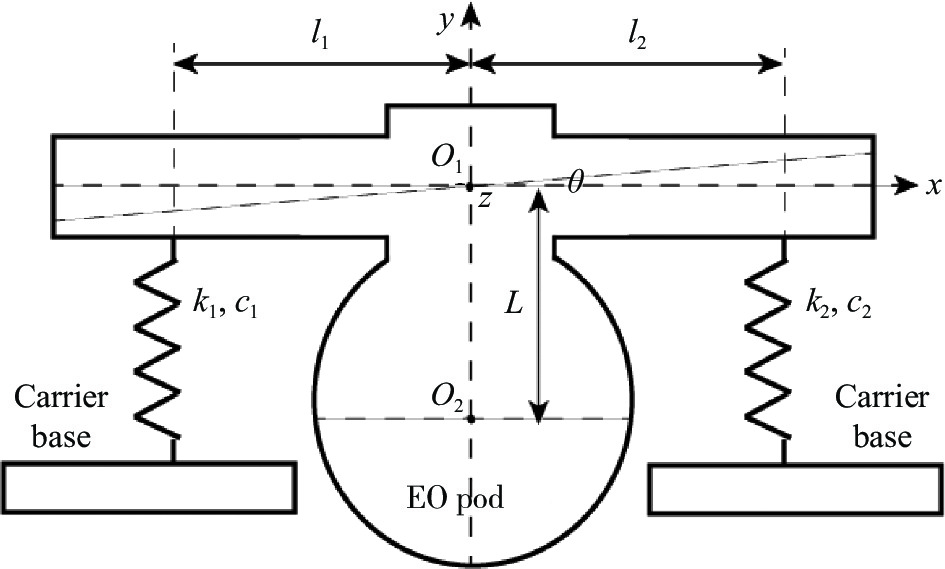
目前,光电平台采用四个顶角定点安装阻尼减振器的方式与载机挂接,同时,安装的过程中尽可能保证平台的质心通过四个减振器所在平面的中垂线上,一方面可使减振效果最为理想,另一方面可避免出现个别减振器过度受力的现象。假设平台以安装平面中心O1为旋转中心发生最大角位移,建立的系统运动模型直角坐标系统O1xyz如图3所示。坐标原点位于平台的安装平面中心O1,x轴水平向右,y轴竖直向上,z轴与x、y轴形成右手坐标系统。光电平台质心为O2,k1与k2为阻尼减振器刚度,c1与c2为阻尼减振器阻尼系数,l1与l2为减振器距原点的距离,L为平台质心距坐标系原点O1的距离,θ为光电平台与载机基座间的相对角位移。

图 3 光电平台阻尼减振器运动模型图
Figure 3. Motion model of damping damper in EO pod
则安装阻尼减振器后的光电平台运动学方程可表示为:
$$ \begin{split} & {{m}}\ddot {{x}} + \left( {{{{c}}_1} + {{{c}}_2}} \right)\dot {{x}} + \left( {{{{c}}_2}{{{l}}_2} - {{{c}}_1}{{{l}}_1}} \right)\dot \theta + \left( {{{{k}}_1} + {{{k}}_2}} \right) \\ & {{x}} + \left( {{{{k}}_2}{{{l}}_2} - {{{k}}_1}{{{l}}_1}} \right)\theta = \left( {{{{c}}_1} + {{{c}}_2}} \right){{\dot {{x}}}_i} + \left( {{{{k}}_1} + {{{k}}_2}} \right){{{x}}_i} \\ \end{split} $$ (6) $$ \begin{split} &{{{I}}_0}\ddot \theta + \left( {{{{c}}_2}{{{l}}_2} - {{{c}}_1}{{{l}}_1}} \right)\dot {{x}} + \left( {{{{c}}_2}{{l}}_2^2 + {{{c}}_1}{{l}}_1^2} \right)\dot \theta + \\ &\left( {{{{k}}_2}{{{l}}_2} - {{{k}}_1}{{{l}}_1}} \right){{x}} + \left( {{{{k}}_1}{{l}}_1^2 + {{{k}}_2}{{l}}_2^2} \right)\theta = \\ & \left( {{{{c}}_2}{{{l}}_2} - {{{c}}_1}{l_1}} \right){{\dot {{x}}}_i} + \left( {{{{k}}_2}{{{l}}_2} - {{{k}}_1}{{{l}}_1}} \right){{{x}}_i} + {{m}}\ddot {{y}}{{L}} \\ \end{split} $$ (7) 将所有的初始条件均设置为0时,将上述光电平台运动学方程进行拉普拉斯变换,整理后得到:
$$ \begin{split} &\left[ {{{{ms}}^2} + \left( {{{{c}_1}} + {{{c}_2}}} \right){{s}} + \left( {{{{k}_1}} + {{{k}}_2}} \right)} \right]{{X}}({{s}}) + \\ &\left[ {\left( {{{{c}_2}}{{l}_2} - {{{c}_1}}{{l}_1}} \right){{s}} + \left( {{{{k}_2}}{{l}_2} - {{{k}_1}}{{l}_1}} \right)} \right]\theta ({{s}}) = \\ &\left[ {\left( {{{{c}_1}} + {{{c}_2}}} \right){{s}} + \left( {{{{k}_1}} + {{{k}_2}}} \right)} \right]{{{X}}_i}({{s}}) \\ \end{split} $$ (8) $$ \begin{split} &\left[ {\left( {{{c}_2}{{l}_2} - {{c}_1}{{l}_1}} \right){{s}} + \left( {{{k}_2}{{l}_2} - {{k}_1}{{l}_1}} \right)} \right]{{X}}({{s}}) + \\ & \left[ {{{I}_0}{{{s}}^2} + \left( {{{k}_1}l_1^2 + {{k}_2}{{l}_2}^2} \right) + \left( {{{c}_1}{{l}}_1^2 + {{c}_2}{{l}_2}^2} \right){{s}}} \right] \\ & \theta ({{s}}) = \left[ {\left( {{{c}_2}{{l}_2} - {{c}_1}{{l}_1}} \right){{s}} + \left( {{{k}_2}{{l}_2} - {{k}_1}{{l}_1}} \right)} \right] \\ & {{{X}}_i}({{i}}) + {{mY}}({{s}}){{L}}{{{s}}^2} \\ \end{split}$$ (9) 结合公式(8)、(9)与振动传递率Ta的定义,即可得到x与y方向上振动传递率Tax与Tay分别表示为:
$$ {{{T}}_{ax}} = \frac{{{{{ms}}^3}\left( {{{{c}}_2}{{{l}}_2} - {{{c}}_1}{{{l}}_1}} \right) + {{{ms}}^2}\left( {{{{k}}_2}{{{l}}_2} - {{{k}}_1}{{{l}}_1}} \right)}}{{{S}}} $$ (10) $$ {{{T}}_{ay}} = \frac{{{{{Ls}}^2}\left[ {{{{ms}}^2} + \left( {{{{c}}_1} + {{{c}}_2}} \right){{s}} + \left( {{{{k}}_1} + {{{k}}_2}} \right)} \right]}}{{{S}}} $$ (11) 上述公式(10)、(11)中,S代表扰动引起的原振动力,其表达式为:
$$ \begin{gathered} {{S}} = {{{mI}}_0}{{{s}}^4} + \left[ {({{{c}}_1} + {{{c}}_2}){{{I}}_0} + {{m}}({{{c}}_1}{{l}}_1^2 + {{{c}}_2}{{l}}_2^2)} \right]{{{s}}^3} + \\ \left[ {{{m}}({{{k}}_1}{{l}}_1^2 + {{{k}}_2}{{l}}_2^2) + ({{{k}}_1} + {{{k}}_2}){{{I}}_0} + {{{c}}_1}{{{c}}_2}{{({{{l}}_1} + {{{l}}_2})}^2}} \right] \cdot \\ {{{s}}^2} + ({{{k}}_1}{{{c}}_2} + {{{k}}_2}{{{c}}_1}){({{{l}}_1} + {{{l}}_2})^2}{{s}} + {{{k}}_1}{{{k}}_2}{({{{l}}_1} + {{{l}}_2})^2} \\ \end{gathered} $$ (12) 显然,如果想让系统在x和y方向上的传递率均为零,须满足k1l1=k2l2,c1l1=c2l2和L=0;此时,光电平台的线振动wl与角振动固有频率wr分别为:
$$ {{{w}}_l} = \sqrt {\frac{{{{{k}}_1} + {{{k}}_2}}}{{{m}}} - \frac{{{{({{{c}}_1} + {{{c}}_2})}^2}}}{{4{{{m}}^2}}}} $$ (13) $$ {{{w}}_r} = \sqrt {\frac{{{{{k}}_1}l_{{1}}^2 + {{{k}}_2}{{l}}_2^2}}{{{{{I}}_0}}} - \frac{{{{({{{c}}_1}{{l}}_{{1}}^2 + {{{c}}_2}{{l}}_2^2)}^2}}}{{4{{I}}_0^2}}} $$ (14) 实际工程应用中,减振器的种类决定其刚度k和阻尼系数c几乎完全一致。因此,当k1=k2=k、c1=c2=c、l1=l2=l并将光电平台近似等效为质量均匀分布的理想球体时,公式(13)、(14)可简化为:
$$ {{{w}}_l} = \sqrt {\frac{{2{{km}} - {{{c}}^2}}}{{{{{m}}^2}}}} $$ (15) $$ {{{w}}_r} = \frac{{5{{k}}}}{{2{{ml}}}}\sqrt {\frac{{4{{k}} - 5{{m}}{{{c}}^2}}}{{5{{m}}}}} $$ (16) 从公式(15)、(16)可以看出,光电平台线振动与阻尼减振器的刚度、阻尼系数及平台自身质量有关,与阻尼减振器安装位置无关;而光电平台角振动与平台质量、阻尼系数、阻尼减振器刚度和阻尼减振器的安装位置均相关。一方面,可以在减振器性能设计上优化平台隔振效果;另外一方面,在选定了阻尼减振器后,可以通过合理布局其安装位置以优化提升光电平台的隔振性能。
-
1)仿真结果
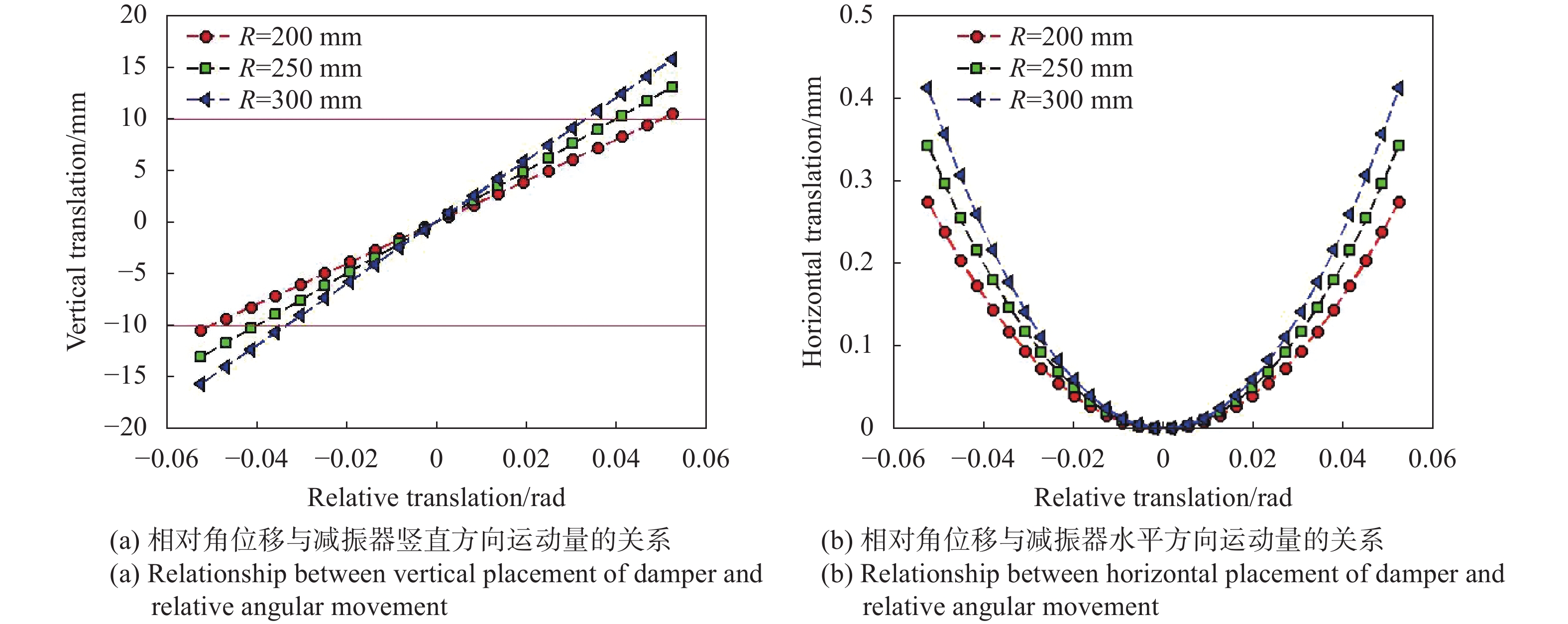
以某型阻尼减振器为例,其竖直方向有效行程为20 mm、水平方向行程为0.4 mm。当光电平台因外部扰动达到阻尼减振器的机械限位时,光电平台与载机间的相对角位移超过0.05 rad (3°),且光电平台受力支撑点运动主要集中于竖直方向上,水平方向上运动量十分微小。假定光电平台安装阻尼减振器后产生角位移的旋转半径R分别为200 mm、250 mm和300 mm,结合公式(8)可得到相对角位移与阻尼减振器在竖直和水平方向上的行程对应关系如图4所示,图中红线部分的区域代表了减振器的有效行程区域,红色直线以外的部分由于其限位存在实际使用时并不可能达到,此时水平方向上线位移仅为竖起方向上的2%。

图 4 光电平台相对角位移与减振器自身运动量的关系
Figure 4. Relationship between placement of damper and relative angular movement of EO pod
2)实验验证
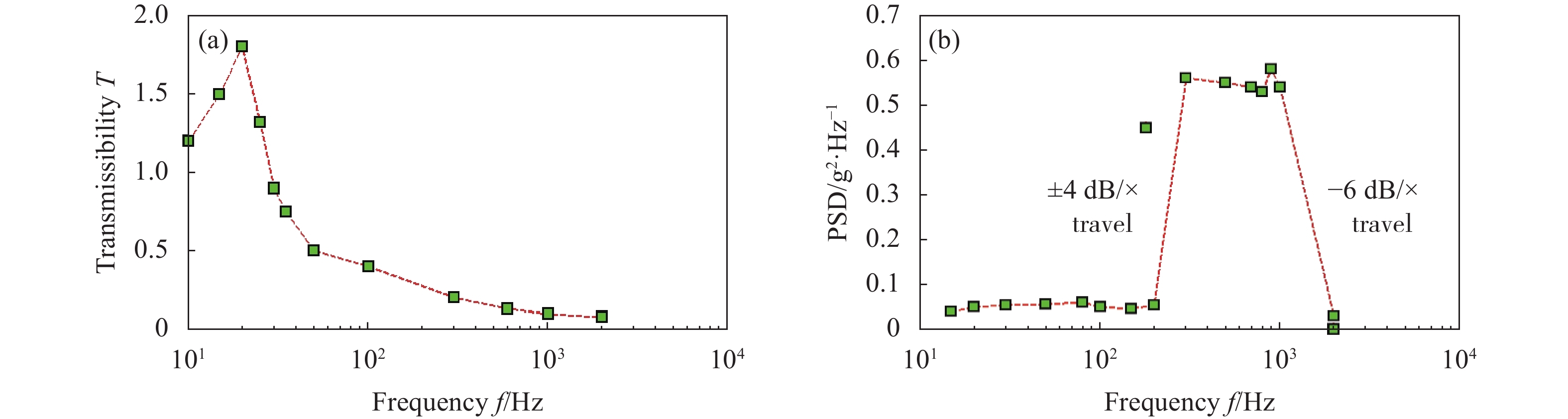
由于机载光电平台使用被动隔振技术,在实验室现有条件下可使用振动台测试某型光电平台阻尼减振器性能,测得振源频率f与传递率T之间减振效果拟合曲线如图5所示。可以看出,在30 Hz以上时其传递率T <1,即减振器对30 Hz以上的扰动隔离效果明显;对于超过50 Hz的扰动其垂向传递率T <0.5,即减振器可以有效隔离如飞机发动机等引起的高频振动,而对低频效果并不明显;相比之下,机载环境下对设备性能影响最为明显的恰是高频振动因素,因此,实际测试证明此类减振器应用于隔离机载环境振动是合理的。
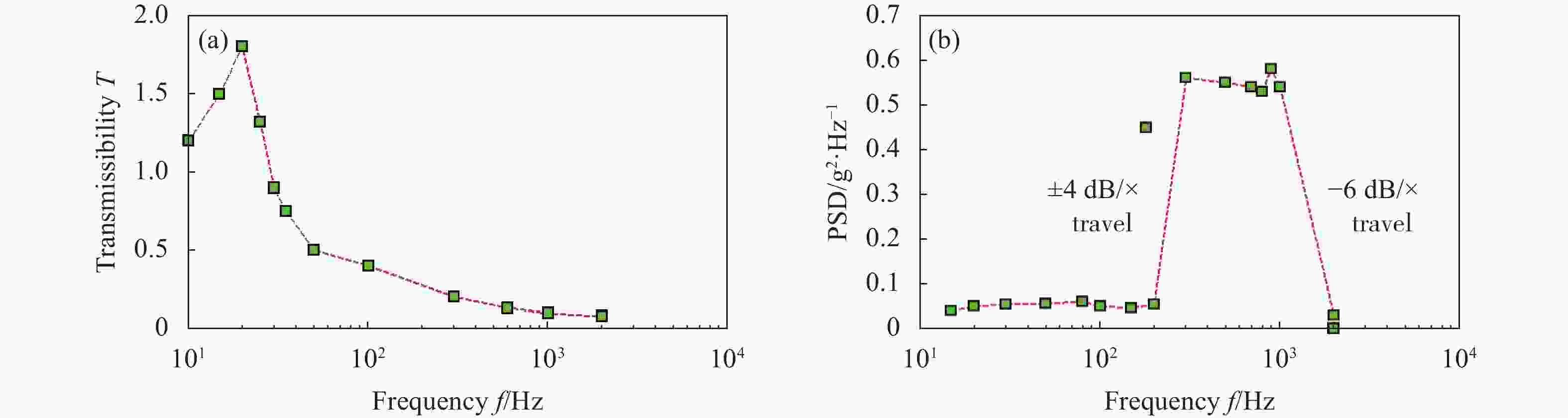
图 5 某型减振器扰动频率与传递率、功率谱密度间的测试结果
Figure 5. Test results of transmissibility and power spectral density on different disturbance frequency of a certain damper
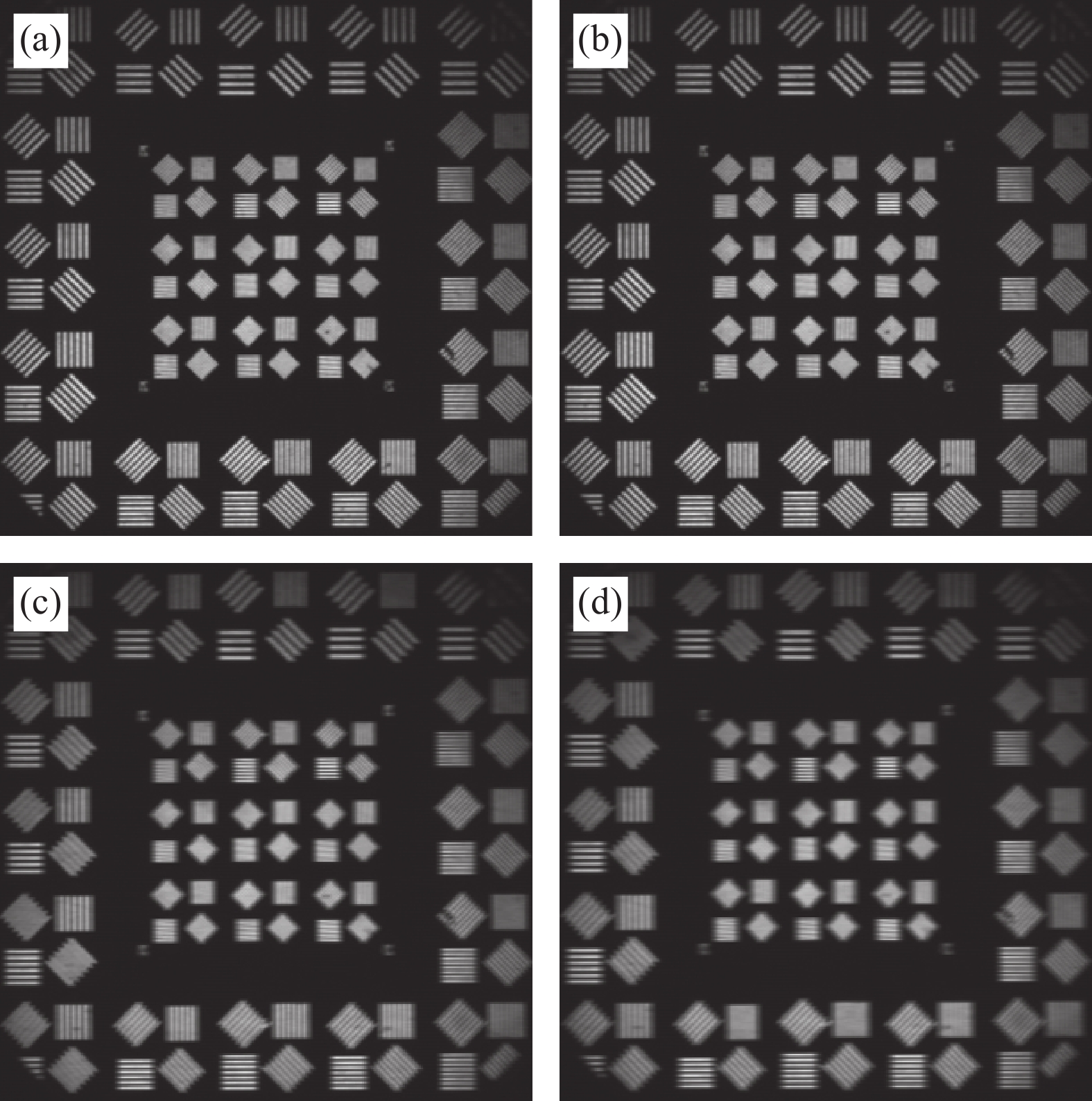
实际工程应用中,同一型号阻尼减振器其刚度k和阻尼系数c几乎相同,因此,文中将深入研究阻尼减振器安装位置不同时角位移时对光电平台成像质量的影响。由于阻尼减振器对低频扰动的隔离效果并不理想,论文考察了在5 Hz的低频扰动下阻尼减振器安装位置对光电平台整体性能的影响。首先,对光电平台持续引入5 Hz的低频扰动,同时,分别将光电平台的四个阻尼减振器安装中心距分别设置为350 mm、300 mm、200 mm和100 mm,并在相同条件下使用光电平台内部载荷观测平行光管靶标,载荷成像如图6(a)~(d)所示。能够看出,在外部扰动一定时,随着光电平台减振器回转中心距的减小,平台内部载荷能够分辨测试靶标的能力逐渐下降,即减振器的安装中心距变化对成像像质影响十分明显。因此,在实际工程中,应尽可能增大光电平台的减振器安装中心距以提高整体隔振及载荷成像效果。

图 6 光电平台外部扰动相同时,350 mm (a)、300 mm (b)、200 mm (c)和100 mm (d)安装中心距时成像对比
Figure 6. Imaging contrast of EO pod with 350 mm (a), 300 mm (b), 200 mm (c) and 100 mm (d) deviating from mounting center on the same disturbance
-
文中对无人机载光电平台和相关阻尼减振器特性、运动建模及测试应用进行了深入研究。在介绍阻尼减振器及光电平台工作原理的基础上,建立了安装阻尼减振器后的机载光电平台相关运动特性模型;同时,不仅对理论模型进行了仿真,并在实验室条件下给出了实际测试结果。结果表明:模型基本能够反映阻尼减振器对无人机载光电平台整体性能的影响,研究成果对优化无人机载光电平台设计、安装等实际工程应用具有十分重要的指导作用。
Test and analysis of vibration characters of damper in EO platform of UAV
-
摘要: 针对无人机载光电平台的安装特点,文中对平台及阻尼减振器特性进行了分析、建模与测试。首先,对光电平台阻尼减振器特性进行了介绍;其次,分析了安装阻尼减振器后的光电平台特性,并对阻尼减振器的运动特性进行建模,分析阻尼减振器安装布局与平台性能之间的关系;最后,结合具体某型光电平台及其配套阻尼减振器,给出了仿真结果及相同外部扰动条件下减振器安装位置对平台性能的测试结果。结果表明:相关研究对优化无人机载光电平台阻尼减振器布局及提升载荷整体性能具有积极的意义。Abstract:
Objective Absorber is a very commonly used component in UAV OE platform, because it can effectively absorb the vibration caused by the UAV, thereby enabling the photoelectric platform to obtain more stable and clear image or video. In the recent years, many scholars focus their attention on many kinds of damper in order to further improve the imaging quality of the OE platform. Non-angular displacement damper is designed for optimizing the performance of platform payload, but its practicality is limited by large volume and heavy weight. So traditional damping absorber is still the most widely used damper in OE platform at present. A lot of research have been conducted about the characters of damping absorber, but quantitative analysis to address the impact of vibration on optoelectronic platforms and how to optimize the installation layout of OE platform with damping absorber has not been carried out. Methods According to the characters of airborne OE payload, this paper analyzes and tests the angular characteristics of damping absorber that is related to the performance of airborne payload. First, the self-character of damper of EO payload is introduced. Second, the overall performance model of EO payload are established. Meanwhile, the modeling of motion characteristics is established and the factors that may affect the ability of airborne payload are analyzed during the installation layout of damping absorber. Many factors, such as stiffness, damping coefficient, installment-center-distance and the mass of payload, are promoted which determine the results of angular and linear displacement. Results and Discussions The results of simulation analysis show that the displacement of damper mainly occurs in the vertical direction instead of horizontal direction, and the displacement in horizontal direction is only 2% in the vertical direction within the effective stroke of damper when the distance of rotation center R is set as 200 mm, 250 mm and 300 mm. The portable test system is mounted using a vibration table, an UAV OE platform with four damping absorbers and an auto-collimator. All the dampers, with the same stiffness and damping coefficient, are fixed between vibration table and UAV OE platform, and auto-collimator with target is used for testing the impact of vibration on payload imaging quality. Four images are captured by OE payload when the installment-center-distance is set as 350 mm, 300 mm, 200 mm and 100 mm respectively, and the vibration table is under 5 Hz low-frequency disturbances. It is not difficult to find that with the increase of installment-center-distance, the image quality decreases significantly. So, we should increase installation spacing of diagonal dampers as much as possible in application. Conclusions According to the characters of OE payload, we researched the characteristics, motion modeling, and testing applications of UAV OE platform and its related damping absorber deeply. On the basis of introducing the working principles of damping absorber and OE platform, a motion characteristic model of the platform with damping absorber is established. At the same time, not only the theoretical model is simulated, but also the test results are conducted in laboratory. All the results indicate that the model can reflect the impact of damping absorber on the overall performance of UAV optoelectronic platform basically, and the results of our research in this paper are very helpful in optimizing the design, installation, and practical engineering applications of UAV platform. -
Key words:
- UAV /
- EO payload /
- damper /
- motion model /
- performance test
-
图 1 减振器传递率与频率比关系图
Figure 1. Relationship between damper transmissibility and frequency
图 2 任意旋转中心O的旋转角度与位移间的关系
Figure 2. Relationship between displacement and angle across rotating center O
图 4 光电平台相对角位移与减振器自身运动量的关系
Figure 4. Relationship between placement of damper and relative angular movement of EO pod
图 5 某型减振器扰动频率与传递率、功率谱密度间的测试结果
Figure 5. Test results of transmissibility and power spectral density on different disturbance frequency of a certain damper
-
[1] Zuo L, Slotine J E, Nayfeh S A. Model researching adaptive control for vibration isolation [J]. IEEE Transaction on Control System Technology, 2005, 13(14): 611-617. [2] Alessandro Stabile, Guglielmo S. Aglietti, Guy Richardson. Electromagnetic damper design using a multi-physics approach[C]//Proceeding of SPIE, 2015, 9431: 332-341. [3] Qi Yuan, Wang Huilin, Huang Weidong, et al. Vibration reduction technology of airborne photoelectric stabilization sighting platform [J]. Journal of Applied Optics, 2022, 43(4): 611-617. (in Chinese) [4] Ji Ting, Ji Ming, Xu Qingqing. Modeling and dynamic characteristic analysis of airborne photoelectric stabilization platform [J]. Laser & Infrared, 2021, 51(2): 206-211. (in Chinese) [5] Gharagoz M M, Noureldin M, Kim J. Machine learning-based design of a seismic retrofit frame with spring-rotational friction dampers [J]. Engineering Structures, 2023,(292): 161-176. (in Chinese) [6] Wang Dan, Song Liyao, Chen Bai, et al. Nonlinear dynamic of a supercritical tail rotor drive shaft equipped with a hybrid damper [J]. Journal of Vibration Engineering, 2023, 36(3): 593-605. (in Chinese) [7] Zou Guangping, Liu Tianzeng, Wu Songyang, et al. Dynamic hysteresis model of metal-net rubber combination damper based on power series and ellipse equation [J]. Journal of Mechanical Engineering, 2023, 36(3): 593-605. (in Chinese) [8] Cheng Yongqiang, Hu Xiong, Yan Shaoai, et al. Shock absorption design of the receiving system for the deployment of sodium lidar [J]. Infrared and Laser Engineering, 2016, 45(S1): 51-56. (in Chinese) [9] Ren Zhiying, Yao Jiecheng, Huang Wei, et al. Performance of the composite damping damper structure compose of metal rubber and silicone rubber [J]. Journal of Vibration and Shock, 2022, 41(24): 234-240. (in Chinese) [10] Mansour A, Liu Genshuo, Fan Chengliang, et al. Energy regenerative shock absorber based on a slotted link conversion mechanism for application in the electrical bus to power the low wattages devices [J]. Applied Energy, 2023(347): 1861-1869. [11] Yu Yang, Zhang Honggang, Gao Junke, et al. Friction observation compensation technology based on angular position information of photoelectric platform [J]. Infrared and Laser Engineering, 2022, 51(5): 20210557. (in Chinese) [12] 王家琪. 光电仪器总体设计[M]. 长春: 中国科学院长春光学精密机械与物理研究所, 2003. [13] Du Yanlu, Ding Yalin, Xu Yongseng, et al. Analysis of coupled vibration in isolation system for airborne optoelectronic pod [J]. China Mechanical Engineering, 2015, 26(21): 2880-2884. (in Chinese) [14] Zhao Kui, Chen Junjie, Jin Zhaosheng. Characteristics of simulation and test analysis for new type of metal rubber absorber [J]. Aero Engine R&D System, 2022(S1): 73-76. (in Chinese) [15] Miller J L, Way S, Ellison B. Design challenges regarding high definition electro-optic or infrared stabilized imaging systems [J]. Optical Engineering, 2013, 52(6): 061310. doi: 10.1117/1.OE.52.6.061310 -

 点击查看大图
计量
- 文章访问数: 80
- HTML全文浏览量: 18
- PDF下载量: 31
- 被引次数: 0

