


-
随着轻小型卫星技术的不断发展,轻小型、低成本、批量化光学载荷研制的需求日益迫切,成为空间光学领域一个新的研究热点[1-6]。同轴四反式光学系统可采用非球面主镜和四镜一体化成型制造法,该方法极大地降低了系统零件复杂度,同时减轻了整机质量,提高了装机效率。但是,主镜和四镜一体化成型制造法对后期光学系统装调的自由度产生了约束,因此,在镜面制造过程中,两者的光轴一致性需要精确测量及控制。
传统的两个非球面光轴夹角测量方法主要有三种,分别为定心仪法[7-8]、轮廓扫描法[9-11]、干涉测量法[12-15]。定心仪法通过寻找自准直望远镜出射光经被测面反射球心像的方法确定光轴,主要适用于球面透镜光轴测量。当测量非球面时,通过测量非球面不同环带返回的球心像来拟合光轴,由于非球面不同,环带顶点曲率半径差异较小,拟合的光轴基线较短,测量精度较低,不适用于非球面光轴测量。
轮廓测量法通过轮廓扫描仪探针扫描获得镜面的矢高轮廓数据,然后数据拟合计算出光轴夹角,该方法在测量两面共体非球面反射镜光轴一致性时,需要在不同机械基准下两次扫描不同反射镜的面形,不同基准下的误差传递过程需要严格控制,且该方法下被测非球面口径会受轮廓仪量程的限制。
干涉测量法利用激光干涉仪结合补偿光学元件(平面反射镜、零位补偿器或计算全息片(CGH))测量非球面光轴,具体为:在检测光路中将非球面光轴引出到补偿光学元件上,再使用激光跟踪仪等测量仪器测量光轴相对于机械基准的偏差,其测量精度受制于机械基准的加工精度及测量仪器的检测精度。
在现有干涉测量法的基础上,文中提出了一种检测两面共体非球面镜光轴一致性的方法。利用CGH补偿器和被测非球面在干涉检测光路中光轴一致的特性,将两个非球面的光轴通过精密调整和严格标定后引出到对应的CGH补偿器上,然后又利用CGH的平面特性,通过CGH之间形成的干涉条纹解算出彼此的夹角关系,从而得到共体非球面两面之间的光轴偏差。经分析,该方法的测量误差可控制在1″。该方法具有直观性强、检测精度高的优点。
-
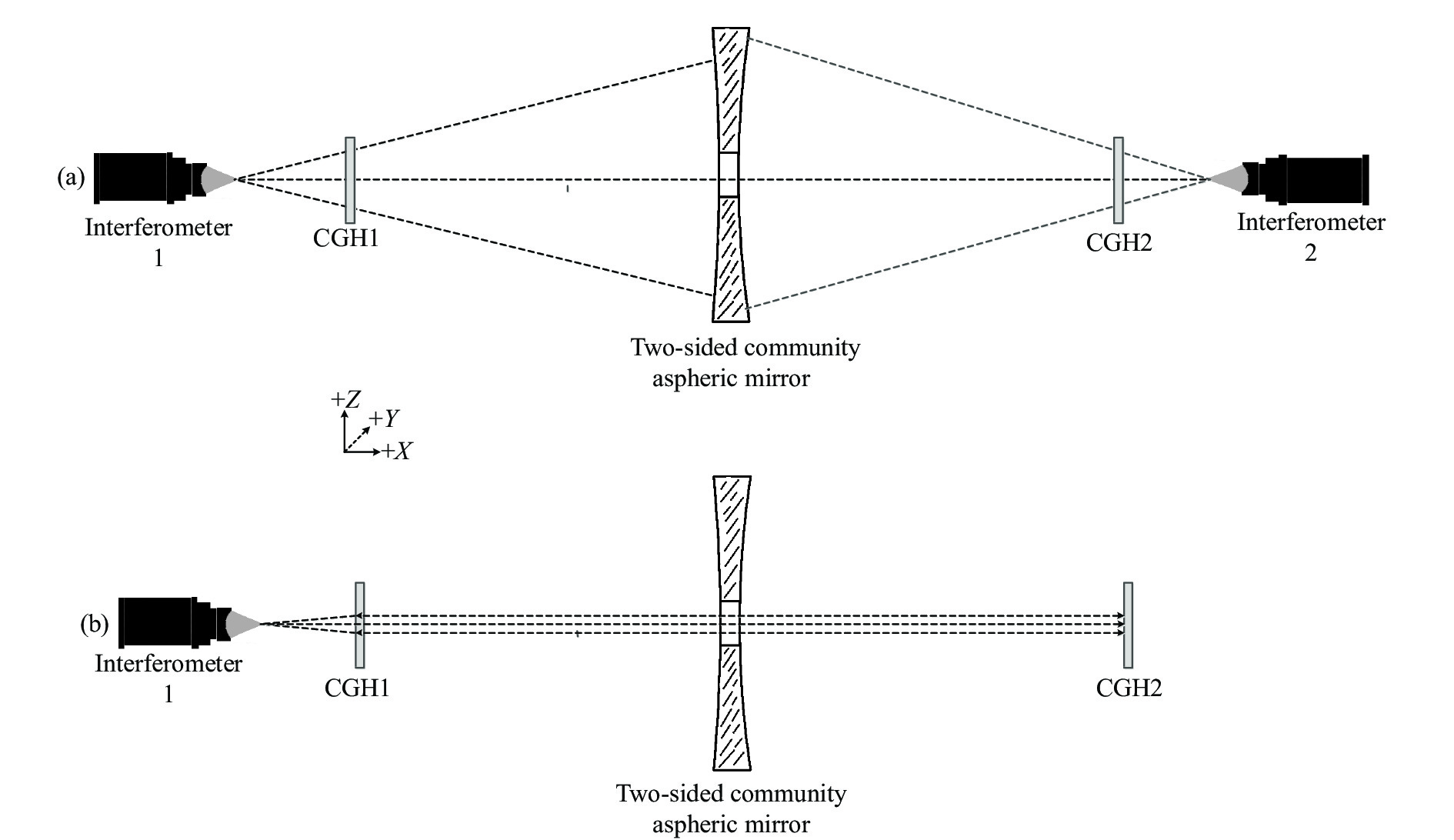
检测原理图如图1所示。图1(a)为用CGH分别测量共体非球面反射镜两个表面的光路。待测共体非球面反射镜表面分别为S1和S2,干涉仪1和CGH1测量非球面S1的表面面形,在干涉测量光路中,严格控制初级像差后,CGH1和非球面S1的光轴将达到高度一致。同理, CGH2和非球面S2的光轴也将一致,即CGH1和CGH2的光轴可分别表征S1和S2的光轴。设计时,CGH1和CGH2的光轴都垂直于其光学表面。图1(b)为测量两个CGH之间夹角的干涉测量光路。CGH在经过设计后,可使得干涉仪1发出的标准球面测试光波经CGH1后特定区域被调制为标准平面光波,光波经过CGH2后自准直返回,形成干涉条纹,解析干涉条纹波前倾斜,得到两CGH的夹角值θ。
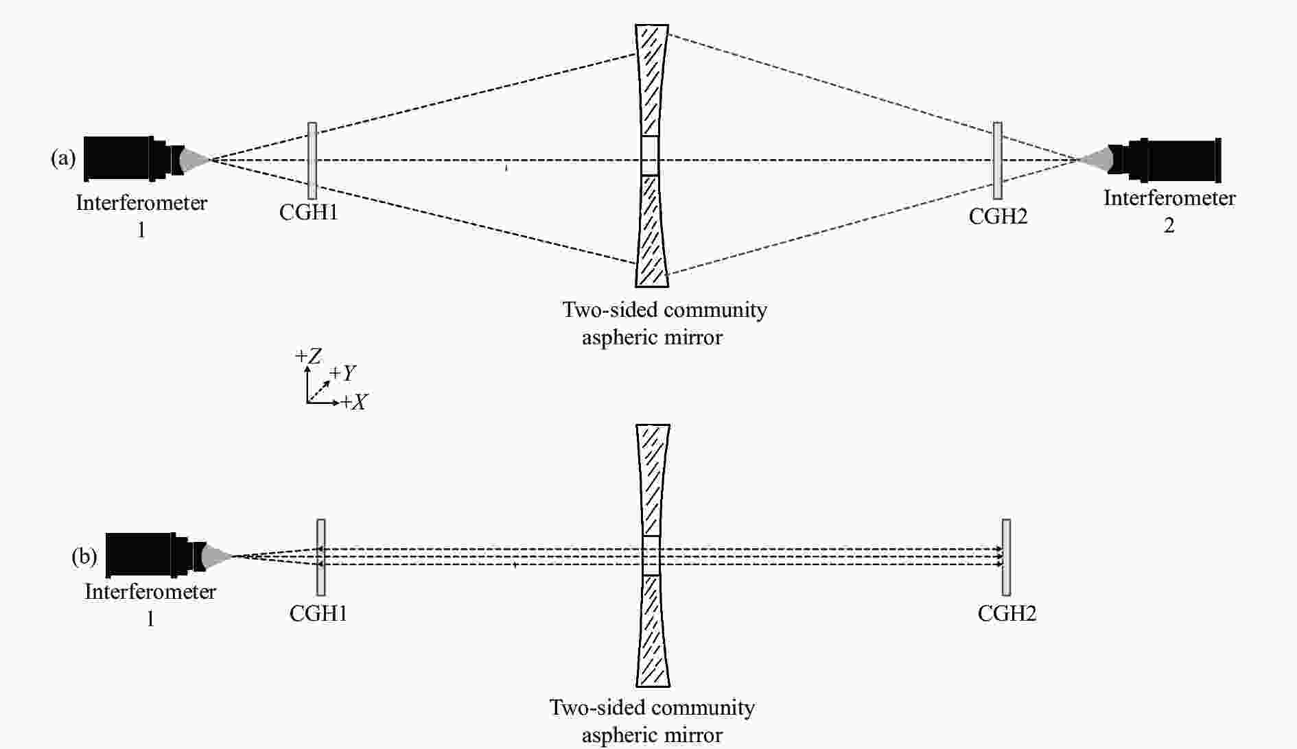
图 1 测量方案示意图
Figure 1. Schematic diagram of tesing system
如图2所示,依据非球面S1、S2的几何参数以及装置中光学元件的位置关系,将CGH1、CGH2上划分不同区域,包括零位测试区域A、对准区域B、夹角测试区域C。区域A用于测量两面共体非球面光学零件的表面面形误差,激光干涉仪发出的标准球面测试光波经过区域A后被调制为非球面光学零件表面一致的波前,从而形成干涉测量条件。激光干涉仪发出的标准球面测试光波经过区域B后自准直返回,形成干涉条纹,用于激光干涉仪和CGH补偿器的辅助对准。区域C用于测量CGH1和CGH2的夹角。

图 2 CGH区域分布图
Figure 2. Schematic diagram of CGH area
$$ {\theta }={\mathrm{arctan}}\left(\frac{2{T}}{{D}}\cdot {\lambda }\right) $$ (1) 式中:D为CGH补偿器表面区域C的口径;λ为干涉仪的激光λ;T为波前倾斜量,可分解成水平和垂直两个分量($ {T}_{x} $,$ {T}_{y} $),对应Zernike多项式对波前数据进行拟合的第二项和第三项系数。
-
针对一两面共体待测非球面反射镜进行了CGH补偿器的设计,待测两面共体非球面光学零件的非球面光学表面S1口径Φ500 mm,顶点曲率半径R0=560 mm,非球面系数K=−0.88;非球面光学表面S2口径Φ420 mm,顶点曲率半径R0=1558 mm,非球面系数K=−3。
CGH补偿器到非球面光学表面距离在数值上一般不超过非球面光学表面的顶点曲率半径R,在该范围内,CGH补偿器到非球面光学表面的距离越近,所需的测试区域A的口径越大。该距离在选择上应尽量使得CGH补偿器区域B的口径不大于100 mm。CGH补偿器到干涉仪的距离影响CGH补偿器加工的最小特征尺寸。设计选择合适的距离使得最小特征尺寸不小于5 μm。
根据待测两面共体非球面光学零件中非球面光学表面S1、S2 的几何参数,使用光学设计软件Zemax进行仿真设计。设置激光波长为632.8 nm,非球面光学表面S1与CGH1距离为500 mm,CGH1与干涉仪1的距离为150 mm,CGH补偿器的材料为熔融石英,厚度为6.35 mm。CGH1对准区域A、测试区域B、基准区域C参数如表1所示。
表 1 主镜CGH参数
Table 1. CGH parameters of the primary mirror
Aera Aperture/mm Binary2 polynomial coefficients A4 A6 A8 A10 A12 A 16-80 −7.195E+004 1.987E+003 −1.074E+002 5.878E+000 0 B 80-120 5.057E+001 −2.035E-002 7.053E-006 −1.387E-009 1.104E-013 C 0-16 −1.30E+003 3.448E-001 0 0 0 设置非球面光学表面S2与CGH2距离为1000 mm,CGH2与干涉仪2的距离为240 mm,CGH补偿器的材料为熔融石英,厚度为6.35 mm;CGH2对准区域A、测试区域B参数如表2所示。
表 2 四镜CGH参数
Table 2. CGH parameters of the fourth-mirror
Aera Aperture/mm Binary2 polynomial coefficients A4 A6 A8 A10 A12 A 16-70 −8.213E+004 2.156E+003 −1.129E+002 3.788E+000 0 B 70-115 6.184E+001 −3.051E-002 7.361E-006 −2.237E-009 6.345E-013 干涉仪光波经过CGH后分解为多个衍射级次,一般利用(1,1)级衍射光作为检测光波。其他衍射级次的光波经过镜面反射部分返回干涉仪,在干涉条纹中产生鬼像,影响检测结果。利用Zemax多重结构的方法对CGH的非工作衍射级次的杂光进行了分析,如图3所示。可以看出,检测系统设计上的旋转对称性导致杂光难以完全消除,但杂光反应在镜面上的分布已经很小。
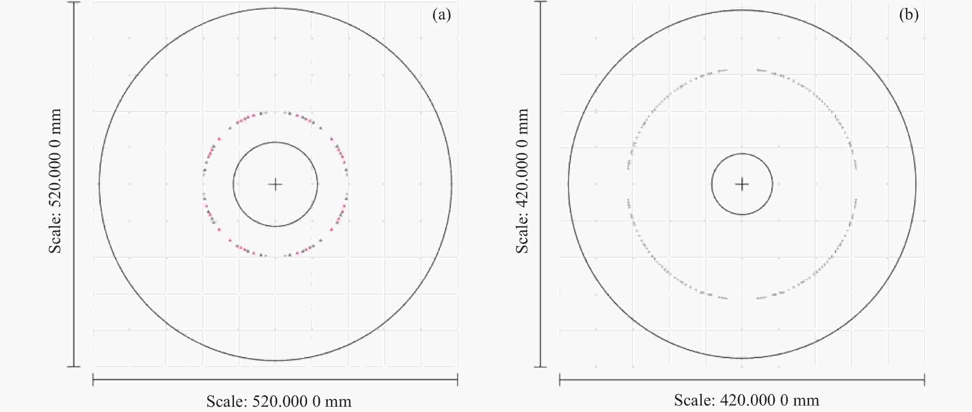
图 3 非工作衍射级次杂光在非球面S1和S2的分布
Figure 3. Distribution of non working diffraction level stray light on aspheric surfaces S1 and S2
-
干涉测试光路中,影响光轴一致性测量的误差源主要有CGH制造误差$ {\mathrm{\delta }}_{1} $、光路失调误差$ {\mathrm{\delta }}_{2} $、CGH1和CGH2之间夹角测试误差$ {\mathrm{\delta }}_{3} $。
CGH制造误差分为刻蚀误差和基板楔角误差。针对刻蚀误差,由于零位CGH采用离焦载频,刻蚀呈现旋转对称性,这种CGH刻蚀误差在工艺上主要表现为像散,不引入光轴测量误差。CGH基板制造工艺可保证楔角误差为0.5″,即$ {0.000\;14}^{°} $,引入的CGH制造误差$ {\mathrm{\delta }}_{1} $为$ {0.000\;14}^{°} $。
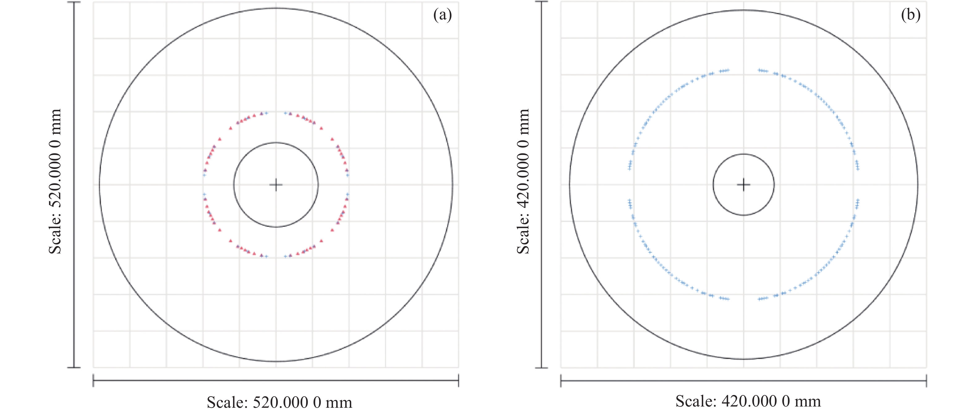
光路失调误差可分为干涉仪与CGH失调误差,CGH与被测非球面失调误差。针对干涉仪与CGH失调误差,对CGH1和CGH2的对准区域B进行了仿真分析,CGH与干涉仪失调量为$ {0.000\;14}^{°} $时,对准区干涉条纹分别为三根和两根,如图4所示。 因此,调整对准CGH使其对准区干涉条纹接近零条纹,实现干涉仪和CGH的高精度对准,引入的光轴偏差基本可以忽略。

图 4 CGH1、CGH2与干涉仪0.0001°的干涉条纹分布
Figure 4. Distribution of interference fringes when the angle between cgh and interferometer is 0.0001°
针对CGH与被测非球面失调误差,主要由干涉测试光路中难以完全消除彗差导致,通过六自由度电控平台做灵敏度测试,按干涉仪对于彗差的测试精度为0.01λ计算,非球面S2光路失调误差为$ {0.000\;22}^{°} $,非球面S1光路失调误差为$ {0.000\;03}^{°} $。
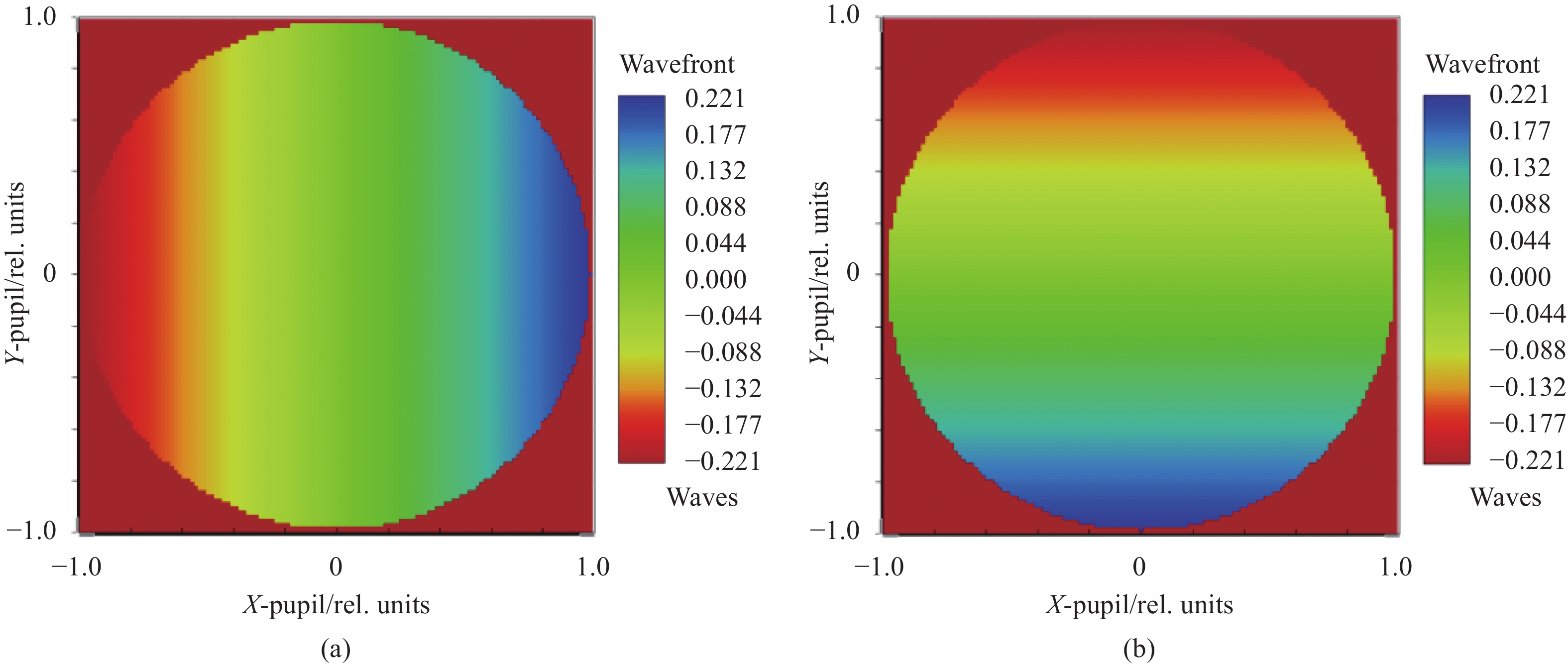
针对CGH1和CGH2之间夹角测试误差,主要由波前倾斜的测试不确定度引起, 对CGH1的区域C的测试灵敏度进行了仿真分析,设置CGH1和CGH2的夹角为0.001°,仿真得到的波前倾斜PV值为0.44λ,对应Zernike系数为0.22λ,如图5所示。
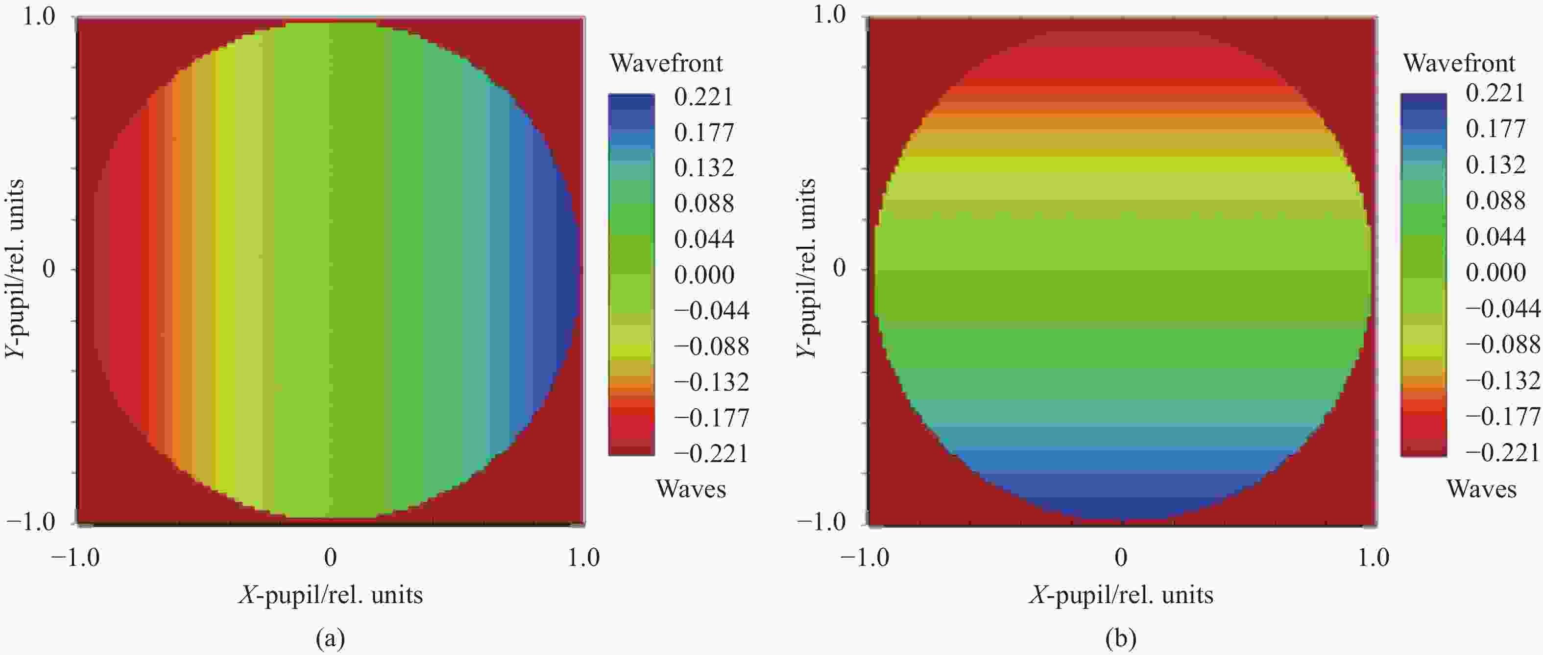
图 5 CGH1和CGH2的夹角为0.001°的波前仿真
Figure 5. Wavefront simulation when the angle between CGH1 and CGH2 is 0.001°
由于波前倾斜的干涉测试精度为0.05λ(PV),对应夹角误差测量不确定度为0.00011°。波前倾斜量为实际倾斜量的2倍,根据公式(1),对应的夹角误差$ {\mathrm{\delta }}_{3} $为0.000055°。综上,整个检测光路的夹角测试误差为$ \sqrt{{0.000\;14}^{2}\;+\;{0.000\;22}^{2}\;+\;{0.000\;03}^{2}\;+\;{0.000\;055}^{2}} $ =0.00027°,约合1"。
-
根据以上光路参数设计制造的CGH1、CGH2, 搭建干涉检测光路进行了光轴一致性测试,现场照片如图6所示,CGH1区域C对应的干涉条纹如图7所示,干涉仪数据理解析出的波前倾斜为(1.544$ {\lambda } $,0.441$ {\lambda } $),根据公式(1)计算出光轴夹角为($ {0.007\;0}^{°} $,$ {0.002\;0}^{°} $)。

图 6 光轴偏差测量现场
Figure 6. Testing site of optical axis deviation

图 7 CGH1的干涉条纹分布
Figure 7. Distribution of interference fringes in CGH1
为验证测量结果的准确性,使用经纬仪测量了两片CGH的夹角,记录如表3所示。
根据测量结果计算:水平夹角为$ {180.007\;1}^{\circ} $−$ {0}^{\circ}= $0.0071°,垂直夹角为 $ {180}^{\circ} $−$ {90.489\,0}^{\circ} $−$ {89.512\,9}^{\circ} $=−0.0019°,与文中所用方法测量结果基本一致。
使用轮廓仪法对干涉测量方法结果进行了比对验证,分别扫描主镜和四镜面形轮廓,拟合出光轴相对于各自端面基准的夹角值($ {0.003\;6}^{°} $,$ {0.000\;5}^{°} $),三坐标测量机测量出主镜端面基准和四镜端面基准的夹角($ {0.003\;5}^{°} $,$ {0.001\;5}^{°} $),统一坐标系后,主镜和四镜的光轴偏差为($ {0.007\;1}^{°} $,$ {0.002\;0}^{°} $),测量现场照片如图8所示。
表 3 经纬仪测量结果
Table 3. Theodolite measurement results
Measurement item 1st 2nd 3rd CGH 1 Horizontal $ {0}^{°} $ $ {0}^{°} $ $ {359.999\;8}^{°} $ Vertical $ {89.512\;9}^{°} $ $ {89.512\;9}^{°} $ $ {89.512\;9}^{°} $ CGH 2 Horizontal $ {180.007\;2}^{°} $ $ {180.007\;1}^{°} $ $ {180.007\;0}^{°} $ Vertical $ {90.489\;0}^{°} $ $ {90.489\;1}^{°} $ $ {90.489\;0}^{°} $ 
图 8 三坐标测量机(a)与轮廓仪测试现场(b)
Figure 8. CMM (a) and profileometer measurement site (b)
-
提出了一种两面共体非球面反射镜光轴一致性检测方法,该方法将两个非球面表面的光轴通过精密调整和严格标定后引出到CGH补偿器上,CGH特定区域发出平行光,经另一片CGH反射后在干涉仪中形成表征两片CGH补偿器夹角的干涉条纹,解算干涉条纹波前倾斜得出两非球面的光轴偏差。针对一口径Φ500 mm的两面共体非球面反射镜,设计研制了CGH片,搭建检测光路完成了测试,解算干涉条纹波前倾斜得到的光轴夹角为($ {0.007\;0}^{°} $,$ {0.002\;0}^{°} $),使用经纬仪实测的两片CGH的夹角为($ {0.007\;1}^{°} $,$ {0.001\;9}^{°} $),使用轮廓仪的检测结果为($ {0.007\;1}^{°} $,$ {0.002\;0}^{°} $),三者显示出较高的一致性。对影响光轴测试精度的误差源进行了分析,该方法的检测精度为$ {0.000\;27}^{°} $,具有直观性强、检测精度高的优点。
Research on high precision testing method for mirror optical axis of two-sided community aspheric mirror (invited)
-
摘要: 同轴四反式光学系统的研制可采用非球面主镜和四镜一体化成型制造法,该方法极大地降低了系统零件复杂度,同时减轻了整机质量,提高了装机效率,但对后期光学系统装调的自由度产生了约束,因此,在镜面制造过程中,两者的光轴一致性需要精确测量及控制。在现有干涉测量法的基础上,提出了一种检测两面共体非球面镜光轴一致性的方法。在干涉检测光路中,两个非球面表面的光轴通过精密调整和严格标定后分别引出到两个计算全息片(CGH)补偿器上,CGH经过设计后,其特定区域可发出平行光,经另一片CGH反射后在干涉仪中形成表征两片CGH夹角的干涉条纹,解算干涉条纹的波前倾斜可得出两非球面的光轴偏差,对一两面共体待测非球面光学零件进行了CGH设计和检测光路的误差分析,显示测试精度可以达到1″。设计投产了CGH补偿器,搭建干涉检测光路,完成了光轴一致性的测量,数据处理解析出的波前倾斜为(1.544λ,0.441λ),计算出光轴夹角为(0.007 0°, 0.002 0°),使用经纬仪复测的两片CGH的夹角为(0.007 1°, 0.001 9°)。使用轮廓仪法对干涉测量法结果进行了比对验证,分别扫描主镜和四镜的面形轮廓,统一坐标系后,主镜和四镜的光轴夹角为(0.007 1°, 0.002 0°),三者显示出较高的一致性。该方法具有直观性强、检测精度高的优点。Abstract:
Objective When the aspheric primary mirror and fourth-mirror integrated molding manufacturing method is used in coaxial four-mirror optical system, the complexity of system parts and weight of the whole machine would be reduced, and the installation efficiency could be improved greatly. Besides, the degree of freedom is constrained in later optical system assembly, so the optical axis of the two aspheric mirror needs maintain a high degree of consistency in the mirror manufacturing process. On the basis of the existing interferometry method, a new method is proposed to measure the optical axis deviation of two-sided community aspheric mirror. Methods Based on the existing interferometric measurement method, a method of calculating the optical axis consistency of CGH interferometric wavefront tilt is proposed. The principle of the measurement method is introduced in detail (Fig.1). Figure 1 (a) shows the CGH optical measurement system of the two-sided community aspheric mirror. The surface of the aspheric mirror to be measured is S1 and S2. Interferometer 1 and CGH1 are used to measure the surface shape of the aspheric surface S1. The optical axes of CGH1 and aspheric S1 will reach a high consistency after the primary aberration is controlled strictly in the interferometric measurement optical system. Similarly, the optical axes of CGH2 and aspheric S2 would also be consistent. The optical axes of CGH1 and CGH2 would respectively characterize the optical axes of S1 and S2. The optical axes of CGH1 and CGH2 are both perpendicular to their optical surfaces in the design model. Figure 1 (b) shows the interferometric optical system for measuring the angle between two CGHs. CGH1 is designed to emit parallel laser in a specific area, and after reflection by CGH2, an interference fringe representing the angle between two CGH compensators is formed in the interferometer. The optical axis deviation of the two aspheric surfaces can be obtained by solving wavefront tilt of the interference fringe (Eq.1). Results and Discussions For a diameter Φ500 mm two-sided aspherical mirror, the optical measurement model was designed and simulated, the design parameters were given (Tab.1-2). The diffraction stray light in the measurement optical path was simulated and analyzed (Fig.3). The error sources affecting the measurement accuracy (Fig.4-5) were decomposed. The main error sources are CGH manufacturing error, optical path misalignment error, and angle measurement error between CGH1 and CGH2. Simulation analysis shows that the measurement accuracy is 1 s. Two CGH were designed and processed, and the interference measurement optical system was built (Fig.6). The optical axis angle was calculated as (0.007 0°, 0.002 0°) when the wavefront tilt was (1.544λ, 0.441λ). The angle between the two CGH remeasured by theodolite was (0.007 1°, 0.001 9°). The profiler method was used to compare and verify CGH measurement result, the surface contours of the primary mirror and the four mirrors was scaned respectively, and the optical axis deviation was (0.007 1°, 0.002 0°) after unifying in one coordinate system. Conclusions In order to solve the problem of optical axis consistency measurement of two-sided aspherical mirror, a new method of calculating CGH interference wavefront tilt was proposed based on the existing interferometric method. The principle of the method was introduced, the simulation design and error analysis of the measurement optical system were carried out, which show 1 s accuracy. The optical system was built and the method of profilometer was compared to verify the measurement accuracy of the method. This method has the advantages of intuitiveness and high measurement accuracy, and has been successfully applied to the integrated molding manufacturing of coaxial four-trans optical system. -
图 3 非工作衍射级次杂光在非球面S1和S2的分布
Figure 3. Distribution of non working diffraction level stray light on aspheric surfaces S1 and S2
图 4 CGH1、CGH2与干涉仪0.0001°的干涉条纹分布
Figure 4. Distribution of interference fringes when the angle between cgh and interferometer is 0.0001°
图 5 CGH1和CGH2的夹角为0.001°的波前仿真
Figure 5. Wavefront simulation when the angle between CGH1 and CGH2 is 0.001°
表 1 主镜CGH参数
Table 1. CGH parameters of the primary mirror
Aera Aperture/mm Binary2 polynomial coefficients A4 A6 A8 A10 A12 A 16-80 −7.195E+004 1.987E+003 −1.074E+002 5.878E+000 0 B 80-120 5.057E+001 −2.035E-002 7.053E-006 −1.387E-009 1.104E-013 C 0-16 −1.30E+003 3.448E-001 0 0 0  下载: 导出CSV
表 2 四镜CGH参数
Table 2. CGH parameters of the fourth-mirror
Aera Aperture/mm Binary2 polynomial coefficients A4 A6 A8 A10 A12 A 16-70 −8.213E+004 2.156E+003 −1.129E+002 3.788E+000 0 B 70-115 6.184E+001 −3.051E-002 7.361E-006 −2.237E-009 6.345E-013
下载: 导出CSV
表 3 经纬仪测量结果
Table 3. Theodolite measurement results
Measurement item 1st 2nd 3rd CGH 1 Horizontal $ {0}^{°} $ $ {0}^{°} $ $ {359.999\;8}^{°} $ Vertical $ {89.512\;9}^{°} $ $ {89.512\;9}^{°} $ $ {89.512\;9}^{°} $ CGH 2 Horizontal $ {180.007\;2}^{°} $ $ {180.007\;1}^{°} $ $ {180.007\;0}^{°} $ Vertical $ {90.489\;0}^{°} $ $ {90.489\;1}^{°} $ $ {90.489\;0}^{°} $
下载: 导出CSV
-
[1] 胡永富, 解 静, 吴建福. 轻小型推扫视频一体化相机设计与验证[J]. 半导体光电, 2020, 41(2): 0273-0277. Hu Yongfu, Xie Jing, Wu Jianfu. Design and verification of light and small push-broom and video integrated camera [J]. Semiconductor Optoelectronics, 2020, 41(2): 273-277. (in Chinese) [2] 李维, 刘勋, 张维畅, 等. 天基边缘智能光学遥感技术构想[J]. 航天返回与遥感, 2022, 43(4): 1-11. Li Wei, Liu Xun, Zhang Weichang, et al. Space based edge intelligent remote sensing [J]. Spacecraft Recovery & Remote Sensing, 2022, 43(4): 1-11. (in Chinese) [3] Jiang Haibin, Luo Shikui, Cao Dongjing. Technology of high-density and high-resolution camera of GF-2 satellite [J]. Spacecraft Recovery & Remote Sensing, 2015, 36(4): 25-33. (in Chinese) [4] 曹海翊, 张新伟, 赵晨光, 等. 高分七号卫星总体设计与技术创新[J]. 中国空间科学技术, 2020, 40(5): 1-9. Cao Haiyi, Zhang Xinwei, Zhao Chenguang, et al. System design and key technolongies of the GF-7 satellite [J]. Chinese Space Science and Technology, 2020, 40(5): 1-9. (in Chinese) [5] 孙立, 杨居奎, 王玉诏, 等. 主被动一体化多波束激光雷达设计与实现[J]. 航天返回与遥感, 2022, 43(6): 27-35. Sun Li, Yang Jukui, Wang Yuzhao, et al. Design and implementation of the active-passive multi-channel LiDAR [J]. Spacecraft Recovery & Remote Sensing, 2022, 43(6): 27-35. (in Chinese) [6] Zhao Yuchen, Hu Changhong, Lv Hengyi. Design of high-density coaxial four-mirror optical system with field-bias and multi-light-channel coupled [J]. Infrared and Laser Engineering, 2021, 50(3): 20200197. (in Chinese) [7] 周运义, 林丽娜, 彭章贤. 精密反射式定心仪设备设计[J]. 光 学 与 光 电 技 术, 2020, 18(5): 68-74. Zhou Yunyi, Lin Lina, Peng Zhangxian. Design of precision reflective centering instrument [J]. Optics & Optoelectronic Technology, 2020, 18(5): 68-74. (in Chinese) [8] 陈钦芳, 徐昌杰. 轴对称非球面透镜光轴共轴度的测量研究[J]. 应用光学, 2008, 29(6): 870-873. Chen Qinfang, Xu Changjie. Coaxial measurement of axisymmetric aspheric lens [J]. Journal of Applied Optics, 2008, 29(6): 870-873. (in Chinese) [9] Fan Xinrui, Diao Xiaofei, Wu Jianwei. High-precision profile measurement method for axisymmetric aspheric mirror (invited) [J]. Infrared and Laser Engineering, 2022, 51(9): 20220500. (in Chinese) [10] Jiao Songfeng, Xie Qiming, Liu Yao. Optical aspheric surface profile testing technology [J]. Infrared Technology, 2023, 45(5): 534-540. (in Chinese) [11] Henselmans R. Non-contact measurement machine for freeform optics[D]. Eindhoven: Technische Universiteit Eindhoven, 2009. [12] Zhang Xuemin, Wei Ruyi, Yu Tao. A method to measure off-axis fabrication and off-axis angle of axis aspheric mirror precisely [J]. Chinese Journal of Lasers, 2014, 41(4): 0416001. (in Chinese) [13] 王 聪, 陈佳夷, 栗孟娟. 基于干涉测量的 Ф1.3 m 非球面反射镜定心[J]. 红外与激光工程, 2020, 49(1): 0113001. Wang Cong, Chen Jiayi, Li Mengjuan. Centering of Ф1.3 m aspheric reflector based on interferometry [J]. Infrared and Laser Engineering, 2020, 49(1): 0113001. (in Chinese) [14] Li Bin, Chen Jiayi, Wang Haichao. Optical axis elicitation method for ellipsoidal mirror [J]. Journal of Applied Optics, 2018, 39(6): 791-795. (in Chinese) [15] Ma Zhen, Li Yingcai, Fan Xuewu. Study on optical centering of aspheric mirror by interferometry [J]. Acta Photonica Sinica, 2008, 37(4): 1455-1458. (in Chinese) -

 点击查看大图
计量
- 文章访问数: 131
- HTML全文浏览量: 23
- PDF下载量: 35
- 被引次数: 0

