


-
激光无线能量传输(Laser Wireless Power Transmission, LWPT)通过激光以自由空间传输形式将能量从发射端传输到接收端,在接收端用光电池将光能转换为电能为负载供电[1−2]。相比于其他无线能量传输技术,LWPT技术具有传输距离长、传输效率高和方向性好等优点,在无人机空中续航、航天器供能和物联网设备协能通信等领域有广泛的应用前景[3−5]。
在LWPT系统中,最大功率点跟踪(Maximum Power Point Tracking, MPPT)技术通过实时调整接收端的电路参数,使得激光光电池的输出功率达到最大值,是提高能量传输效率的关键因素[6]。由于跟瞄系统误差和物体遮挡的影响,光电池阵列会受到不均匀激光辐照,阵列的组串内光电池间产生不同的光生电流,导致阵列的组串内光电池间电流失配,其输出伏安特性呈多峰状态,且输出功率明显下降[7-8]。针对该问题,研究人员提出了许多提升MPPT追踪速度及精度的算法,如改进的蝙蝠算法[9]、快速电压定位算法[10]和神经网络算法[11]等。这些算法对于多峰值功率点追踪具有非常好的性能。然而,在受到不均匀分布激光辐照时,如何降低阵列的组串内光电池间的电流失配现象鲜有人研究。
采用分布式最大功率点追踪(Distributed Maximum Power Point Tracking, DMPPT)技术,可以有效降低阵列的组串内各电池间的电流失配现象[12−14]。DMPPT技术最早应用于解决太阳能发电中的电流失配问题,是太阳能领域的研究热点。在算法改进方面,结合改进的粒子群优化过程,采用蛙跳算法衍生出的分组概念来加快收敛速度[15]和引入学习系数提高算法全局搜索能力的改进麻雀搜索算法,得到与扰动观测法和粒子群优化算法相比更加快速、准确的追踪速度[16];在控制器设计方面,为了提高分布式最大功率点追踪系统的稳定性和鲁棒性,采用模型预测控制方法来实现更精确的功率跟踪和故障诊断,更准确地预测最优工作点[17]和采用分段的反激式差分功率结构,最大限度的减小转换器的功率损耗[18];在硬件方面,使用新型半导体材料和器件[19−20],以及集成度更高的功率电子元件[21]和传感器[22−23]等。文中针对LWPT中的电流失配问题,根据LWPT中激光辐照功率密度高但单块池GaAs电池功率低的特点,将DMPPT技术应用到LWPT系统,减少光电阵列组串内的电池间电流失配,并提出用并联型Boost(PT-Boost)电路替换传统Boost电路,降低输入电流纹波,从而有效提升了DMPPT系统各MPPT子模块的追踪精度和DMPPT的整体电路效率。
-
如图1所示,DMPPT系统包括光电池阵列、滤波装置、DC/DC转换器、DMPPT控制器和负载。滤波装置采用大容量电容滤除光电池输出电压的高频噪声后,DMPPT控制器检测每个光电池当前的输出电流和输出电压,并计算出当前功率,再利用扰动观测算法输出占空比变化的PWM信号至各个DC/DC转换器,DC/DC转换器通过接收到的变化的PWM实时调整每个光电池的输出电流和输出电压,确保各个光电池寻找到最大功率点并在最大功率点附近工作,同时各个DC/DC转换器的输出端串联起来以确保整个DMPPT系统的输出总功率最大化。为了实现该技术,首先需要对各模块进行理论模型分析以及参数确定。
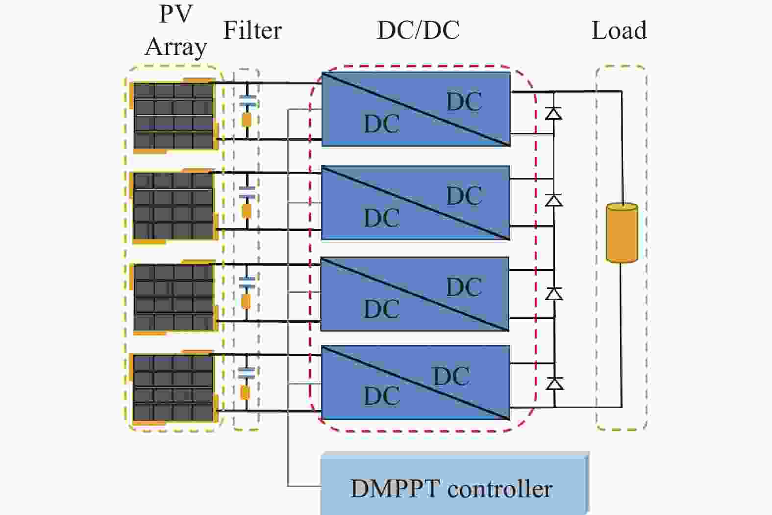
图 1 DMPPT系统框图
Figure 1. Block diagram of DMPPT system
-
当n个光电池串联组成光电池阵列,其阵列结构如图2所示。
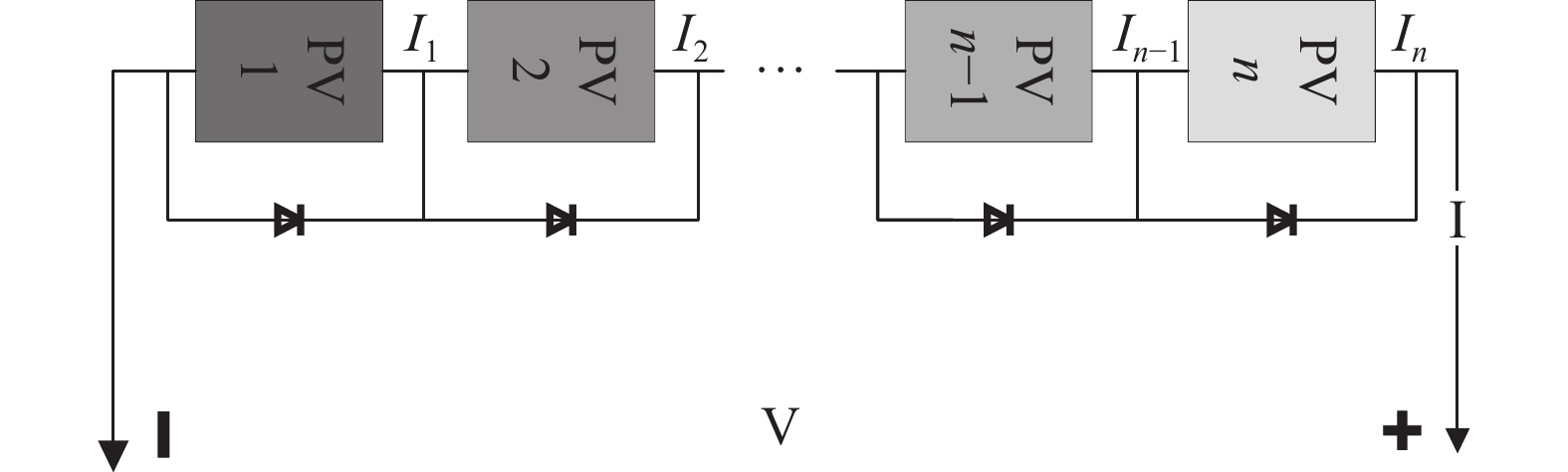
图 2 串联型光电池阵列结构
Figure 2. Structure of tandem PV array
每个光电池的光生电流分别为Isc1、Isc2、···、Isc(n-1)、Iscn。忽略光电池串并联电阻,光电池阵列的输出电流为:
$$ \begin{gathered} {I_1} = {I_{sc1}} - {I_0}({{\mathrm{e}}^{{{q{V_1}}}/{{KT}}}} - 1) \\ {I_2} = {I_{sc2}} - {I_0}({{\mathrm{e}}^{{{q{V_2}}}/{{KT}}}} - 1) \\ \begin{array}{*{20}{c}} {}&{}&{} \end{array} \cdots \\ {I_{{n}}} = {I_{sc{{n}}}} - {I_0}({{\mathrm{e}}^{{{q{V_{{n}}}}}/{{KT}}}} - 1) \\ \end{gathered} $$ (1) 式中:I0为二极管反向饱和电流;电荷量q值为1.6×10⁻¹⁹ C;K为玻尔兹曼常数1.38×10⁻²³ J/K;T为电池表面温度;I1、I2、···、In分别为各光电池的输出电流;V1、V2、···、Vn分别为各光电池的输出电压,且满足关系:
$$ {V_{{m}}} = \frac{{KT}}{q}\ln \left(\frac{{{I_{sc{{m}}}} + {I_0} - I}}{{{I_0}}}\right) $$ (2) 式中:m取值范围为(1, n),将输出电流分为[Isc1, Isc2)、[Isc2, Isc3)、···、[Isci, Isc(i+1))、···、[Iscn, 0],当输出电流I在[Isc1, Isc2)区间,除了PV1电池外,其他电池并联的二极管均流过电流,因此其他电池两端电压也被钳制到0,则输出电流I在[Isc1, Isc2)区间时输出电压V为:
$$ V = {V_1} = \frac{{KT}}{q}\ln \left(\frac{{{I_{sc1}} + {I_0} - I}}{{{I_0}}}\right) $$ (3) 同理可得出,输出电流在区间[Isc2, Isc3)、[Isc3, Isc4)、···、[Iscn, 0]内输出电压为:
$$ \left\{\begin{aligned} V & =V_1+V_2= \\ & \dfrac{K T}{q}\left[\ln \left(\dfrac{I_{s c 1}+I_0-I}{I_0}\right)+\ln \left(\dfrac{I_{s c 2}+I_0-I}{I_0}\right)\right] \\ V & =V_1+V_2+V_3= \\ & \dfrac{K T}{q}\left[\begin{array}{l} \left.\ln \left(\dfrac{I_{s c 1}+I_0-I}{I_0}\right)+\ln \left(\dfrac{I_{s c 2}+I_0-I}{I_0}\right)+\right] \\ \ln \left(\dfrac{I_{s c 3}+I_0-I}{I_0}\right) \end{array}\right] \\&\cdots \\ V & = V_1+V_2+\cdots+V_{{n}} =\\ & \dfrac{K T}{q}\left[\begin{array}{l} \left.\ln \left(\dfrac{I_{s c 1}+I_0-I}{I_0}\right)+\ln \left(\dfrac{I_{s c 2}+I_0-I}{I_0}\right)+\cdots+\right] \\ \ln \left(\dfrac{I_{s c n}+I_0-I}{I_0}\right) \end{array}\right. \end{aligned}\right. $$ (4) 由公式(3)、(4)可知输出电压为分段函数。根据公式(3)、(4)可以利用建模软件搭建电池阵列输出特性模型,如图3(a)所示,当激光辐照度均匀时,光电池阵列各电池光生电流Isc相同,则P-V曲线如图3(b)所示呈现单峰,当激光辐照度不均匀时,光电池阵列各电池光生电流Isc不相同,则P-V曲线呈现多峰状态,且输出功率下降。由于该光电池阵列输出特性模型没有约束各电池的光生电流大小,因而也适用于由于瞄准系统误差和物体遮挡引起的激光辐照度变化的场景中。
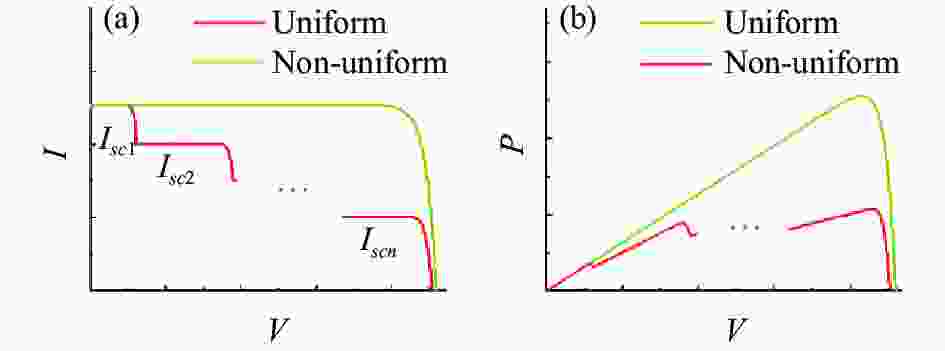
图 3 光电池输出特性。(a) I-V曲线;(b) P-V曲线
Figure 3. PV cell output characteristics. (a) I-V curve; (b) P-V curve
-
为了提升DMPPT的追踪效率,文中采用PT-Boost电路作为DMPPT系统的DC/DC转换器。该电路所需的器件有两个相同的输入电感L1、L2,滤波电容Cin,两个相同的NMOS管M1、M2,两个相同的PMOS管M3、M4,储能电容Cout和负载Ro。PT-Boost电路拓扑如图4所示。
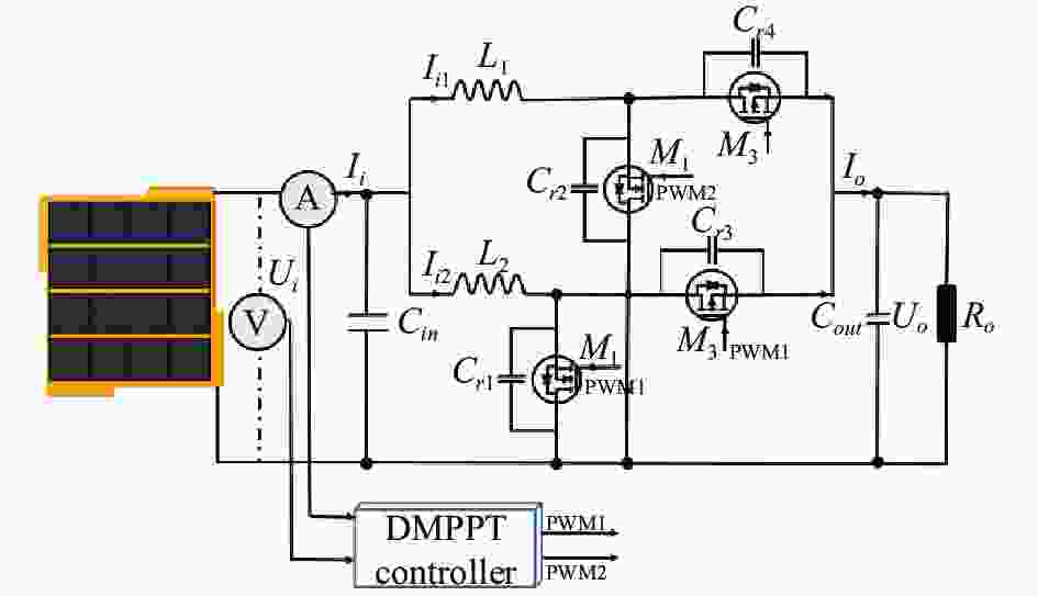
图 4 PT-Boost电路拓扑
Figure 4. Schematic diagram of PT-Boost circuit
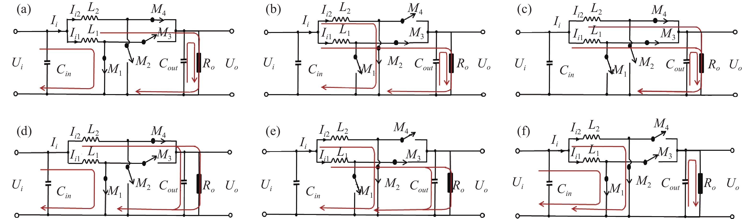
其中M1、M2、M3、M4的开断触发都在同一周期内且M1、M3开断相位相同,M2、M4开断相位相同,M1与M2的开断相位相差180°。在电路连续工作情况下,该电路有六种工作状态,PT-Boost电路在六种工作状态下的等效电路如图5所示。当占空比D的范围为[0.1,0.5]时,PT-Boost电路有三种状态模式:
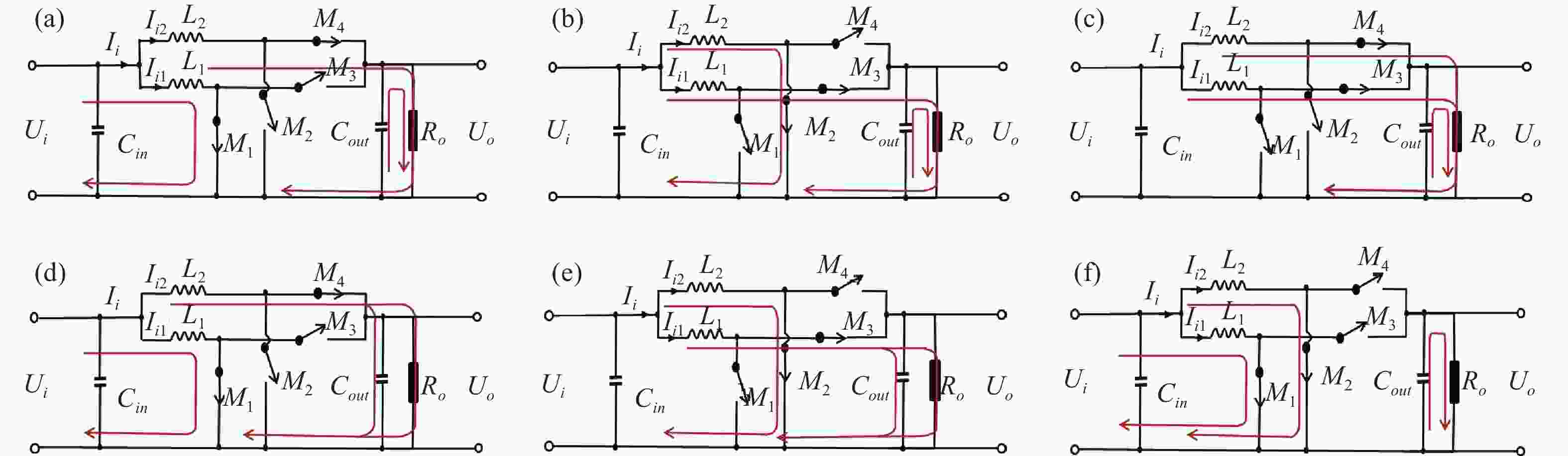
图 5 PT-Boost 电路的六种工作状态模式。(a)状态 1; (b)状态 2; (c)状态 3; (d)状态 4; (e)状态 5; (f)状态 6
Figure 5. Equivalent circuit diagrams of PT-Boost for six operating states. (a) S1; (b) S2; (c) S3; (d) S4; (e) S5; (f) S6
状态1:如图5(a)所示,M1和M4同时开通,M2和M3同时关断,此时电感L1电流Ii1增大,电感L2电流Ii2减小,电感L1储能,电感L2和电容Cout同时为负载R0供能,输入电流Ii增大。
状态2:如图5(b)所示,M1和M4同时关断,M2和M3同时开通,此时电感L2的电流Ii2增大,电感L1的电流Ii1减小,电感L2储能,电感L1和电容Cout同时为负载Ro供能,输入电流Ii增大。
状态3:如图5(c)所示,M1和M2同时关断,M3和M4同时开通,此时电流Ii1和Ii2均减小,电感L1、L2和电容Cout同时为负载Ro供能,输入电流Ii减小。
当占空比D的范围为(0.5,0.9]时,PT-Boost电路有三种状态模式:
状态4:如图5(d)所示,M1和M4同时开通,M2和M3同时关断,此时电感L1电流Ii1增大,电感L2电流Ii2减小,电感L1储能,电感L2为电容Cout和负载Ro同时供能,输入电流Ii减小。
状态5:如图5(e)所示,M1和M4同时关断,M2和M3同时开通,此时电感L2电流Ii2增大,电感L1电流Ii1减小,电感L2储能,电感L1为电容Cout和负载Ro同时供能,输入电流Ii减小。
状态6:如图5(f)所示,M1和M2同时开通,M3和M4同时关断,此时电流Ii1和Ii2均增大,电容Cout为负载Ro供能,输入电流Ii增大。
由状态图可知,PT-Boost电路利 用电感L1、L2分流后,电感L1、L2的电流升降呈相反的趋势,这种状态下可以减小电流的纹波,其电流纹波公式如下:
$$ \Delta {I_1} = \left\{ {\begin{array}{*{20}{l}} {\dfrac{{{U_{{i}}}TD}}{{{L_1}}} = \dfrac{{{U_{{o}}}T(1 - D)}}{{{L_1}}}\begin{array}{*{20}{c}} {\begin{array}{*{20}{l}} {}&{} \end{array}}&{} \end{array}10 {\text{%}} < D \leqslant 50 {\text{%}} } \\ {\dfrac{{{U_{{i}}}TD(2D - 1)}}{{{L_1}(1 - D)}} = \dfrac{{{U_{{o}}}T(2D - 1)}}{{{L_1}}}\;\;50 {\text{%}} < D \leqslant 90 {\text{%}} } \end{array}} \right. $$ (5) $$ \Delta {I_2} = \left\{ {\begin{array}{*{20}{l}} {\dfrac{{{U_{{i}}}TD(2D - 1)}}{{{L_2}}} = \dfrac{{{U_{{o}}}T(2D - 1)}}{{{L_2}D}}\;\;10 {\text{%}} < D \leqslant 50 {\text{%}} } \\ {\dfrac{{{U_{{i}}}T(1 - D)}}{{{L_2}}} = \dfrac{{{U_{{o}}}TD}}{{{L_2}}}\begin{array}{*{20}{c}} {}&{}&{} \end{array}50 {\text{%}} < D \leqslant 90 {\text{%}} } \end{array}} \right. $$ (6) 式中:Ui为输入电压;Uo为输出电压;T为MOS管开断周期。
为了减小PT-Boost电路的电流纹波噪声,需要对输入电容Cin,储能电容Cout,电感L1、L2,NMOS管M1、M2,PMOS管M3、M4的参数进行合理设计,各器件参数根据以下公式设计:
$$ {L}_{1}=\frac{{U}_{{i}}D(2D-1)}{\Delta {I}_{i1}f(1-D)},\begin{array}{cc}& {L}_{2}=\dfrac{{U}_{{i}}(1-D)}{\Delta {I}_{i2}f}\end{array} $$ (7) $$ {C}_{{in}}=\frac{D{I}_{i}}{(1-D){U}_{i}{}^{2}\Delta Uf},\begin{array}{cc}& {C}_{{out}}=\dfrac{2D{U}_{o}{I}_{{i}}}{{U}_{i}f\Delta U}\end{array} $$ (8) -
DMPPT系统的DC/DC转换器由n个输出端相互串联的PT-Boost电路所组成。其输出特性分析如下。
定义状态向量为:
$$ {{x}} = {({{{x}}_1},{{{x}}_2},{{{x}}_3},\cdots,{{{x}}_{{n}}})^{\mathrm{T}}} $$ (9) 式中:n为串联DC/DC转换器的数量。定义xj $ \in $ R1×3且j={1,2,3,···,n}为:
$$ {{{x}}_j} = ({x_{j1}},{x_{j2}},{x_{j3}}) = ({U_i}_j,{I_{ij}},{U_{oj}}) $$ (10) 式中:Uij为第j个DC/DC模块滤波电容Cin处电压;Iij为第j个DC/DC模块输入电流;Uoj为输出储能电容Cout处的电压,其数字模型可以简化成以下的形式:
$$ {{\dot x}} = {{A}}{\text{x + }}\sum\limits_{i = 1}^n {{g_j}({\text{x}})} {U_{ij}} + {{D}}{I_{ij}} + {{f}}{U_o}_j $$ (11) 其中,A $ \in $ R3n×3n定义为:
$$ {{A}} = {\left[ {\begin{array}{*{20}{c}} {{{{A}}_{{1}}}}&{{O}}& \cdots &{{O}} \\ {{O}}&{{{{A}}_{{2}}}}& \cdots &{{O}} \\ \vdots & \vdots & \ddots & \vdots \\ {{O}}&{{O}}& \cdots &{{{{A}}_{{n}}}} \end{array}} \right]_{n \times n}} $$ (12) O $ \in $ R3×3为零矩阵,并且Aj $ \in $ R3×3为:
$${A}_{{j}}=\left[\begin{array}{ccc} 0 & -1 / C_{ {in }} & 0 \\ 2 /\left(L_1+L_2\right) & 0 & -2 /\left(L_1+L_2\right) \\ 0 & -1 / C_{ {out }} & 0 \end{array}\right]_{3 \times 3} $$ (13) gj(x) $ \in $R3n × 1为:
$$ \begin{gathered} {g_1}({{x}}) = {[g({{{x}}_1}),0,0,\cdots,0]^{\mathrm{T}}} \\ {g_2}({{x}}) = {[0,g({{{x}}_2}),0,\cdots,0]^{\mathrm{T}}} \\ \begin{array}{*{20}{c}} {}&{}&{}&{} \end{array}\cdots\cdots \\ {g_n}({{x}}) = {[0,0,0,\cdots,g({{{x}}_{{n}}})]^{\mathrm{T}}} \\ \end{gathered} $$ (14) 式中:g(xj) = (0,((L1+L2)/2)−1xj3,−Cout−1xj2)。控制器输出D表示NMOS管M1和PMOS管M3的占空比,DMPPT系统占空比的向量系数D可以表示为:
$$ {{D}} = {\left[ {\begin{array}{*{20}{c}} {{{{d}}_{{1}}}}&{{{{0}}^{\bf{T}}}}& \cdots &{{{{0}}^{\bf{T}}}} \\ {{{{0}}^{\bf{T}}}}&{{{{d}}_{{2}}}}& \cdots &{{{{0}}^{\bf{T}}}} \\ \vdots & \vdots & \ddots & \vdots \\ {{{{0}}^{\bf{T}}}}&{{{{0}}^{\bf{T}}}}& \cdots &{{{{d}}_{{n}}}} \end{array}} \right]_{n \times n}} $$ (15) NMOS管M2和PMOS管M4的占空比为1−D,dj$ \in $R3 × 1且为dj=[ D,0,0]T,$ \mathit{f}\in $R3n×3n、Ii为:
$$ {I_i} = {[{I_i}_1,{I_i}_2,{I_i}_3,\cdots,{I_i}_n]^{\mathrm{T}}} $$ (16) $$ {{f}} = {[{{{f}}_{{1}}},{{{f}}_{{2}}},{{{f}}_{{3}}},\cdots,{{{f}}_{{n}}}]^{\mathrm{T}}} $$ (17) 式中:fk$ \in $R1×3的向量值为fk=[0,0,−Cout−1]。最后对DMPPT的输出端Uo可以被定义为:
$$ {U_o} = \sum\limits_{j = 1}^m {{U_{oj}}} $$ (18) 从矩阵A、D和向量gj(x)的对角线形式可以看出,Uo仅通过输出电流Io和占空比D就能得出。
-
文中采用文献[6]中的4 cm×4 cm的六结GaAs电池的数学模型搭建DMPPT仿真模型,首先对传统Boost电路和PT-Boost电路的输入电流纹波进行对比分析,再设置不同的GaAs电池阵列遮荫场景,用于LWPT的DMPPT系统的可行性。
-
在讨论PT-Boost电路相较于传统Boost电路在最大功率点(MPP)处减小DC/DC转换器输入电流纹波的效果时,仅需要搭建单个4 cm×4 cm的六结GaAs电池模型,再利用传统Boost电路和PT-Boost电路分别作为DMPPT的子模块MPPT系统的DC/DC转换器,DMPPT系统追踪到MPP时,采集输入电流IMPP即可。设置GaAs电池模型接收到激光功率密度PL为0.3 W/cm2,温度T为298 K。
如图6所示,GaAs在MPP处的输出电流值为0.342 A,且根据电流纹波∆IMPP公式:
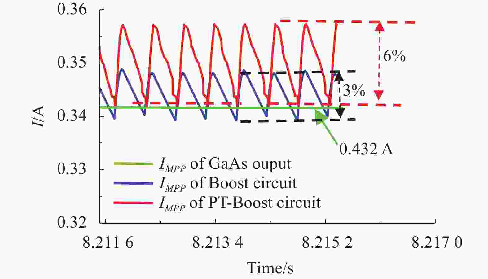
图 6 MPP 处的电流纹波
Figure 6. Current ripple at MPP
$$ \Delta {I_{MPP}} = \frac{{{I_{max }} - {I_{min }}}}{{{I_{avr}}}} $$ (19) 式中:Imax表示输入电流IMPP的最大值;Imin表示输入电流IMPP的最小值;Iavr表示输入电流的平均值。计算得到传统Boost电路在MPP处的输入电流纹波为6%,而PT-Boost电路MPP处的输入电流纹波为3%,PT-Boost电路的输入电流IMPP纹波减小了一半,且PT-Boost电路相比于传统的Boost电路在跟踪到MPP时的输入电流更接近GaAs电池的MPP处的电流。由此可知相比于传统Boost电路,利用PT-Boost电路作为DC/DC转换器时,其电流纹波更小。
-
为分析用于LWPT的DMPPT系统的可行性,设置了4块GaAs电池组成的电池阵列在温度为T=298 K,接收激光功率密度PL=0.3 W/cm2条件下,三种不同遮荫场景如表1所示。
表 1 不同遮荫情况下的4块4 cm×4 cm GaAs电池受到激光辐照的面积
Table 1. Area of laser light received by four 4 cm×4 cm GaAs PV under different shade conditions
Shade of array GaAs PV1/
cm2GaAs PV2/
cm2GaAs PV3/
cm2GaAs PV4/
cm20% 16 16 16 16 25% 16 16 8 8 50% 16 8 8 4 在上述的三种不同遮荫场景下,分别仿真了4块GaAs电池的输出特性曲线和DMPPT系统在工作时输出的最大功率,计算不同遮荫情况下DMPPT系统的整体效率,分析DMPPT系统降低阵列组串之间的电流失配问题的可能性。
GaAs电池阵列总的最大输出功率Pmax为各电池的最大输出功率之和,由图7(a)~(c)可计算出在遮荫度为0%、25%和50%时,GaAs电池阵列总的输出功率Pmax分别为7.145 W、5.322 W和3.964 W。DMPPT的最大输出功率Po为追踪到最大功率后的平均功率,其计算公式如下:
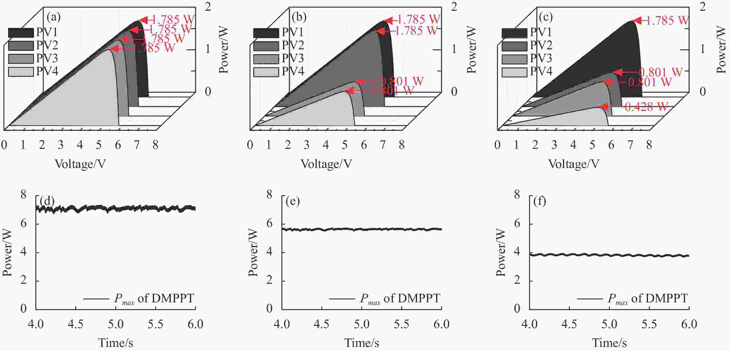
图 7 (a)、(b)和(c)分别为 0%、25%和 50%遮荫条件各 GaAs 电池 P-V 特性曲线;(d)、(e)和(f)分别为 0%、25%和 50%遮 荫条件下 DMPPT 系统最大输出功率
Figure 7. (a), (b) and (c) P-V characteristic curves and maximum power of each GaAs cell for 0%, 25%, and 50% shade conditions; (d), (e) and (f) DMPPT system output power under 0%, 25%, and 50% shading condition
$$ {P_o}{\text{ = }}\frac{{\int\limits_0^{\mathrm{T}} {p(t){\mathrm{d}}t} }}{T} = \frac{{\displaystyle\sum\limits_{{{i}} = 0}^N {{p_{oi}}} }}{N} $$ (20) 式中:T为采集DMPPT输出功率的时间;p(t)为DMPPT系统瞬时输出功率;Poi为示波器采集的DMPPT的瞬时功率数值;N为采集次数。根据上式得出,在遮荫度为0%、25%和50%时,DMPPT系统的输出最大功率Po分别为7.1 W、5.25 W和3.9 W。根据DMPPT系统整体效率η[24]:
$$ \eta = \frac{{{P_{max }}}}{{{P_o}}} $$ (21) 计算出在遮荫度为0%、25%和50%时,DMPPT系统的整体效率分别为99.3%、98.6%和98.3%。
通过仿真分析,GaAs电池阵列在不同的遮荫条件下,其DMPPT系统整体效率差值都在2%以内,可见利用DMPPT系统来降低激光无线能量传输过程中出现的瞄准误差、物体遮挡等因素造成GaAs电池阵列失配的问题是可行的。
-
为测试分析DMPPT系统的追踪效率和DMPPT系统整体效率,如图8所示,文中搭建了DMPPT系统效率试验,其中图8(a)为LWPT系统接收端与传输端,图8(b)为DMPPT系统测试实验装置。
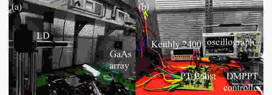
图 8 DMPPT 系统实验平台。(a) LWPT 系统接收端与传输端;(b) DMPPT 系统测试实验装置
Figure 8. Test system for DMPPT. (a) LWPT system receiver and transmitter; (b) DMPPT system test experiment device
-
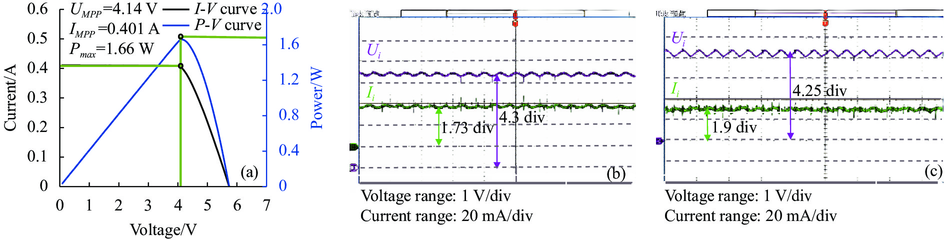
为了简化DMPPT的追踪效率测试实验,本小节仅搭建了传统Boost电路和PT-Boost电路分别作为DMPPT的子模块MPPT系统的DC/DC转换器,测试两种不同电路在子模块MPPT系统中的追踪效率即可。LD激光器发射激光,使GaAs电池所接收到的激光功率密度用GaAs电池的最佳功率Pmax为1.66 W,且MPP处的工作电压UMPP和电流IMPP分别为4.14 V和0.401 A。如图9(b)所示,利用Boost电路作为DC/DC转换器时,MPPT的输入电压Ui和电流Ii分别为4.3 V和0.346 A,且输入功率Pi为1.466 W,根据DMPPT系统的追踪效率公式[25]:
$$ \eta = \frac{{{P_{max }}}}{{{P_i}}} = \frac{{{U_{MPP}} \cdot {I_{MPP}}}}{{{U_i} \cdot {I_i}}} $$ (22) 得到追踪效率为89.9%;如图9(c)所示,采用PT-Boost电路作为DC/DC转换器时,MPPT的输入电压Uin和电流Iin分别为4.25 V和0.38 A,且输入功率Pi为1.615 W,得到追踪效率为93.5%。
根据以上分析可以得出结论,采用PT-Boost电路作为DC/DC转换器可以通过降低电流纹波来提升MPPT控制器的追踪效率,且追踪效率可以提升3.6%。
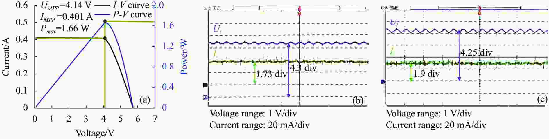
图 9 (a) GaAs电池I-V和P-V输出曲线;(b)、(c)分别为传统Boost和PT-Boost电路在MPP处时的工作电压及电流
Figure 9. (a) I-V and P-V output curve of GaAs cell; (b), (c) The operating voltage and current of the conventional Boost and PT- Boost circuits at the MPP are respectively
-
在进行DMPPT系统测试时,利用遮光板分别遮住GaAs电池阵列总面积的0%、25%和50%,模拟LWPT过程中,因瞄准系统误差、物体遮挡等原因造成的GaAs电池阵列接受到不均匀分布的激光辐照。下面将分析三种不同遮荫条件下,DMPPT系统正常工作时输出的功率以及DMPPT系统的整体效率。
DMPPT系统测试结果如图10所示,图10(a)、(b) 和(c)分别为遮光板对GaAs电池阵列遮挡0%、25%和50%时所得到的各电池的P-V输出曲线和最大功率。根据公式(20)计算出0%、25%和50%遮荫度时,各GaAs电池的最大功率之和分别为5.83 W、4.804 W和3.134 W。图10(d)、(e)和(f)分别为0%、25%和50%遮荫条件下DMPPT系统的输出功率,在T0时间范围内,DMPPT系统还未开始工作,DMPPT系统未能输出最大功率;在T1时间范围内,DMPPT系统开始工作,DMPPT控制器通过扰动观测算法来实时调整电池阵列输出电流与电压值,使DMPPT系统输出功率呈非线性逐步向最大功率点处附近扰动;在T2时间范围内,DMPPT系统寻找到最大功率点,且DMPPT系统输出功率在最大功率点附近趋于稳定,根据公式(20)计算出DMPPT系统的最大输出功率分别为5.43 W、4.45 W和2.83 W。根据公式(21)计算出,在遮荫度为0%时,DMPPT的整体电路效率为93%;在遮荫度为25%时,DMPPT的整体电路效率为92.6%;在遮荫度为50%时,DMPPT的整体电路效率为90.3%。文献[26]将传统Boost电路用作DMPPT系统的DC/DC转换器,分析了不同遮荫度情况下的DMPPT系统的整体效率,实验得到在遮荫度为0%时,DMPPT的整体效率为90.9%,在遮荫度为12.5%时,DMPPT的整体效率为90.8%,在遮荫度为35%时,DMPPT系统的整体效率为88.2%。
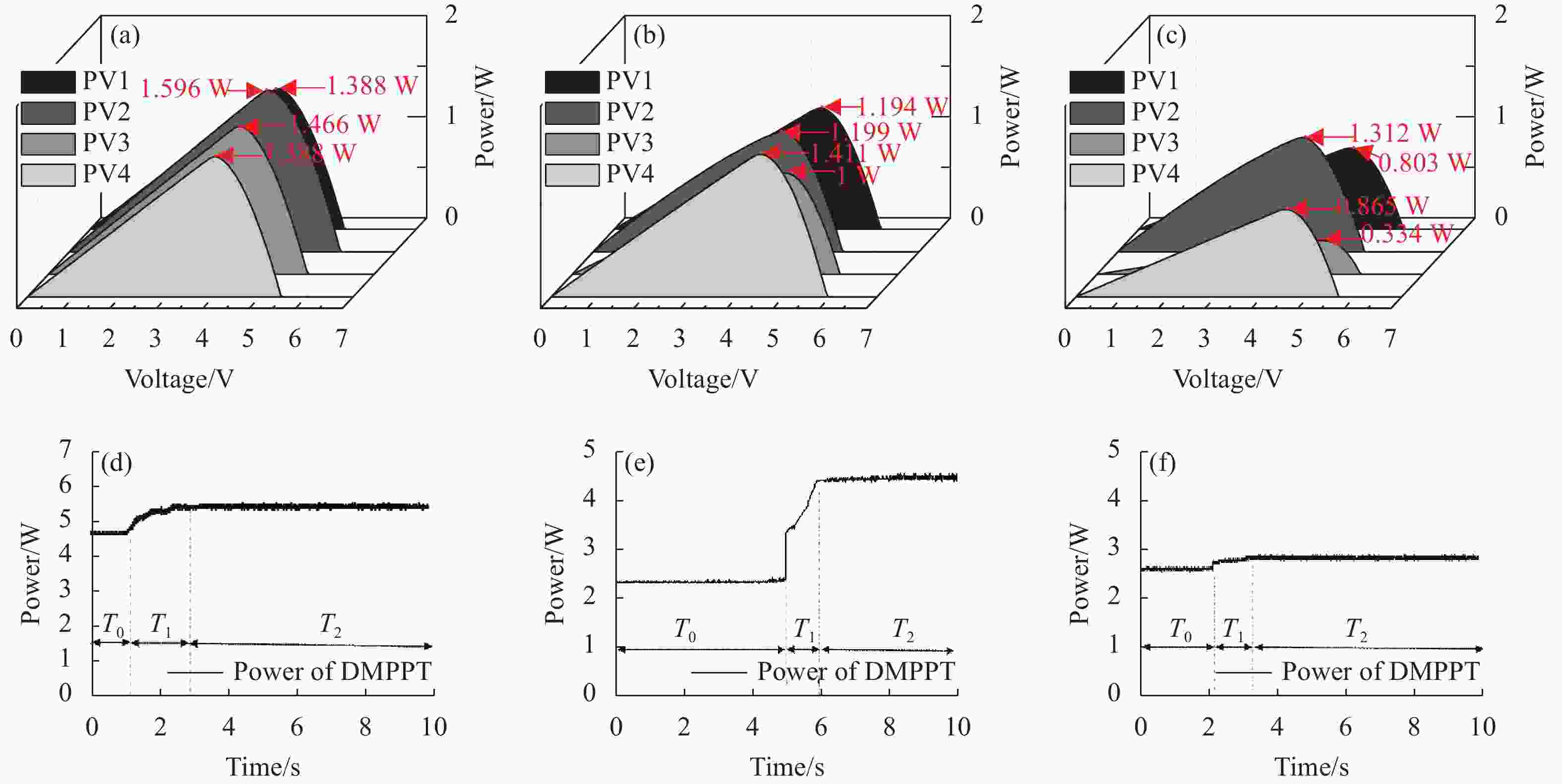
图 10 (a)、(b)和(c)分别为0%、25%和50%遮荫条件各GaAs电池P-V特性曲线及最大功率点功率;(d)、(e)和 (f) 分 别为0%、25%和50%遮荫条件下DMPPT系统输出功率
Figure 10. (a), (b) and (c) P-V characteristic curves and maximum power point power of each GaAs cell for 0%, 25%, and 50% shade conditions; (d), (e) and (f) DMPPT system output power under 0%, 25%, and 50% shade conditions
根据以上分析可以得出结论,采用PT-Boost电路作为DC/DC转换器,可以提升DMPPT的整体效率,且相比于将传统Boost电路作为DC/DC转换器的DMPPT系统,其整体效率有2%左右的提升。
-
在LWPT系统研究中,激光辐照分布不均匀导致光电池的输出呈现多峰现象且输出功率下降。文中采用DMPPT技术降低光电池阵列组串内电池间的电流失配,从而减小多峰情况的出现并提升输出功率。此外,利用PT-Boost电路替代传统Boost电路,通过并联分流改变支路电流之间的相位关系,减小输入电流的电流纹波,提升了电路追踪精度。仿真验证了不同激光无线能量传输场景下,DMPPT技术降低电池阵列组串间各电池输出电流失配的可行性。实验搭建了DMPPT测试系统,通过遮挡部分激光辐照模拟不同的遮荫场景,测试结果表明,DMPPT整体电路效率分别达到了93%、92.6%和90.3%。与采用传统Boost电路作为DMPPT系统的DC/DC转换器相比,采用PT-Boost电路作为DMPPT系统的DC/DC转换器,DMPPT系统在激光辐照不均匀场景下有着2%左右的提升。研究结果对激光辐照不均匀场景下激光无线能量传输的最大功率点追踪有指导意义。
Research on distributed maximum power point tracking system for laser wireless power transmission (inner cover paper)
-
摘要: 在激光无线能量传输中,由于瞄准系统误差和物体遮挡的影响,光电池阵列接收到的激光辐照分布不均匀,导致光电池阵列组串内的电池间出现电流失配,输出功率下降。针对该问题,采用分布式最大功率点追踪(Distributed Maximum Power Point Tracking, DMPPT)技术,减少光电池阵列组串内的电池间电流失配,并用并联型Boost(PT-Boost)电路替代传统Boost电路,降低DC/DC转换器的输入电流纹波,使DMPPT系统获得高追踪效率。实验结果表明,相较于传统Boost电路,PT-Boost电路的追踪效率提高3.6%,达到93.5%。在上述研究的基础上,设置了遮光率分别为0%、25%和50%的激光无线能量传输场景,DMPPT系统整体效率分别达到了93%、92.6%和90.3%。该研究结果对激光辐照不均匀场景下激光无线能量传输的最大功率点追踪指导意义。
-
关键词:
- 激光无线能量传输 /
- 分布式最大功率点 /
- 并联型Boost电路 /
- 追踪效率 /
- 整体效率
Abstract:Objective In Laser Wireless Power Transmission (LWPT) system, Maximum Power Point Tracking (MPPT) technology is a key factor to improve the power transfer efficiency by adjusting the circuit parameters at the receiver in real time, so that the output power of the laser photovoltaic cell reaches the maximum value. Due to the error of the aiming system and the obstruction of the object, the photovoltaic cell array will be subjected to uneven laser irradiation, and the photovoltaic cell array will generate different photogenerated currents, which leads to the current mismatch between the photovoltaic cells in the array, and the output power-volt characteristic curves is showing multi-peak, and the output power will be significantly reduced. The Distributed Maximum Power Point Tracking (DMPPT) technique can effectively reduce the current mismatch between the photovoltaic cells in the string of the array. Aiming at the problem of current mismatch in LWPT system, DMPPT technology is applied to LWPT system according to the characteristics of high laser irradiation power density but low power of Gallium Arsenide (GaAs) cell. It is proposed to replace the traditional Boost circuit with a Parallel-Type Boost circuit (PT-Boost) to reduce the input current ripple, so as to effectively improve the tracking accuracy of each MPPT submodule of DMPPT system and the overall circuit efficiency of DMPPT. Methods The working state of PT-Boost circuit is theoretically analyzed (Fig.5). A theoretical model of the DMPPT system is established and its output characteristice is analyzed; The above theoretical model is used to build a set of DMPPT simulation system, simulate and analyze the input current ripples of the PT-Boost circuit relative to the Boost circuit in the MPPT sub-module of the DMPPT system, and set up different LWPT scenarios to verify the feasibility of the DMPPT system. Finally, the DMPPT experimental platform (Fig.8) is built to test the specific performance of the DMPPT system. Results and Discussions The simulation results show that under the same GaAs cell model parameters, the current ripple is reduced and the MPPT accuracy is higher when utilizing the PT-Boost circuit as a DC/DC converter compared to the traditional Boost circuit (Fig.6). And under different shading conditions, the difference between the maximum power point of the DMPPT output and the total power of the GaAs battery array is within 2%(Fig.7). which shows that it is feasible to utilize the DMPPT system to reduce the current mismatch of each cell among the strings of the GaAs battery array. A DMPPT test system was established, and the experimental results showed that the tracking efficiency of the DMPPT system based on the PT-Boost circuit was improved by 3.6% to 93.5% compared with the traditional Boost circuit (Fig.9). Based on the above study, laser wirelessenergy transmission scenarios with 0%, 25% and 50% shading were set up, and the overall circuit efficiency of DMPPT reached 93%, 92.6% and 90.3%, respectively (Fig.10). Conclusions In the study of LWPT system, the non-uniform distribution of laser irradiation leads to the occurrence of multi-peak conditions in the output of photovoltaic cells array, and the output power decreases. In this paper, The DMPPT system is used to reduce the current mismatch between cells in the photovoltaic cell array string, thus reducing the occurrence of multi-peak conditions and improving the output power. In addition, the PT-Boost circuit is utilized to replace the traditional Boost circuit and the phase relationship between the branch currents is changed by shunting in parallel, which reduces the current ripple of the input current of circuit and effectively improves the tracking accuracy of the DMPPT. The simulation verifies the feasibility of the DMPPT system to reduce the output current mismatch of each cell between battery array strings under different laser wireless energy transfer scenarios. The DMPPT test system was built, which simulates different shading scenarios by blocking part of with the sunshade. The test results show that the overall circuit efficiency of the DMPPT reaches 93%, 92.6% and 90.3%, respectively. Compared with using a traditional Boost circuit as the DC/DC converter of the DMPPT system, the DMPPT system has an improvement of about 2% in the laser irradiation non-uniformity scenario by using a PT-Boost circuit as the DC/DC converter of the DMPPT system. The results are instructive for the maximum power point tracking of laser wireless power transmission under uneven laser irradiation scenarios. -
图 3 光电池输出特性。(a) I-V曲线;(b) P-V曲线
Figure 3. PV cell output characteristics. (a) I-V curve; (b) P-V curve
图 5 PT-Boost 电路的六种工作状态模式。(a)状态 1; (b)状态 2; (c)状态 3; (d)状态 4; (e)状态 5; (f)状态 6
Figure 5. Equivalent circuit diagrams of PT-Boost for six operating states. (a) S1; (b) S2; (c) S3; (d) S4; (e) S5; (f) S6
图 7 (a)、(b)和(c)分别为 0%、25%和 50%遮荫条件各 GaAs 电池 P-V 特性曲线;(d)、(e)和(f)分别为 0%、25%和 50%遮 荫条件下 DMPPT 系统最大输出功率
Figure 7. (a), (b) and (c) P-V characteristic curves and maximum power of each GaAs cell for 0%, 25%, and 50% shade conditions; (d), (e) and (f) DMPPT system output power under 0%, 25%, and 50% shading condition
图 8 DMPPT 系统实验平台。(a) LWPT 系统接收端与传输端;(b) DMPPT 系统测试实验装置
Figure 8. Test system for DMPPT. (a) LWPT system receiver and transmitter; (b) DMPPT system test experiment device
图 9 (a) GaAs电池I-V和P-V输出曲线;(b)、(c)分别为传统Boost和PT-Boost电路在MPP处时的工作电压及电流
Figure 9. (a) I-V and P-V output curve of GaAs cell; (b), (c) The operating voltage and current of the conventional Boost and PT- Boost circuits at the MPP are respectively
图 10 (a)、(b)和(c)分别为0%、25%和50%遮荫条件各GaAs电池P-V特性曲线及最大功率点功率;(d)、(e)和 (f) 分 别为0%、25%和50%遮荫条件下DMPPT系统输出功率
Figure 10. (a), (b) and (c) P-V characteristic curves and maximum power point power of each GaAs cell for 0%, 25%, and 50% shade conditions; (d), (e) and (f) DMPPT system output power under 0%, 25%, and 50% shade conditions
表 1 不同遮荫情况下的4块4 cm×4 cm GaAs电池受到激光辐照的面积
Table 1. Area of laser light received by four 4 cm×4 cm GaAs PV under different shade conditions
Shade of array GaAs PV1/
cm2GaAs PV2/
cm2GaAs PV3/
cm2GaAs PV4/
cm20% 16 16 16 16 25% 16 16 8 8 50% 16 8 8 4  下载: 导出CSV
-
[1] Zhao Changming, Wang Yunshi, Guo Ludeng, et al. Development of laser wireless power transmission technology [J]. Laser Technology, 2020, 44(5): 538-545. (in Chinese) doi: 10.7510/jgjs.issn.1001-3806.2020.05.003 [2] Jin K, Zhou W. Wireless laser power transmission: A review of recent progress [J]. IEEE Transactions on Power Electronics, 2018, 34(4): 3842-3859. doi: 10.1109/TPEL.2018.2853156 [3] Liu Xiaoguang, Hua Wenshen, Liu Xun, et al. Methods to improve efficiency of photovoltaic receiver for laser powered unmanned aerial vehicle [J]. Infrared and Laser Engineering, 2016, 45(3): 101-105. (in Chinese) doi: 10.3788/IRLA201645.0306002 [4] Barask A, Hongru C, YoshimuraY, et al. Energy orbit-laser power transmission to satellites using small space solar power satellite constellation [J]. Space Solar Power Systems, 2022, 7: 12-17. doi: 10.24662/sspss.7.0_12 [5] Sun Zhiyu, Lu Jian, Zhang Hongchao, et al. Performance test of solar cell under laser energy transmission and signal transmission [J]. Infrared and Laser Engineering, 2022, 51(2): 20210888. (in Chinese) doi: 10.3788/IRLA20210888 [6] Yang Qingdong, Yang Huomu, Wang Jun, et al. MPPT integrated simulation system for laser wireless power transmission [J]. Infrared and Laser Engineering, 2022, 51(5): 20210522. (in Chinese) doi: 10.3788/IRLA20210522 [7] Assaf B, Joseph A. Performance analysis of concentrator photovoltaic dense-arrays under non-uniform irradiance [J]. Solar Energy Materials and Solar Cells, 2013, 117: 110-119. doi: 10.1016/j.solmat.2013.04.029 [8] Debashisha J, Vanjari V. Modeling of photovoltaic system for uniform and non-uniform irradiance: A critical review [J]. Renewable and Sustainable Energy Reviews, 2015, 52: 400-417. doi: 10.1016/j.rser.2015.07.079 [9] Wu Zhengnan, Xie Jiangrong, Yang Yannan. Effect of light intensity uniformity on the photoelectric conversion efficiency of GaAs cells [J]. Infrared and Laser Engineering, 2017, 46(6): 0606001. (in Chinese) doi: 10.3788/IRLA201746.0606001 [10] Yuan Jianhua, Wang Lin, Zhao Ziwei, et al. MPPT technology of laser powered UAVbased on improved bat algorithm [J]. Laser & Infrared, 2022, 52(6): 814-819. (in Chinese) doi: 10.3969/j.issn.1001-5078.2022.06.004 [11] Tey K S, Mekhilef S, Seyedmahmoudian M, et al. Improved differential evolution-based MPPT algorithm using SEPIC for PV systems under partial shading conditions and load variation [J]. IEEE Transactions on Industrial Informatics, 2018, 14(10): 4322-4333. doi: 10.1109/TII.2018.2793210 [12] Başoğlu M E. Comprehensive review on distributed maximum power point tracking: Submodule level and module level MPPT strategies [J]. Solar Energy, 2022, 241: 85-108. doi: 10.1016/j.solener.2022.05.039 [13] Mohapatra A, Nayak B, Das P, et al. A review on MPPT techniques of PV system under partial shading condition [J]. Renewable and Sustainable Energy Reviews, 2017, 80: 854-867. doi: 10.1016/j.rser.2017.05.083 [14] Aniruddha K M, Jayanta B, Anjana K G, et al. A simple real-time DMPPT algorithm for PV systems operating under mismatch conditions [J]. Journal of Power Electronics, 2018, 18(3): 826-840. doi: 10.6113/JPE.2018.18.3.826 [15] Jeyaprabha S B. Distributed maximum power point tracking for mismatched modules of photovoltaic array[M]//Advanced Technologies for Solar Photovoltaics Energy Systems. Cham: Springer International Publishing, 2021. [16] Mao M, Zhang L, Duan P, et al. Grid-connected modular PV-converter system with shuffled frog leaping algorithm based DMPPT controller [J]. Energy, 2018, 143: 181-190. doi: 10.1016/j.energy.2017.10.099 [17] Yuan J, Zhao Z, Liu Y, et al. DMPPT control of photovoltaic microgrid based on improved sparrow search algorithm [J]. IEEE Access, 2021, 9: 16623-16629. doi: 10.1109/ACCESS.2021.3052960 [18] Chu G, Wen H, Jiang L, et al. Bidirectional flyback based isolated-port submodule differential power processing optimizer for photovoltaic applications [J]. Solar Energy, 2017, 158: 929-940. doi: 10.1016/j.solener.2017.10.053 [19] Zhu T, Wang F, Shi S, et al. Optimization of time-sharing output Maximum Current Tracking (MCT) strategy in subpanel level Distributed Maximum Power Point Tracking (DMPPT) application[C]//2016 IEEE 8th International Power Electronics and Motion Control Conference (IPEMC-ECCE Asia), 2016: 3435-3440. [20] Chattopadhyay R, Bhattacharya S, Foureaux N C, et al. Low-voltage PV power integration into medium voltage grid using high-voltage SiC devices [J]. IEEJ Journal of Industry Applications, 2015, 4(6): 767-775. doi: 10.1541/ieejjia.4.767 [21] Diab-Marzouk A, Trescases O. SiC-based bidirectional cuk converter with differential power processing and MPPT for a solar powered aircraft [J]. Transportation Electrification IEEE Transactions on, 2015, 1(4): 369-381. doi: 10.1109/TTE.2015.2505302 [22] Sohn S M, Choi I S, Lim S I, et al. ASIC design of DMPPT control for photovoltaic systems[C]//2013 International SoC Design Conference (ISOCC), IEEE, 2013: 76-79. [23] Jiang Y, Qahouq J A A. Single-sensor multi-channel maximum power point tracking controller for photovoltaic solar systems [J]. IET Power Electronics, 2012, 5(8): 1581-1592. doi: 10.1049/iet-pel.2012.0157 [24] Zhu T, He X, Guan T, et al. An integrated single inductor-single sensor based photovoltaic optimizer with an optimal current point tracking strategy[C]//2017 IEEE Energy Conversion Congress and Exposition (ECCE), 2017: 2301-2304 [25] Debdouche N, Zarour L, Chebabhi A, et al. Genetic algorithm-super-twisting technique for grid-connected PV system associate with filter [J]. Energy Reports, 2023, 10: 4231-4252. doi: 10.1016/j.egyr.2023.10.074 [26] 常佳杰. 可扩展的模块化微纳卫星电源系统的研究与设计[D]. 南京: 南京航空航天大学, 2020. -

 点击查看大图

计量
- 文章访问数: 16
- HTML全文浏览量: 2
- PDF下载量: 5
- 被引次数: 0

