


-
随着低空空域的逐渐开放以及无人机(UAV)等“低慢小”飞行器技术的快速发展,无人机不仅在军事领域中发挥出了重要作用,在民用领域也得到了广泛的应用[1−5]。然而,无人机给人们生产生活带来便利的同时,其“黑飞”、违规非法使用和滥用对国家安全和公共安全造成了严重威胁[6]。尤其是无人机在军用空袭作战中的使用将对军事行动产生很大的影响。因此,在军民领域针对无人机等“低慢小”飞行器的防御和打击具有强烈需求[7−8]。激光武器的迅速发展,使其在低空防御和无人机打击方面表现了出巨大的优势和潜力[9−12]。
高能激光因其高精确性、强抗电磁干扰能力以及高速打击等一系列优势[13],已逐渐迈向实用阶段,尤其将在低空防御和打击低慢小目标中得到有效应用[14]。相较于传统的动能炮弹拦截,高能激光具有打击速度快、作战效费比高、可持续作战、效果可控、破坏范围小等优势。但由于高能激光无法像炮弹一样直接毁伤目标,其对目标的毁伤打击需要满足以下两个条件:足够的毁伤功率密度、持续稳定的辐照和足够的辐照时间。一般来说,在高能激光的辐照下,目标很容易发生燃烧起火现象,导致目标本体被火焰和烟雾部分或全部遮挡,这无疑对高能激光的探测与跟瞄系统造成了极大干扰。因此,当前的迫切需求就是要求在火光和烟雾等干扰条件下,探测与跟瞄系统能够保持对移动飞行目标的有效探测和稳定的探测跟踪。
为使高能激光持续且稳定地辐照于目标表面,需保证目标识别与跟踪系统准确地瞄准目标上的特征位置。由于在目标被高能激光持续照射期间,探测系统必须一直保持较高的探测精度,因此这也对跟踪系统提出了极高的要求。采用传统被动的可见光和红外探测方式,极其容易受火光烟雾的剧烈干扰,导致探测系统对目标成像质量差,甚至发生无法探测到目标的情况,难以实现高能激光毁伤过程中的稳定跟踪和瞄准需求。值得庆幸的是,激光成像雷达对目标成像的分辨率较高,且由于距离像是主动激光在实体物体上反射的回波信号所成,因此是一种更为有效的不受火光和烟雾等干扰影响的目标本体探测新方法[15−17]。综上所述,文中针对火光和烟雾等条件下传统可见光和红外探测方式对目标跟踪和瞄准易受影响导致失跟的问题,提出了基于主动激光雷达体制的目标本体探测和瞄准新方法,并通过实验验证在该条件下无人机激光距离像探测和跟踪的可行性和有效性。
-
文中以无人机作为目标,无人机的机翼一般为聚丙烯(Polyp-ropylene, PP),起落架一般是聚酰胺(Polyamide, PA)。机身传统上一般采用是聚碳酸酯(Polycarbonate, PC)。此类高分子聚合物在不充分燃烧时会产生黑烟,其燃烧充分时的火焰呈淡黄色,温度约为1100 ℃。
近似使用黑体辐射定律描述火焰的辐射特性。其公式定义为:
$$ {M_\lambda } = \frac{{2\pi h{c^2}{\lambda ^{ - 5}}}}{{{{\rm{e}}^{{{hc} \mathord{\left/ {\vphantom {{hc} {\lambda kT}}} \right. } {\lambda kT}}}} - 1}} $$ (1) 式中:${M_\lambda }$为单位波长的辐出度;c为真空光速;h为普朗克常数;k为玻尔兹曼常数;T为绝对温度。
分析温度对1064 nm波长光辐出度的影响,火光温度为1373 K时,得到火光辐出度在1.4 W/cm2。
由公式(1)可得火光辐出度$M$为:
$$ M = \int_{{\lambda _1}}^{{\lambda _2}} {\frac{{2\pi {{h}}{{{c}}^2}}}{{\exp ({{hc} \mathord{\left/ {\vphantom {{hc} {\lambda kT}}} \right. } {\lambda kT}}) - 1}}} \times \frac{1}{{{\lambda ^5}}}{\mathrm{d}}\lambda $$ (2) 1064 nm处在10 nm窄带滤光片通带内火光的辐出度$M = \Delta \lambda \times {M_\lambda } = 0.014$ W/cm2。
-
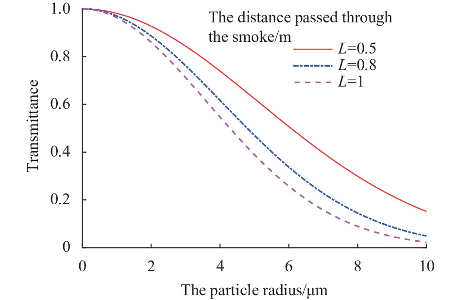
根据Mie散射理论及Lambert-Beer定律可知烟雾对激光的透过率可描述为:
$$ T = {{\rm{e}}^{ - nkL}} $$ (3) 式中:n为烟雾浓度;L为光在烟雾中传输距离;k为烟雾的质量消光系数。
PP、PC高分子聚合物燃烧产物主要成分为碳黑,碳黑复折射率${n_r}$为1.6~2.0、${n_i}$为0.3~0.8。粒径范围为0.2~5 μm。
分析不同烟雾浓度及不同传输距离对激光的穿透率的影响。图1为激光在烟雾中传输距离为1 m,在浓度为2、4、6 g/mm3透过率随半径的变化曲线。

图 1 不同浓度透过率变化曲线
Figure 1. Transmittance variations at different concentrations
图2为烟雾浓度为6 g/mm3,改变激光在烟雾中传输距离时透过率随半径的变化曲线。
图 2 不同穿透距离透过率变化曲线
Figure 2. Transmittance changes at different penetration distances
通过微粒分布函数得到,粒径分布在2~4 μm。结合图1与图2结果,综合烟雾浓度仿真,假设激光透过烟雾的长度小于1 m,获得激光在烟雾中透过率范围为60%~85%。
-
构建Torrance-Sparrow双向反射分布函数${f_r}$模型。经查阅材料,PP、PA、PC粗糙度参数值范围为0.1、0.2、0.4、0.8、1.6 μm。
在后向散射情况下$ \varphi {\text{ = }}{180^\circ } $,分析粗糙程度$\sigma $对${f_r}$值的影响。
设置$ \varphi {\text{ = }}{180^\circ } $,在观测角${\theta _r} = {30^ \circ }$,${\theta _r} = {60^ \circ }$时观察${f_r}$的值随入射角${\theta _i}$的变化规律,得到图3所示曲线。对比图3(a)和(b)可以发现,观测角的增大会增加${f_r}$中的漫反射分量,削弱镜面反射的作用,在相同粗糙程度下可增大${f_r}$值。对于后向散射情况,当粗糙度大于0.2 μm时,同一粗糙程度下的${f_r}$较平缓,在${f_r}$的较小区间内变化。因此在0.2~0.8 μm粗糙范围得到双向反射分布函数${f_r}$取值区间为0.2~8。

图 3 双向反射分布函数随入射角的变化规律。(a) ${\theta _r} = {30^ \circ }$时${f_r}$随${\theta _i}$变化曲线;(b) ${\theta _r} = {60^ \circ }$时${f_r}$随${\theta _i}$变化曲线
Figure 3. Variations of bidirectional reflection distribution function with incident angle. (a) curves of ${f_r}$ changing with ${\theta _i}$ at ${\theta _r} = {30^ \circ }$; (b) curves of ${f_r}$ changing with ${\theta _i}$ at ${\theta _r} = {60^ \circ }$
基于获得的火光光学特性、激光在烟雾中衰减特性以及无人机机身材料的激光散射特性影响因素理论分析结果,可为下文激光雷达距离像探测系统的设计提供科学的参数选择依据。
-
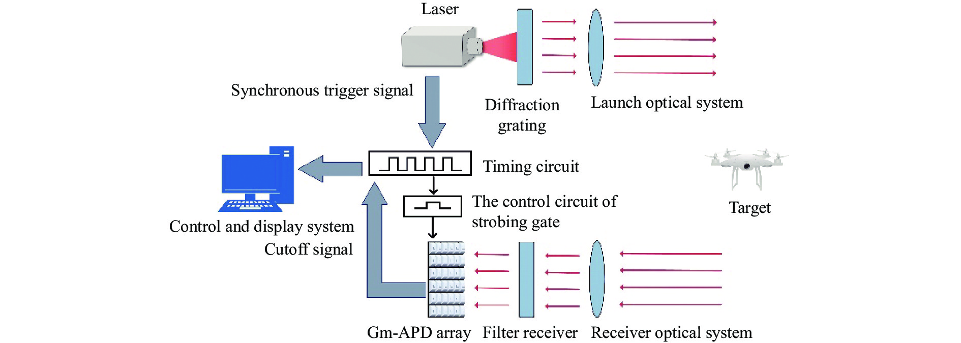
设计了APD激光雷达探测系统,如图4所示。该系统采用SPAD(Single Photon Avalanche Diode)作为探测器,脉冲激光雷达波长为1064 nm,主要包括四部分:激光光源、接收光学系统,Gm-APD探测模块和显示与控制系统。
图 4 APD激光雷达系统结构图
Figure 4. Structure diagram of APD lidar system
在激光雷达探测系统中,点目标的激光雷达方程为:
$$ {P_{{r}}} = \frac{{4{P_t}\rho {A_{{o}}}{A_r}{\eta _t}{\eta _r}\eta _{atm}^2}}{{{\pi ^2}\theta _t^2{R^4}}} $$ (4) 式中:${P_{{r}}}$为激光雷达接收目标回波功率;${P_t}$为系统发射功率;$ \rho $为目标平均反射率;$ {A_o} $为激光照射的目标面积;$ {\theta _{\text{t}}} $激光雷达发射光束的发散角;$ {A_r} $为探测器有效接收面积;${\eta _{{t}}}$为发射系统效率;$ {\eta _r} $为接收系统效率;${\eta _{{{atm}}}}$为大气单程透过率;$ R $为探测器到目标的距离。
照射到目标表面并经目标表面后向散射后的探测器接收的回波平均信号光子数为:
$$ {N'_s} = \frac{{{P_r}\tau }}{{h\nu }} = \frac{{4{P_t}\tau \rho {A_{{o}}}{A_r}{\eta _t}{\eta _r}\eta _{atm}^2}}{{{\pi ^2}\theta _t^2{R^4}h\nu }}\cos \theta $$ (5) 式中:$\theta $为目标表面法线与光束的夹角;τ为激光脉冲宽度。
由于探测器接收的背景光包括太阳光以及目标燃烧时产生的火光,因此平均背景噪声光子数${N'_b}$可表示为:
$$ {N'_b} = {N_{fire}} + {N_{sun}} + {N_{sunr}} $$ (6) 式中:${N_{fire}}$为入射到接收系统的火光平均光子数;${N_{sun}}$为直接入射到接收系统的太阳辐射光子数;${N_{sunr}}$为经目标反射的太阳辐射光子数。
入射到探测器光敏面所有光子所产生的光电子数为:${\eta _q}({N'_s} + {N'_b})$。由于探测器本身在没有入射光时也会产生光电子,这是器件本身所存在着暗电流噪声引起的,暗电流噪声电子数${N_{{d}}}$一般认为是均匀分布的。因此探测器的平均光电子数总数为:
$$ \begin{gathered} {N_{sn}} = {\eta _q}({{N'}_s} + {{N'}_b}) + {N_d} = {N_s} + {N_b} + {N_d} \\ \end{gathered} $$ (7) 式中:${N_{{s}}}$为平均信号光电子数;${N_{{b}}}$为平均背景噪声光电子数。
由于激光雷达对目标成距离像时是通过对多次脉冲的回波信号累积而得到的,因此在光子积累成像过程中,若目标信号分布在第${T_1}\sim{T_j}$个区间,则在目标在探测第i个区间前就有${{d = {t_d}} \mathord{\left/ {\vphantom {{d = {t_d}} {\Delta t}}} \right. } {\Delta t}}$个时间间隔,其中${t_d}$为目标相对距离门开启的时间。
通过分析可得到${T_1}\sim {T_j}$目标区间内探测器的触发概率为$ \displaystyle\sum\limits_{i = {T_1}}^{{T_j}} {{P_j}} (i) $,令$ P=\displaystyle\sum_{i=T_{i}}^{T_{j}} P_{j}(i) $,其变化范围为0~1,则虚警概率为:
$$ {P_{{f}}} = 1 - P - \exp ( - {N_{sn}}) $$ (8) 目标表面的反射率$\rho $与双向反射分布函数${f_{_r}}$的关系可表示为:
$$ \rho = \frac{{{f_r}}}{\pi }\cos {\theta _i} $$ (9) 根据激光在大气中的透过率可知在能见度为中等时,计算得到1064 nm波长激光的衰减系数为0.1658 km−1。
根据前文分析结果和器件参数进行仿真,仿真所用参数如表1所示。
表 1 仿真参数
Table 1. Simulation parameters
Parameter Value Laser wavelength ($\lambda $)/nm 1064 Laser divergence angle (${\theta _{{t} } }$)/mrad 10 Launch system efficiency (${\eta _{{t} } }$) 0.9 Receiving system efficiency ($ {\eta _r} $) 0.9 Effective receiving area of the detector ($ {A_r} $)/cm2 30 Atmospheric one-way transmittance (${\eta _{ {{atm} } } }$) 0.993 Filter bandwidth ($\Delta \lambda $)/nm 10 Dark counting rate (${N_d}$)/kHz 15-30 Target average reflectivity ($ \rho $) 0.3 The distance of the target (R)/m 30 Quantum efficiency of detector ($ {\eta _q} $) 20% $ \Delta t $/ns 1 d 30 根据实际数据计算,设置第${T_j} - {T_1}$为10 ns,$ {t_d} = d \cdot \Delta t $为30 ns,暗计数率为20 kHz,总背景噪声约为8200 kHz,仿真可得到探测概率与虚警概率随激光脉冲能量的变化规律。可知当激光能量大于4 mJ时,每增加1 mJ能量,探测概率增加不到1%。考虑实验实际情况,取激光脉冲能量的较合适范围为0.75~4 mJ。
在上述探测器参数下只改变目标距离,通过仿真可知当目标距离探测器约500 m时,能探测到目标所需的最小脉冲能量约为1.16 mJ;当目标距离探测器约1 000 m时,能探测到目标所需的最小脉冲能量约为13 mJ。由于探测器探测目标时将受到多种因素的影响,如天气的好坏、激光功率、探测器的稳定性和量子效率、有效接收面积和系统效率等的限制,因此在数公里范围外的目标,对激光器能量要求较高,而大孔径光学系统将进一步降低激光器的能量要求。
-
Mean-Shift算法是图像跟踪领域的经典算法,其总体流程图如图5所示。
图 5 Mean-Shift图像跟踪流程图
Figure 5. Mean-Shift image tracking flowchart
对基于距离像的目标跟踪的实现过程为:首先,用某颜色特征表示跟踪目标,对目标模型进行描述;其次,通过在距离像上手动框选包含目标的区域,初始化物体的位置和大小,确定搜索窗口大小并计算目标模型的概率密度;然后,将上一步计算得到的目标位置定义为中心,在当前的候选区域内计算得到目标的质心坐标,同时计算直方图,获得候选区域的概率密度;最后,计算当前区域内中各点的权重,比较目标模型与候选区模型的相似度,把相似函数最大的候选区域作为目标位置,然后再利用该位置重新定义中心,计算目标的新位置反复迭代,从而实现目标跟踪。
-
基于前文所设计的激光雷达探测系统以及研究结果,搭建了激光雷达探测实验系统,并设定激光器以及探测器的参数,使其正常工作。
文中所用探测器为APD探测相机,包括SPAD单光子探测器和光学镜头。其中ADP参数如表2所示,光学镜头参数如表3所示。
表 2 APD探测器参数
Table 2. The APD detector parameters
APD detector parameters Minimum values Typical values Maximum values Pixel spacing/μm − 50 − Working wavelength/nm 950 − 1650 Time resolution/ns 1 − − Frame rate/kHz − − 25 Working voltage/V DC10 DC12 DC13 Operating temperature/℃ − −20 − Dark counting rate − 15% 30% Quantum efficiency of detector − 20% − 表 3 光学镜头参数
Table 3. Optical lens parameters
Optical lens parameters Typical values Receiving efficiency 90% Receiving area/cm2 30 Effective pixel rate 98% 实验中,目标与激光雷达系统距离约为30 m。为滤除噪声光子的影响,获得较为清晰的目标距离像,需合理设置系统的选通时间。通过理论分析,在20~180 ns范围内以10 ns为间隔逐步改变选通时间后发现,在90~110 ns范围内所探测到的目标图像清晰度较高,通过实验验证发现选通延时在100 ns处对应的探测图像最清晰。因此设置系统选通时间为100 ns,这其中包括了目标前后15 m的距离所对应的选通时间。假设激光器发射脉冲时刻为0 s时刻,经计算确定探测器打开时刻为50 ns,探测器关闭时刻为150 ns,则目标探测器接收光子时间约为范围50~150 ns。因此,在该范围内可以较好保证接收到大部分的信号光子,减小噪声光子影响从而获得较清晰的目标距离像。
实验中,动态无人机的模拟是通过悬挂无人机并控制挂绳使其做水平运动来实现的。
通过搭建的激光雷达系统对正常背景下运动的无人机进行距离图像序列采集,采用Mean-Shift跟踪算法对获得的图像序列进行跟踪,得到了如图6 (a)所示的跟踪曲线;以视频帧数作为z轴,得到目标中心点三维轨迹曲线图如图6 (b)所示。
图 6 距离像跟踪获得的无人机轨迹结果。 (a) 运动轨迹图像;(b) 目标中心轨迹曲线
Figure 6. UAV trajectory by range profile tracking. (a) Motion trajectory image; (b) Target center trajectory curve
对相同条件下的可见光图像序列进行跟踪处理,可得到如图7(a)和(b)所示的跟踪曲线。
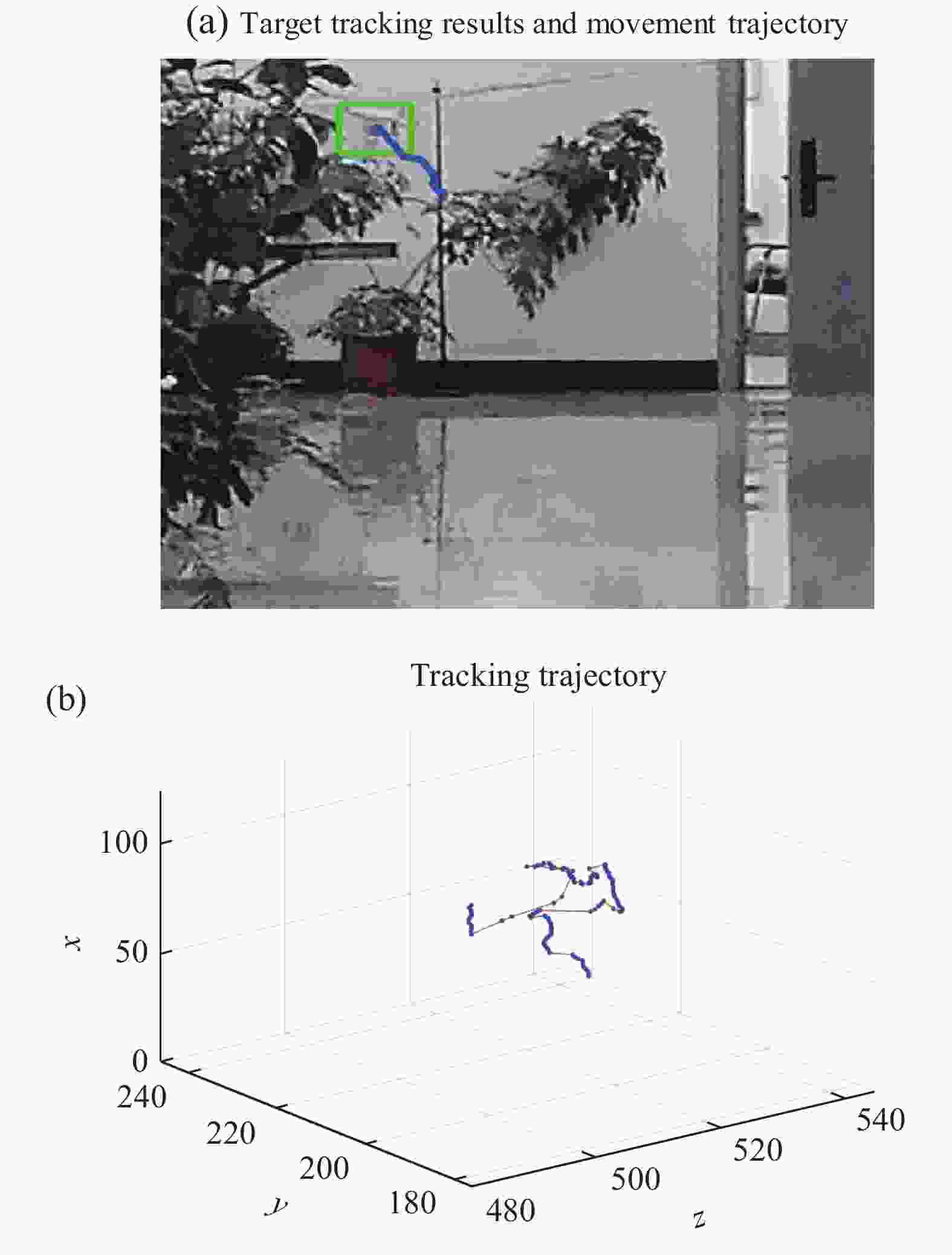
图 7 可见光跟踪无人机轨迹。 (a) 运动轨迹图像;(b) 目标中心轨迹曲线
Figure 7. UAV trajectory by visible light tracking. (a) Motion trajectory image; (b) Target center trajectory curve
从图6(a)、图7(a)图像跟踪轨迹可知,目标的跟踪轨迹大致相同,但由于探测器的成像过程以及可见光图像序列与距离像序列的帧数的差异造成了图6(b)、图7(b)图曲线出现较大差异。为进行误差定量分析,考虑到帧速率的差异,文中以距离像序列跟踪目标帧数为基准,通过约29.25/10的帧间隔提取对应可见光图像序列帧的跟踪目标中心位置数据进行误差分析对比。
以视频帧数作为x轴,目标质心作为y轴,分别绘制可见光图像序列和距离像序列目标质心的X、Y轴坐标随帧数的变化曲线。归一化得到了基于可见光和距离像跟踪方法获得的目标质心坐标的X坐标轨迹图与Y坐标轨迹图,分别如图8(a)、(c)所示。由此可知,基于可见光图像跟踪与距离像跟踪的目标质心X、Y坐标轨迹曲线基本一致,通过计算基于距离像跟踪的目标质心位置相对可见光跟踪的目标质心位置的角弧度差大小,得到了X坐标角弧度曲线和Y坐标角弧度曲线,分别如图8(b)和(d)所示。可知X坐标的平均角弧度约为0.55 mrad,Y坐标的平均角弧度为0.53 mrad,即基于距离像跟踪的目标质心位置相对基于可见光图像跟踪结果的角偏差小于0.55 mrad。这一结果在误差允许范围内,因此基于距离像序列的跟踪结果与基于可见光图像序列的跟踪结果基本符合,证明了Mean-Shift跟踪算法可用于距离像的跟踪。
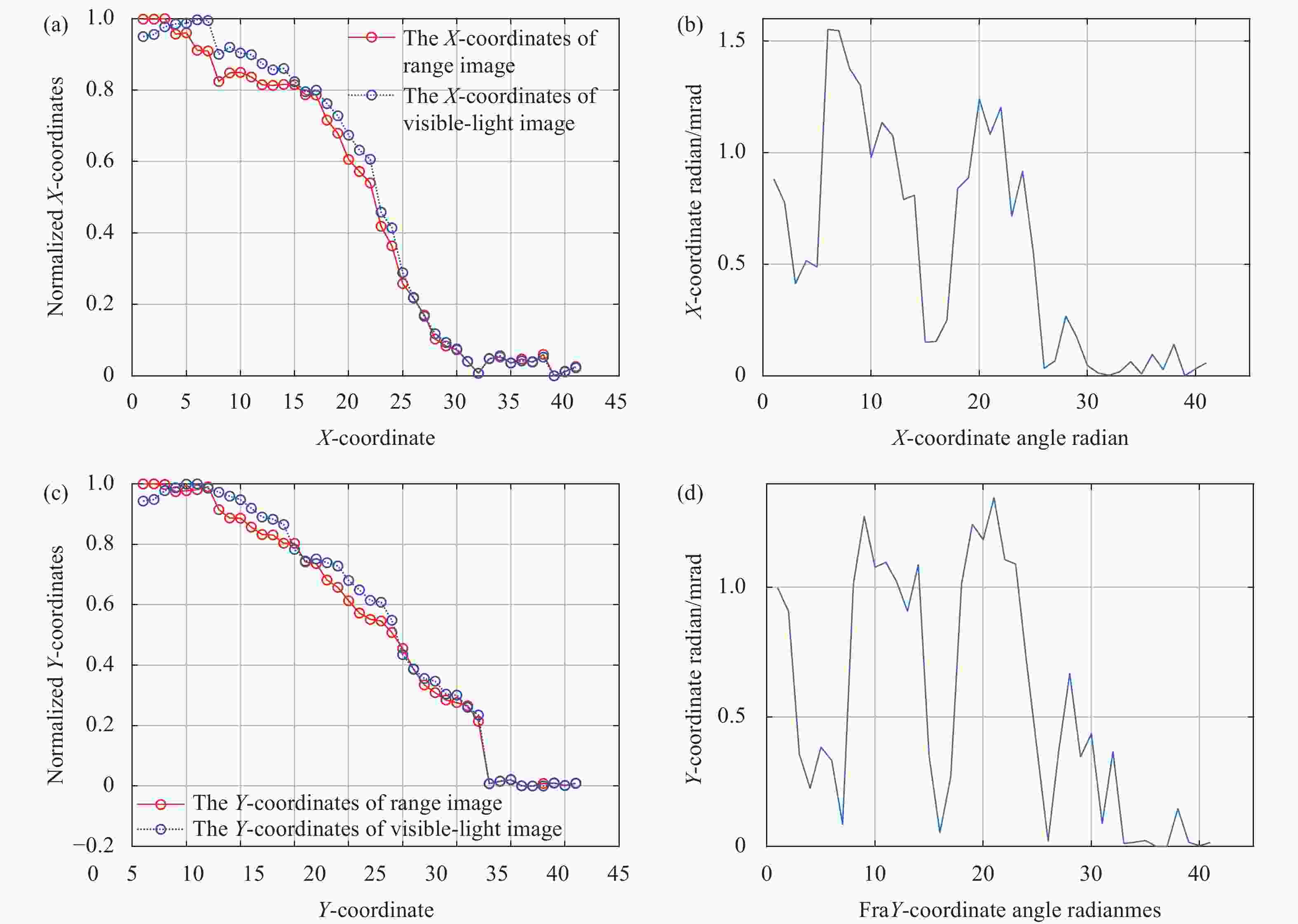
图 8 距离像跟踪和可见光跟踪效果对比。 (a) X坐标轨迹; (b) X坐标角弧度曲线;(c) Y坐标轨迹; (d) Y坐标角弧度曲线
Figure 8. Comparison of range profile tracking and visible light tracking. (a) X-coordinate trajectory; (b) X-coordinate angle radian curve; (c) Y-coordinate trajectory; (d) Y-coordinate angle radian curve
-
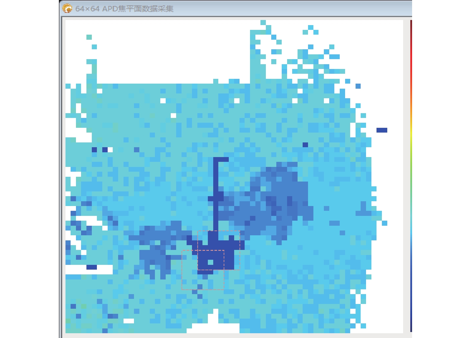
在室内通过加湿器模拟目标被高能激光照射时的烟雾遮挡成像实验。选通延时为0 ns时采集图像如图9所示,通过雷达系统采集烟雾遮挡下的距离像,可看到目标被烟雾所遮挡,无法得到无人机的图像。
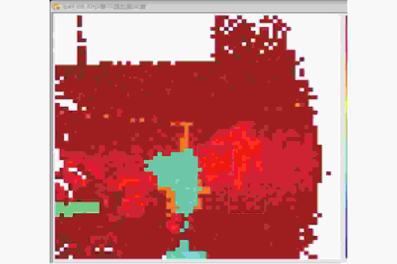
图 9 烟雾场景下无人机距离像
Figure 9. Range profile of UAV in smoke scenes
这是由于探测器在信号采集过程中接收到光子后便不会对后续的光子产生响应,即当经烟雾散射回来的光子引起探测器响应后,经目标反射的光子便不会再引起探测器响应,从而无法得到目标的距离像。由于经烟雾散射回来的光子与透过烟雾后再经目标反射回来的光子之间存在时间差,所以通过选通延时使得探测器在相应时间内关闭不会产生光子响应,达到滤除烟雾干扰的目的。
在相同条件下进行实验,发现当选通延时为43 ns时可获得如图10所示的距离像。从图中可看到较清晰无人机图像。因此,实验证明了通过主动激光成像可以滤除烟雾的影响,从而保证在烟雾遮挡条件下,避免了基于可见光图像的目标跟踪出现无法识别的情况。
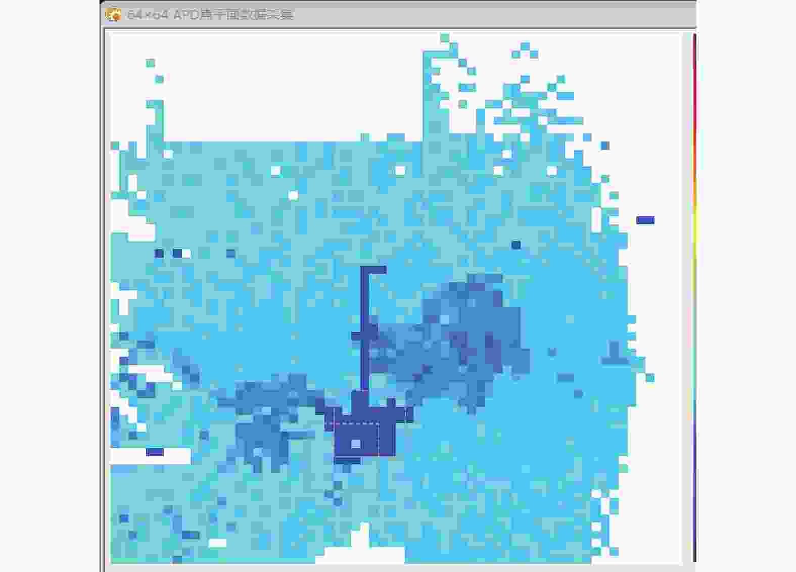
图 10 滤烟无人机距离像
Figure 10. Smoke filtering UAV range profile
-
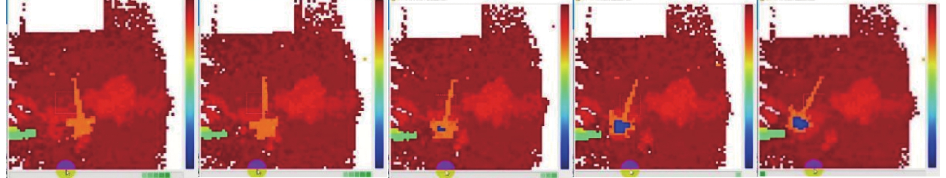
在室内通过开关控制灯泡的发光与熄灭模拟运动中的无人机突然燃烧起火。采集到的目标由正常运动到火光干扰下的运动这一过程的部分成像结果序列,如图11所示。可以看出,由于火光对目标的干扰影响,距离像中的目标被火光遮挡,即图11中蓝色部分,因而无法再看清楚无人机的轮廓。
基于图11的图像序列进行跟踪,得到图12所示的跟踪结果。由图12(a)可知在火光的影响下,当目标运动过程中燃烧起火时,距离像中的目标被火光噪声遮挡,造成跟踪框偏离目标。绘制目标的纵坐标随帧数变化的曲线图,如图12(b)所示。可以看出,当无人机运动中途受到强光照射影响时,即图示第29帧,目标出现失跟现象,对应图12(b)中第29帧时目标的纵坐标值突然出现急剧下降。
图 11 火光突变背景下部分成像序列
Figure 11. Partial imaging sequence under the background of firelight mutation
由于目标的失跟与距离像突变的蓝色部分(即火光距离像)的影响有关,因此在基于距离像跟踪时,可以看到滤除了火光噪声对目标的影响,可实现目标的稳定跟踪,如图13所示。
图 12 无人机距离像跟踪轨迹。 (a) 运动轨迹图像;(b) Y坐标轨迹曲线
Figure 12. Range profile tracking trajectory of UAV. (a) Motion trajectory image; (b) Y-coordinate trajectory curve

图 13 滤除火光后的目标距离像跟踪轨迹。 (a) 跟踪轨迹图像;(b) Y坐标轨迹曲线
Figure 13. Target range profile tracking trajectory after filtering out firelight. (a) Tracking trajectory image; (b) Y-coordinate trajectory curve
对比图13(b)和图12(b)可知,在第120帧时纵坐标未出现突变。由跟踪的最后一帧,计算得到图12(a)与图13(a)跟踪框的中心点,再与目标质心点进行较,得到了图12(a)中的跟踪框中心X、Y坐标偏离目标质心点分别为82.8 pixel和214 pixel,而图13(a)中跟踪框中心X、Y坐标偏离目标质心仅为1.5 pixel和1 pixel,即分别偏离约0.58 mrad和0.39 mrad。由此证明了采用距离像跟踪方法可实现目标在火光干扰条件下的较稳定跟踪。
-
针对火光烟雾条件下难探测无人机问题,基于距离像受火光和烟雾影响较小的特点,文中提出了一种基于主动激光雷达体制的高精度无人机瞄准方案。首先理论分析了火光烟雾条件下无人机的激光特性,然后设计了基于APD的单光子探测器的探测系统,最后搭建了基于InGaAs SPAD的光子成像系统,对成像系统进行测试并进行了室内实验。在无火光影响条件下,基于距离像跟踪的目标质心位置相较于可见光图像跟踪的目标质心位置平均偏移角弧度小于0.55 mrad,实验结果表明距离像序列跟踪法与可见光图像序列跟踪法的轨迹基本一致。在模拟烟雾条件下,通过选通延时滤除了烟雾影响,获得了轮廓清晰的目标距离像。实验结果表明跟踪框中心X、Y坐标偏离目标质心为0.58 mrad和0.39 mrad。文中研究结果为未来开展外场无人机探测和跟踪试验奠定了理论和实验基础。
Experimental research on laser detection and tracking of unmanned aerial vehicles under flame and smoke
-
摘要: 高能激光在打击低小慢目标时,目标容易燃烧产生火光烟雾,传统的可见光和红外探测方式对目标的跟踪和瞄准在火光烟雾干扰的情况下易受影响进而导致目标失跟。提出了一种基于主动激光雷达体制的高精度探测和瞄准方法。首先,对火光烟雾条件下无人机表面的激光反射特性进行理论分析和仿真模拟,以此设计了基于APD的单光子激光雷达探测系统,获得了仿真探测概率随激光脉冲能量变化的理论曲线;其次,构建了基于InGaAs-SPAD的光子成像探测系统,进行了无人机室内实验。实验结果表明:在无火光烟雾条件下,基于距离像跟踪的目标质心位置相较于基于可见光图像跟踪的目标质心位置平均角偏差小于0.55 mrad,基于距离像序列的跟踪轨迹与基于可见光图像序列的跟踪轨迹基本一致,证明了Mean-Shift跟踪算法用于距离像的跟踪的可行性。在距离30 m处的模拟烟雾干扰条件下,采用选通延时滤除烟雾干扰能够获得轮廓清晰的目标距离像。在模拟火光干扰条件下,跟踪框中心X、Y坐标偏离目标质心约为0.58 mrad和0.39 mrad。Abstract:
Objective In recent years, with the gradual opening of low altitude airspace and the continuous development of unmanned aerial vehicles (UAVs) technology, rapidly developing drones have been widely used in military, agriculture, transportation, public safety and other fields. However, due to the characteristics of simple operation, low cost, difficulty in supervision, and strong breakthrough ability, UAVs have caused many safety accidents and violent threats to social security and stability. Therefore, there is a strong demand for countermeasures against UAVs. With the development of laser weapons, the technology is becoming increasingly mature and has huge advantages in anti-UAVs. Under the action of high-energy laser, the target is prone to burning and catching fire, resulting in the target being blocked by flame smoke. Currently, visible light and infrared detection methods are easily affected by severe interference from flame and smoke, resulting in poor or unclear imaging of targets. Therefore, aiming at the problem that visible light and infrared detection methods cannot achieve stable tracking and aiming under flame and smoke, the paper studies a high-precision aiming scheme based on active lidar system. Methods The paper proposes a high-precision aiming scheme based on the active lidar system. Firstly, the laser characteristics under the flame and smoke were analyzed. Secondly, a lidar detection system based on APD single photon detector was designed. Then, the theoretical curve of the detection probability was simulated and analyzed as a function of the laser pulse energy. Finally, a photon imaging system based on InGaAs-SPAD was built, and the imaging system was tested and experimentally conducted indoors. Results and Discussions In the absence of the influence of fire and smoke, the X and Y coordinate trajectory curves of the target centroid based on visible light image tracking and range image tracking are basically consistent. By calculating the angular radian size of the target centroid position based on distance image tracking relative to the visible light tracking target centroid position, the X-coordinate angular radian curve and Y-coordinate angular radian curve were obtained (Fig.8). It is known that the average angular radian of the X-coordinate is about 0.55 mrad, and the average angular radian of the Y-coordinate is 0.53 mrad. By using a lidar system to collect range profiles under smoke, when the gating delay is 0 ns, the target is obstructed by smoke on the collected range profiles, making it impossible to obtain the image of the UAV (Fig.9). This is because when photons scattered by smoke cause detector response, photons reflected by the target will not cause detection starting point response, thus unable to obtain the range profiles of the target. Subsequently, through debugging under the same conditions, we obtained the range profiles for filtering out smoke obstruction when setting the gating delay to 43 ns (Fig.10). So active laser imaging can filter out the influence of smoke. In the experiment, the UAV was exposed to strong light during its movement, and under the sudden change conditions, the target lost track (Fig.12). Due to the correlation between the loss of target tracking and the impact of the blue part of the range profile mutation, when tracking based on the range profile, the influence of firelight noise on the target is filtered out, and the target is tracked (Fig.13). The deviation of the X and Y coordinates of the tracking rectangle center from the target centroid is 0.58 mrad and 0.39 mrad, and the target can be stably tracked within the range of the tracking rectangle under sudden changes in firelight. Conclusions The analysis of the optical characteristics of the firelight background and the laser attenuation characteristics of smoke shows that the radiance at 1 064 nm wavelength within the 10 nm narrowband filter passband is approximately 0.014 W/cm2; The transmittance range of laser in smoke is 60%-85%; In the case of backward scattering, fr is approximately 0.2-8 in the rough range of 0.2-0.8 μm. A lidar detection system is designed based on APD single photon detector, simulation analysis of the theoretical curve of detection probability changing with laser pulse energy. Under the conditions of this experiment, the optimal range for obtaining laser pulse energy is 0.75-4 mJ. Based on the above analysis, experimental verification of UAV lidar detection was conducted under smoke and fire backgrounds. Under the background without the influence of fire and smoke, the relative offset of the target centroid position based on range profile tracking to the target centroid position based on visible light image tracking is less than 0.55 mrad. Under simulated smoke conditions, clear contour target distance profiles were obtained by filtering out smoke effects through gating delay; Under simulated firelight mutation conditions, the X and Y coordinates of the tracking box center deviate from the target centroid by 0.58 mrad and 0.39 mrad. The experimental results show that this scheme can achieve imaging of unmanned aerial vehicles in the background of flame and smoke, and the Mean-Shift algorithm is used for range profile tracking, which compensates for the shortcomings of lighting mutation and easy loss of tracking when the background is similar to the target based on visible light image sequence tracking. -
Key words:
- flame and smoke /
- UAV /
- laser detection /
- range image /
- stable tracking
-
图 3 双向反射分布函数随入射角的变化规律。(a) ${\theta _r} = {30^ \circ }$时${f_r}$随${\theta _i}$变化曲线;(b) ${\theta _r} = {60^ \circ }$时${f_r}$随${\theta _i}$变化曲线
Figure 3. Variations of bidirectional reflection distribution function with incident angle. (a) curves of ${f_r}$ changing with ${\theta _i}$ at ${\theta _r} = {30^ \circ }$; (b) curves of ${f_r}$ changing with ${\theta _i}$ at ${\theta _r} = {60^ \circ }$
图 6 距离像跟踪获得的无人机轨迹结果。 (a) 运动轨迹图像;(b) 目标中心轨迹曲线
Figure 6. UAV trajectory by range profile tracking. (a) Motion trajectory image; (b) Target center trajectory curve
图 7 可见光跟踪无人机轨迹。 (a) 运动轨迹图像;(b) 目标中心轨迹曲线
Figure 7. UAV trajectory by visible light tracking. (a) Motion trajectory image; (b) Target center trajectory curve
图 8 距离像跟踪和可见光跟踪效果对比。 (a) X坐标轨迹; (b) X坐标角弧度曲线;(c) Y坐标轨迹; (d) Y坐标角弧度曲线
Figure 8. Comparison of range profile tracking and visible light tracking. (a) X-coordinate trajectory; (b) X-coordinate angle radian curve; (c) Y-coordinate trajectory; (d) Y-coordinate angle radian curve
图 11 火光突变背景下部分成像序列
Figure 11. Partial imaging sequence under the background of firelight mutation
图 12 无人机距离像跟踪轨迹。 (a) 运动轨迹图像;(b) Y坐标轨迹曲线
Figure 12. Range profile tracking trajectory of UAV. (a) Motion trajectory image; (b) Y-coordinate trajectory curve
图 13 滤除火光后的目标距离像跟踪轨迹。 (a) 跟踪轨迹图像;(b) Y坐标轨迹曲线
Figure 13. Target range profile tracking trajectory after filtering out firelight. (a) Tracking trajectory image; (b) Y-coordinate trajectory curve
表 1 仿真参数
Table 1. Simulation parameters
Parameter Value Laser wavelength ($\lambda $)/nm 1064 Laser divergence angle (${\theta _{{t} } }$)/mrad 10 Launch system efficiency (${\eta _{{t} } }$) 0.9 Receiving system efficiency ($ {\eta _r} $) 0.9 Effective receiving area of the detector ($ {A_r} $)/cm2 30 Atmospheric one-way transmittance (${\eta _{ {{atm} } } }$) 0.993 Filter bandwidth ($\Delta \lambda $)/nm 10 Dark counting rate (${N_d}$)/kHz 15-30 Target average reflectivity ($ \rho $) 0.3 The distance of the target (R)/m 30 Quantum efficiency of detector ($ {\eta _q} $) 20% $ \Delta t $/ns 1 d 30  下载: 导出CSV
表 2 APD探测器参数
Table 2. The APD detector parameters
APD detector parameters Minimum values Typical values Maximum values Pixel spacing/μm − 50 − Working wavelength/nm 950 − 1650 Time resolution/ns 1 − − Frame rate/kHz − − 25 Working voltage/V DC10 DC12 DC13 Operating temperature/℃ − −20 − Dark counting rate − 15% 30% Quantum efficiency of detector − 20% −
下载: 导出CSV
表 3 光学镜头参数
Table 3. Optical lens parameters
Optical lens parameters Typical values Receiving efficiency 90% Receiving area/cm2 30 Effective pixel rate 98%
下载: 导出CSV
-
[1] 刘军, 王鹤, 王秋玲, 刘小阳. 无人机遥感技术在露天矿边坡测绘中的应用 [J]. 红外与激光工程, 2016, 45(S1): 111-114. Liu Jun, Wang He, Wang Qiuling, et al. Application of UAV remote sensing technology in open-pit slop mapping [J]. Infrared and Laser Engineering, 2016, 45(S1): 111-114. (in Chinese) [2] Abderahman R, Alireza A, Karim R, et al. Drones in agriculture: A review and bibliometric analysis [J]. Computers and Electronics in Agriculture, 2022, 198: 107017. doi: 10.1016/j.compag.2022.107017 [3] Merlin S, Andreas S, Uwe J, et al. Maturity levels of public safety applications using unmanned aerial systems: A review [J]. Journal of Intelligent Robotic Systems, 2021, 103(1): 16. doi: 10.1007/s10846-021-01462-7 [4] Zongyao Y, Xueying Y, Simon D, et al. UAV remote sensing applications in marine monitoring: Knowledge visualization and review [J]. The Science of the Total Environment, 2022, 838(P1): 155939. [5] 王梓欣, 成炜, 辛颖, 等. 基于终端滑模控制的四旋翼无人机编队控制 [J]. 飞控与探测, 2023, 6(3): 44-51. Wang Zixin, Cheng Wei, Xin Ying, et al. Formation control of quadrotor UAV based on terminal sliding mode control [J]. Flight Control & Detection, 2023, 6(3): 44-51. (in Chinese) [6] Yaacoub J P, Noura H, Salman O, et al. Security analysis of drones systems: Attacks, limitations, and recommendations [J]. Internet of Things, 2020, 11: 100218. doi: 10.1016/j.iot.2020.100218 [7] 蒋罗婷. 当代反无人机系统技术综述 [J]. 电子质量, 2023, 2: 96-100. doi: 10.3969/j.issn.1003-0107.2023.02.021 Jiang Luoting. Review of modern counter drone systems technology [J]. Electronics Quality, 2023, 2: 96-100. (in Chinese) doi: 10.3969/j.issn.1003-0107.2023.02.021 [8] 杨辉跃, 简钰洪, 涂亚庆, 等. 反无人机视觉检测与跟踪技术进展分析 [J]. 国防科技, 2023, 44(3): 40-51. Yang Huiyue, Jian Yuhong, Tu Yaqing, et al. Review of anti-UAV visual detection and tracking technologies [J]. National Defense Science & Technology, 2023, 44(3): 40-51. (in Chinese) [9] 朱孟真, 陈霞, 刘旭, 等. 战术激光武器反无人机发展现状和关键技术分析 [J]. 红外与激光工程, 2021, 50(7): 20200230. doi: 10.3788/IRLA20200230 Zhu Mengzhen, Chen Xia, Liu Xu, et al. Situation and key technology of tactical laser anti-UAV [J]. Infrared and Laser Engineering, 2021, 50(7): 20200230. (in Chinese) doi: 10.3788/IRLA20200230 [10] 王茜, 冯寒亮. 德国莱茵金属公司高能激光的发展现状 [J]. 飞航导弹, 2017(7):3-8. [11] 穆作栋. 美国“利爪”反无人机激光武器系统分析[EB/OL]. (2019-07-01) [2024-03-13]https://mp.weixin.qq.com/s/ZTfLfXmNY-gTluz-ThdA1A. [12] 杨俊彦, 公发全, 刘锐, 等. 中红外激光在光电对抗领域的应用及进展 [J]. 飞控与探测, 2020, 3(6): 34-42. Yang Junyan, Gong Faquan, Liu Rui, et al. Application and progress of mid-infrared laser in optoelectronic countermeasure field [J]. Flight Control & Detection, 2020, 3(6): 34-42. (in Chinese) [13] 伍尚慧. 美国高能激光武器最新发展现状及趋势 [J]. 军事文摘, 2020(5):40-44. [14] 伍尚慧. 美军大力发展新型托盘化高能激光武器 [J]. 军事文摘, 2023(17):41-44. [15] 葛鹏, 郭静菁, 尚震. 基于面阵单光子探测器的激光三维成像 [J]. 电子技术与软件工程, 2019, 16: 129-130. Ge Peng, Guo Jingjing, Shang Zhen. Laser 3D imaging based on area array single photon detector [J]. Electronic Technology and Software Engineering, 2019, 16: 129-130. (in Chinese) [16] Lindell D B, Wetzstein G, O' Toole M. Wave-based non-line-of sight imaging using fast f-k migration [J]. ACM Transactions on Graphics, 2019, 38(4): 1-13. [17] 陈勇强, 贺岩, 罗远, 等. 基于盖革APD阵列脉冲式三维成像激光雷达系统 [J]. 中国激光, 2023, 50(2): 97-106. Chen Yongqiang, He Yan, Luo Yuan, et al. Pulsed three-dimensional imaging lidar system based on geiger-mode APD array [J]. Chinese Journal of Lasers, 2023, 50(2): 0210001. (in Chinese) -

 点击查看大图

计量
- 文章访问数: 28
- HTML全文浏览量: 13
- PDF下载量: 13
- 被引次数: 0

