


-
中红外波段2 μm固体激光器在输出波长方面具有独特特点:处于大气窗口、水的吸收带和人眼安全区。基于这些特殊属性,它可以被广泛应用于激光成像雷达、多普勒相干测风雷达以及差分吸收雷达等用于测量地球大气浓度和温度变化的激光光源[1-5]。此外,2 μm波段的激光还可以作为光学参量振荡器的泵浦源,实现更长波段的红外激光输出。
随着人们对2 μm固体激光器研究的不断深入,热效应问题成为限制激光器输出功率和光束质量提升的主要难题,因此备受关注[6]。在固体激光器运行时,热量的产生源于量子亏损、下激光能级与基态之间的能量转换,以及激光猝灭等因素,这导致激光晶体内部温度分布不均,从而引发热透镜效应[7-11]。然而,通过利用键合技术将YAG晶体与Tm:YAG晶体键合在一起,构成复合晶体作为激光器的工作材料,可以有效减少热效应的影响,使用复合晶体的激光器具有高可靠性、高峰值功率和优良的光斑质量等优点[12-14]。
为了有效减少激光晶体内的热效应,本研究通过引入两种复合晶体模型(即单端键合和双端键合)来降低激光晶体的热效应。通过分析连续LD端面泵浦方形复合Tm:YAG晶体的工作特点,构建激光晶体体热源热模型,考虑晶体端面与空气发生热对流以及周边恒温的边界条件,利用有限元分析法,对于激光二极管端泵方形复合Tm:YAG晶体的热效应进行研究,分析了键合晶体厚度分别对单端键合、双端键合的激光晶体内部温度场分布及形变量分布的影响;分析了当YAG晶体厚度一致时,增益晶体厚度对两种不同键合方式的复合晶体内部最大温升的影响。结果表明,在理想的冷却条件下在Tm:YAG晶体端面键合YAG晶体可以有效减少晶体的热效应,且在一定条件下双端键合的方式降低晶体热效应的效果更好。
-
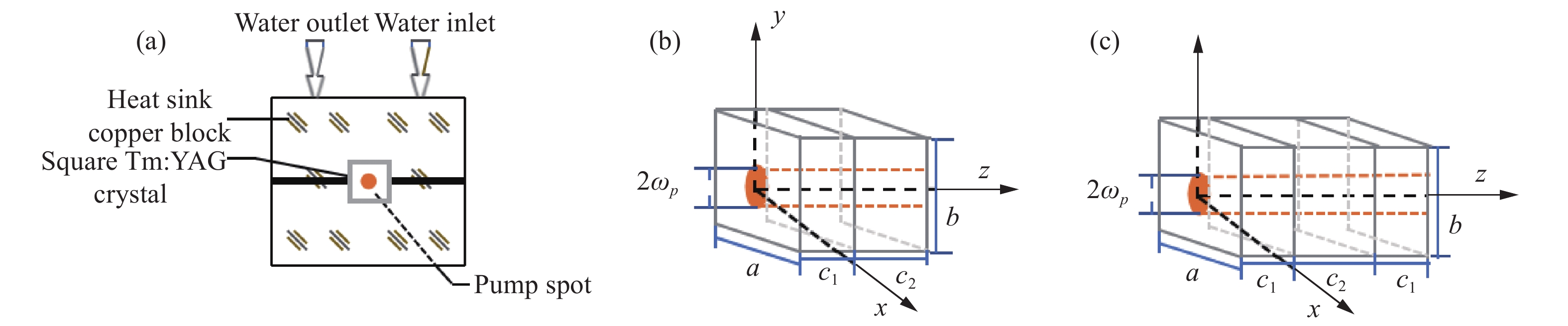
采用连续LD端面泵浦的方形Tm:YAG复合晶体,实验装置如图1 所示。M1为全反平面镜,M2为输出凹面镜,将Tm:YAG晶体置于平面镜M1和凹面镜M2之间。

图 1 脉冲LD端泵浦Tm:YAG激光器的腔体结构图
Figure 1. Cavity structure diagram of pulsed LD end pumped Tm:YAG laser
为使激光晶体吸收泵浦光产生的热量尽快地散失,依据激光晶体几何尺寸以及激光器谐振腔光路,加工了热沉装置,结构简图如图2 所示。为了确保激光晶体与热沉之间的热胀一致性,将激光晶体夹在两个热沉紫铜块之间,在接触面上涂抹了银粉,并在银粉上垫上150 μm厚的铟膜,来确保晶体与热沉之间良好的热接触,使用循环水冷方式控制热沉铜块的温度。其中复合晶体尺寸为 a mm×b mm×c mm,c1为YAG晶体(未掺杂晶体)厚度,c2为Tm:YAG(增益晶体)厚度。

图 2 方形Tm:YAG晶体模型及其热沉实验装置结构简图。(a)热沉实验装置;(b)单端键合晶体模型;(c)双端键合晶体
Figure 2. Structure schematic diagram of square Tm:YAG crystal model and heat sink experimental device . (a) Heat sink experimental device; (b) Single-ended bonded crystal model; (c) Double-ended bonded crystals
-
半导体激光器发出的泵浦光经过耦合透镜等一些光学系统后,对晶体端面进行泵浦。可以粗略用高斯函数来近似泵浦光光强的空间分布,假设泵浦光与z轴是平行的,光场的中心与光学系统的中心相重合,入射到泵浦面(z=0)的泵浦光分布表达式为:
$$ I\left( {x,y,0,} \right) = {I_{\text{0}}}\exp \left[ { - 2\frac{{\left( {{x^2} + {y^2}} \right)}}{{\omega _{{{\rm{p}}}}^{\text{2}}}}} \right] $$ (1) 式中:${\omega }_{{\rm{p}}}$为泵浦光光斑半径;$ {I}_{0} $为激光二极管泵浦光强。
$$ {I_0} = \frac{{2{P_{{\text{in}}}}}}{{{\text{π }}\omega _{\text{p}}^{\text{2}}}} $$ (2) 式中:${P}_{{\rm{in}}}$为泵浦光功率;α为方形Tm:YAG复合晶体对泵浦光的吸收系数。在方形激光晶体中,当泵浦光传输时,光能逐渐被吸收,导致在方形晶体内的不同位置处的热沉积不同[10],泵浦光沿z轴传播的光强表示为:
$$ \begin{gathered} I\left( {x,y,z} \right) = {I_0} \cdot {\text{exp}}\left[ {{{ - 2\left( {{x^2} + {y^2}} \right)} \mathord{\left/ {\vphantom {{ - 2\left( {{x^2} + {y^2}} \right)} {{\omega ^2}\left( z \right)}}} \right. } {{\omega ^2}\left( z \right)}}} \right] \cdot {\text{exp}}\left[ { - {\text{α }}\left( {z - {c_1}} \right)} \right] \\ \end{gathered} $$ (3) 式中:$ \mathrm{\omega } $(z)为泵浦光在激光晶体内z处的光斑半径。则$ \mathrm{\omega } $(z)表示为[15]:
$$ \omega \left( z \right) = {\omega _p}\sqrt {1 + {{\left( {\frac{{\lambda z}}{{\pi \omega _{\rm{p}}^2}}} \right)}^2}} $$ (4) 由公式(4)可知,泵浦光在激光晶体z处的光斑半径近似等于${\omega }_{{\rm{p}}}$的大小。则Tm:YAG晶体棒吸收泵浦光产生的热功率密度表示为:
$$ Q(x, y, z)=\frac{2 \eta \alpha P_{\mathrm{in}} \exp \left[-2\left(x^2+y^2\right) / \omega_{\rm{p}}^2\right] \exp \left[-\alpha\left(z-c_1\right)\right]}{\pi \omega_{\rm{p}}^2} $$ (5) 式中:η为晶体棒的热转换系数,$ \eta=1-\lambda_{\text {pump }} / \lambda_{\text {laser }} $,$ {{{\lambda }}_{{\text{pump}}}} $($ {{{\lambda }}_{{\text{pump}}}}{\text{ = 780 nm}} $)为泵浦光波长,$ {{{\lambda }}_{{\text{laser}}}} $(${{{\lambda }}_{{\text{laser}}}}$=2 014 nm)为输出波长。方形Tm:YAG复合晶体被热沉铜块包裹,通过循环水冷周边散热保持热沉铜块温度恒定,属于第一类边界条件。晶体的两个端面直接接触空气,与空气有热交换过程,发生热对流,属于第三类边界条件。方形晶体的边界条件为:
$$ \left\{ \begin{gathered} T\left( {-a/2,y,z} \right) = {T_0};T\left( {a/2,y,z} \right) = {T_0} \\ T\left( {x,-b/2,z} \right) = {T_0};T\left( {x,b/2,z} \right) = {T_0} \\ \end{gathered} \right. $$ (6) $$\left\{\begin{array}{l} {K}_c(T-{T} \infty)-\left.{{{h}}} \dfrac{\partial T}{\partial z}\right|_{z=0}=0 \\ {~K}_c(T-{T} \infty)+\left.{h} \dfrac{\partial T}{\partial z}\right|_{z=c}=0 \end{array}\right.$$ (7) 式中:h为晶体表面与空气热交换系数,${{T}}\infty$为初始温度。
-
Parameter Value $ \mathrm{D}\mathrm{e}\mathrm{n}\mathrm{s}\mathrm{i}\mathrm{t}\mathrm{y}/\mathrm{g}\cdot{\mathrm{c}\mathrm{m}}^{-3} $ 4.56 $ \mathrm{T}\mathrm{h}\mathrm{e}\mathrm{r}\mathrm{m}\mathrm{a}\mathrm{l}\;\;\mathrm{c}\mathrm{o}\mathrm{n}\mathrm{d}\mathrm{u}\mathrm{c}\mathrm{t}\mathrm{i}\mathrm{v}\mathrm{i}\mathrm{t}\mathrm{y}/\mathrm{W}\cdot {\mathrm{m}}^{-1}\cdot {\mathrm{K}}^{-1} $ 14 $ \mathrm{S}\mathrm{p}\mathrm{e}\mathrm{c}\mathrm{i}\mathrm{f}\mathrm{i}\mathrm{c}\;\;\mathrm{h}\mathrm{e}\mathrm{a}\mathrm{t}/\mathrm{J}\cdot {\mathrm{g}}^{-1}\cdot {\mathrm{K}}^{-1} $ 0.59 $ \mathrm{C}\mathrm{o}\mathrm{e}\mathrm{f}\mathrm{f}\mathrm{i}\mathrm{c}\mathrm{i}\mathrm{e}\mathrm{n}\mathrm{t}\;\;\mathrm{o}\mathrm{f}\;\;\mathrm{t}\mathrm{h}\mathrm{e}\mathrm{r}\mathrm{m}\mathrm{a}\mathrm{l}\;\;\mathrm{e}\mathrm{x}\mathrm{p}\mathrm{a}\mathrm{n}\mathrm{s}\mathrm{i}\mathrm{o}\mathrm{n}/{\mathrm{K}}^{-1} $ 8×10⁶ Initial temperature/K 291 Water cooling temperature/K 288.15 利用有限元方法计算方形复合Tm:YAG晶体的温度场分布如图3所示,所用参数见表1。由图3可知:当泵浦功率P = 30 W、光斑半径${\omega }_{{\rm{p}}}$= 400 μm、YAG晶体厚度c1=1 mm 时,Tm:YAG 晶体厚度c2= 1.5 mm,由于键合面上温度较高,而作为热沉的YAG晶体可以有效地吸收激光晶体中的热量,由于复合晶体键合面有效的热传导,故整个键合晶体内部最大温度不在增益晶体靠近泵浦面端面;键合晶体在z=c1平面的温度分布是沿z轴的中心对称结构,温度最大值出现在端面中央位置,离中心越远,温度逐渐越低,在中心位置周围下降最厉害,类似圆环阶梯型分布;越靠近外围,越接近散热铜块,越有利于热量传递,所以温度也更加的低。这与理论情况是相符的。分析图中数据可得到:单端键合Tm:YAG复合晶体内最高温升可达81.2 ℃,增益晶体端面中央最大温度为61.6 ℃比晶体中心温度降低19.6 ℃;双端键合Tm:YAG复合晶体内最高温升可达77.9 ℃,增益晶体端面中央最大温度为58.2 ℃,比晶体中心温度降低19.7 ℃。验证了键合晶体对晶体端面热效应有显著改善作用;当YAG晶体厚度c1=1 mm 时,Tm:YAG 晶体厚度c2= 1.5 mm,双端键合比单端键合降低晶体内部最大温度的效果更好。

图 3 方形Tm:YAG复合晶体温度三维分布图。(a)单端键合晶体纵截面(y=0);(b)单端键合的增益晶体端面(z=c1);(c)双端键合晶体纵截面(y=0);(d)双端键合的增益晶体端面(z=c1)
Figure 3. Three-dimensional temperature distribution of square composite Tm:YAG crystal. (a) Longitudinal section of single-ended bonded crystal (y=0); (b) single-ended bonded gain crystal end face (z=c1); (c) Longitudinal section of double-ended bonded crystal (y=0); (d) Double-ended bonded gain crystal end face (z=c1)
-
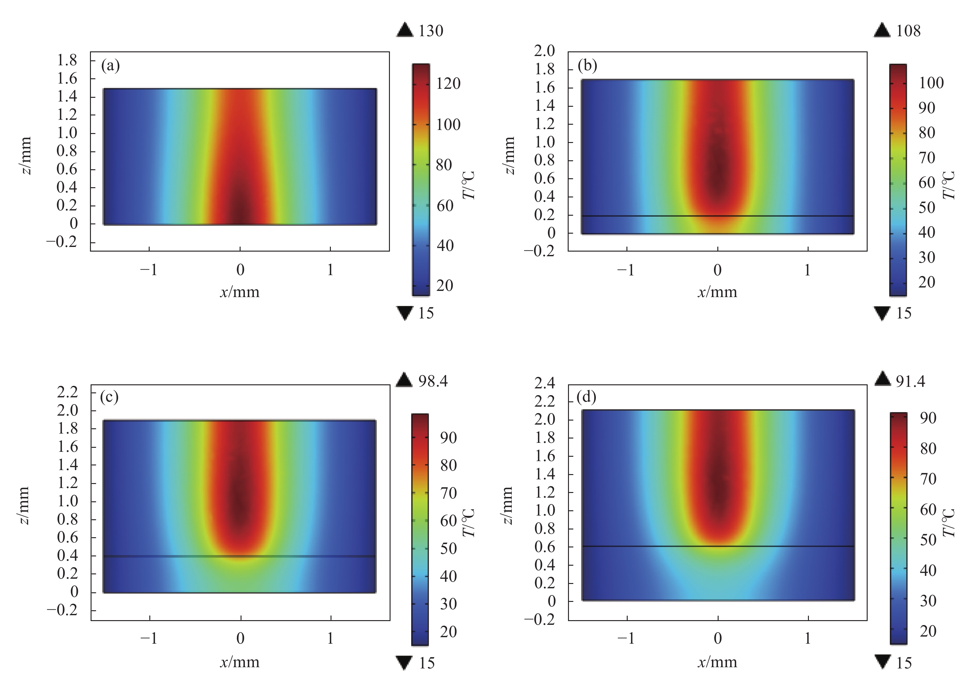
由图4及图5可知,其他参数条件不变时,采用复合晶体可以显著降低激光晶体的温度。当YAG 晶体厚度($ {c}_{1} $)为0、0.2、0.4、0.6 mm时,单端键合复合晶体内沿着z轴方向上的最高温升分别为130、108、98.4、91.4 ℃;双端合复合晶体内沿着z轴方向上的最高温升分别为130、107、95.1、88.3 ℃。由数据分析可知:当YAG晶体厚度在0~0.6 mm,增益晶体厚度为1.5 mm时,双端键合的方式比单端键合的方式降低激光晶体温度效果更好;但是随着两种键合方式的未掺杂晶体厚度(c1)逐渐增大,最高温度的下降趋势越来越缓慢。

图 4 单端键合晶体侧面剖面温度分布图(x=0)。(a) $ {c}_{1} $=0 mm;(b) $ {c}_{1} $=0.2 mm;(c) $ {c}_{1} $=0.4 mm;(d) $ {c}_{1} $=0.6 mm
Figure 4. Temperature profile of single-ended bonded crystal (x=0). (a) $ {c}_{1} $=0 mm; (b) $ {c}_{1} $=0.2 mm; (c) $ {c}_{1} $=0.4 mm; (d) $ {c}_{1} $=0.6 mm

图 5 双端键合晶体侧面剖面温度分布图(y=0)。(a) c1=0.2 mm;(b) c1=0.4 mm;(c) c1=0.6 mm
Figure 5. Temperature profile of double-ended bonded crystal (y=0). (a) c1=0.2 mm; (b) c1=0.4 mm; (c) c1=0.6 mm
-
由图6可知,其他参数条件不变时,YAG晶体厚度为1 mm时,Tm:YAG 晶体厚度$ {c}_{2} $由1 mm增加至2.8 mm,单端键合复合晶体内最大温度基本处于81 ℃左右;而双端合复合晶体内最高温升由72.3 ℃升为81 ℃左右,当Tm:YAG 晶体厚度$ {c}_{2} $为2.6 mm之后,双端键合晶体温度趋于平稳且与单端键合晶体温度基本吻合。由此说明,当YAG晶体厚度1 mm时,增益晶体厚度在1~2.6 mm之间时,双端键合方式降低晶体温度的效果比单端键合方式好,但增益晶体厚度在2.6 mm之后,两种键合方式的复合晶体的温度基本保持一致。这是由于泵浦光在Tm:YAG晶体中被吸收后逐渐减弱,当泵浦光传播到Tm:YAG晶体厚度大于2.6 mm时,泵浦光光强减弱到一定程度,键合在增益晶体尾部作为热沉的YAG晶体对于降低晶体内部最大温度没有发挥作用,故两种键合方式的复合晶体的温度基本保持一致。

图 6 复合晶体内最大温度随增益晶体厚度的变化
Figure 6. The maximum temperature in the composite crystal varies with the thickness of the gain crystal
-
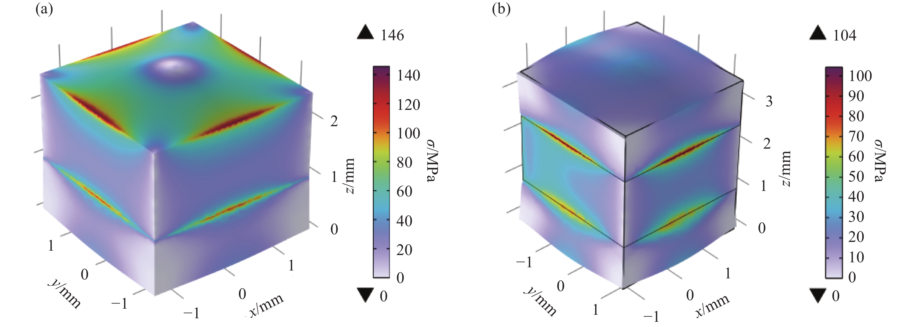
图7~8为方形Tm:YAG复合晶体热应力分布图。由图可知:当泵浦功率P = 30 W,光斑半径${\omega }_{{\rm{p}}}$= 400 μm,YAG晶体厚度c1=1 mm 时,Tm:YAG晶体 厚度c2= 1.5 mm,对于Tm:YAG复合晶体内部应力影响较大的在其增益晶体端面处,且最大应力均集中在边缘处,边缘处应力高于其他区域;单端和双端键合的复合晶体内部最大热应力分别为146、104 MPa。分析数据可以得出,双端键合降低晶体内部最大应力效果更好。
如图9所示为方形Tm:YAG复合晶体侧剖面热形变三维分布图。由图可知:泵浦功率P = 30 W,光斑半径${\omega }_{{\rm{p}}}$= 400 μm,YAG晶体厚度c1=1 mm,Tm:YAG 晶体厚度c2= 1.5 mm时,激光二极管端面泵浦单端键合的方形Tm:YAG复合晶体的最大热形变在晶体尾部,此平面内最大形变值为0.468 μm,沿z轴负方向环形递减,并在增益晶体入射端面时逐渐变大,这说明当c1=1 mm,单端键合晶体的形变量影响最大的是晶体尾部;激光二极管端泵双端键合的方形Tm:YAG复合晶体的最大热形变在复合晶体端面,此平面内最大形变量为0.172 μm,沿z轴环形递减后增大,这说明当c1=1 mm,双端键合晶体的形变量影响最大的是晶体泵浦面。
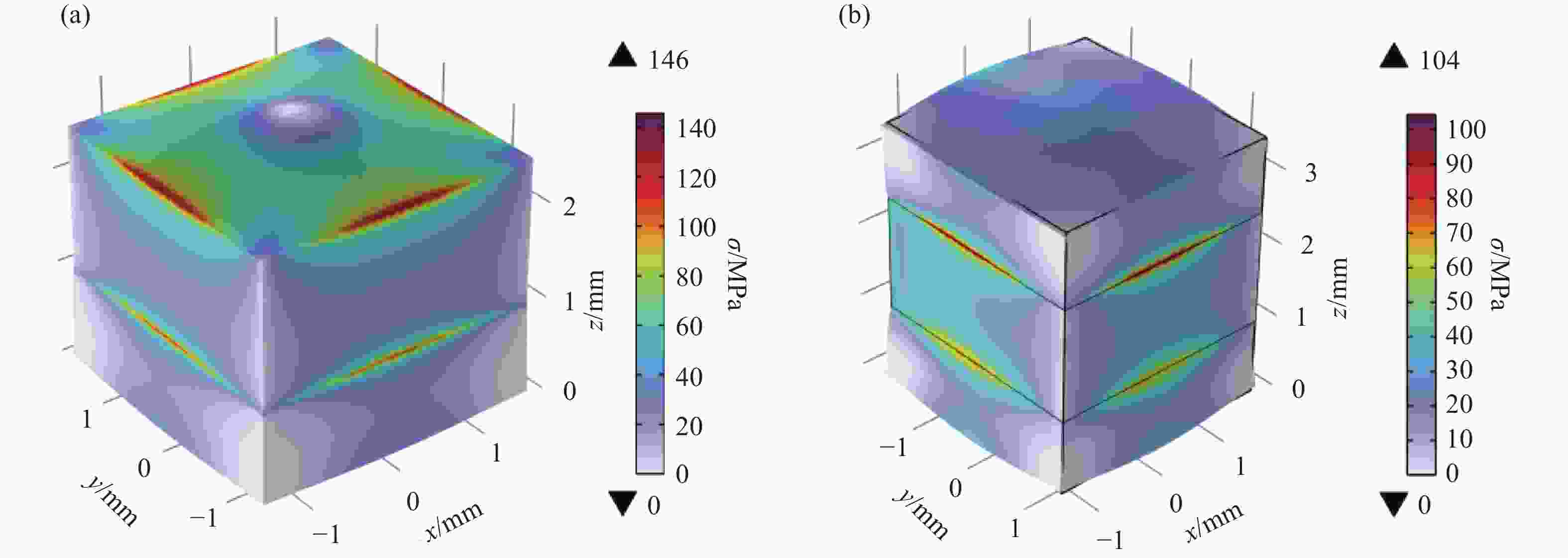
图 7 YAG/Tm:YAG晶体应力分布图。(a)单端键合;(b)双端键合
Figure 7. Stress distribution of YAG/Tm:YAG crystals. (a) Single-ended bonding; (b) Double-ended bonding

图 8 YAG/Tm:YAG晶体侧面剖面应力分布图(x=0)。(a)单端键合;(b)双端键合
Figure 8. YAG/Tm:YAG crystal side profile stress distribution(x=0). (a) Single-ended bonding; (b) Double-ended bonding
-
激光二极管端面泵浦单端键合的方形复合Tm:YAG晶体侧剖面形变量分布如图10所示。由图可知:当激光晶体未键合YAG晶体时,最大形变值为0.683 μm,当YAG晶体厚度由0.2 mm增加到0.6 mm,复合晶体的最大形变量由0.564 μm降为0.507 μm。此数据可说明,单端键合可有效降低晶体内部最大形变量,且随着YAG晶体厚度的增加,晶体内部最大热形变量减小;当激光晶体未键合以及键合YAG晶体厚度较小的情况下,激光晶体影响形变量最大的在泵浦面处,而复合晶体键和长度增大到一定长度时,对激光晶体形变量影响最大的变为晶体尾部。

图 9 复合晶体热形变三维分布图(y=0)。(a)单端键合;(b)双端键合
Figure 9. Three-dimensional distribution of thermal deformation of composite crystal (y=0). (a) Single-ended bonding; (b) Double-ended bonding
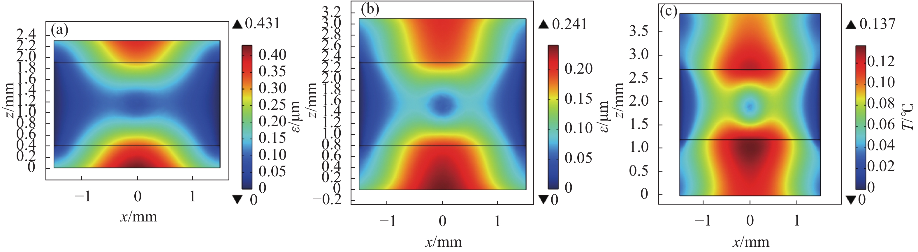
激光二极管端面泵浦双端键合的方形复合Tm:YAG晶体侧剖面形变量分布如图11所示。由图可知:当YAG晶体厚度由0.4 mm增加到1.2 mm,复合晶体的最大形变量由0.431 μm降为0.137 μm。此数据可说明,随着YAG晶体厚度的增加,晶体内部最大热形变量减小,双端键合可有效降低晶体内部最大形变量,当YAG晶体厚度逐渐增大时,对于激光晶体形变量影响较大的由泵浦面处变为由增益晶体入射端面附近。
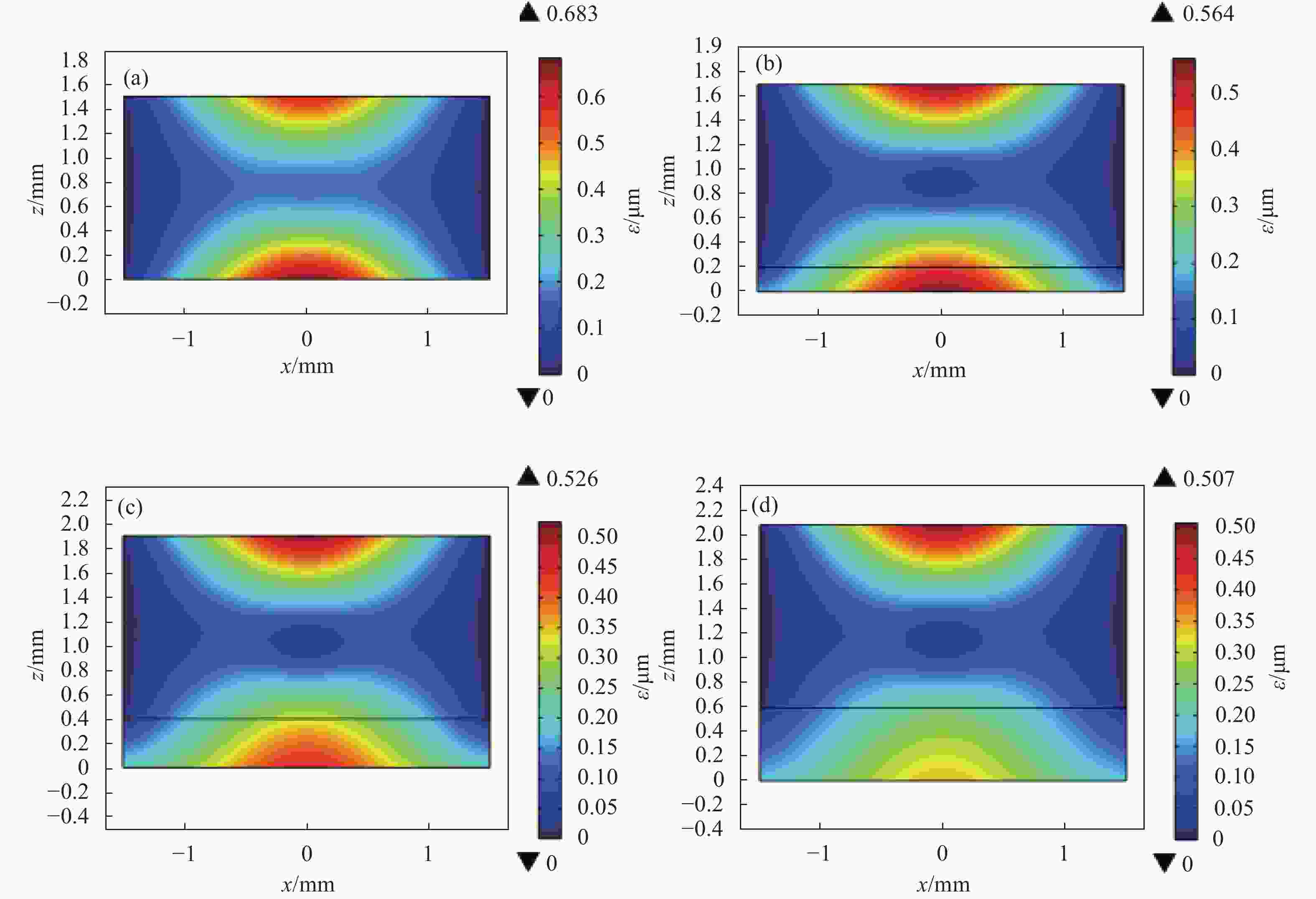
图 10 单端键合Tm:YAG复合晶体侧面剖面形变量分布图(y=0)。 (a) $ {c}_{1} $=0 mm;(b) $ {c}_{1} $=0.2 mm;(c) $ {c}_{1} $=0.4 mm;(d) c1=0.6 mm
Figure 10. Profile profile variable distribution of single-ended bonded Tm:YAG composite crystal (y=0). (a) $ {c}_{1} $=0 mm;(b) $ {c}_{1} $=0.2 mm;(c) $ {c}_{1} $=0.4 mm;(d) c1=0.6 mm
对比分析数据可知,当Tm:YAG晶体厚度为1.5 mm时,激光二极管端泵双端键合方形Tm:YAG复合晶体相较于单端键合方形Tm:YAG复合晶体更为有效降低晶体内部最大热形变量。

图 11 双端键合Tm:YAG复合晶体侧面剖面形变量分布图(x=0)。(a) c1=0.4 mm;(b) c1=0.8 mm;(c) c1=1.2 mm
Figure 11. Double-ended bond Tm:YAG composite crystal profile profile variable distribution (x=0). (a) c1=0.4 mm; (b) c1=0.8 mm; (c) c1=1.2 mm
-
文中根据热传导理论,使用有限元分析法,研究了激光二极管端面泵浦单端键合和双端键合的 Tm:YAG 复合晶体热效应,可得出复合晶体可有效减少晶体中最大温升和晶体内部热变形的结论。且当满足一定条件时,双端键合会表现出更好的效果。在设计激光系统时,需要注意防止晶体由于过高的温度而受损,并适当增加未掺杂晶体厚度来降低激光器热效应,为输出高功率激光提供更优的条件,也为进一步设计热性能更好的Tm:YAG 激光器提供理论依据。
Thermal effect of laser diode end pump square Tm:YAG composite crystal
-
摘要: 为了有效解决激光二极管端面泵浦激光晶体引起的热效应问题,引入复合晶体的概念,通过两种复合晶体模型(即单端键合和双端键合)来降低激光晶体的热效应。根据激光二极管端面泵浦激光晶体工作特点,建立端面泵浦方形 Tm:YAG复合晶体热模型,利用热传导理论,用有限元分析法对复合晶体的温度场、热应力场和形变量进行了数值计算,分析了单端/双端键合方式、未掺杂晶体长度、增益晶体长度对方形复合晶体内部温度场及形变量的影响。结果表明,平衡状态下,激光二极管泵浦功率为30 W、泵浦光斑半径为400 μm时,YAG晶体厚度c1为1 mm,增益晶体厚度c2为1.5 mm,方形单端键合和双端键合的Tm:YAG复合晶体内部最大温升分别为81.2、77.9 ℃;内部最大应力分别为146、104 MPa;热形变量为0.468、0.172 μm。可见,复合晶体能有效缓解晶体的温升和热形变,且双端键合的方式降低晶体热效应的效果更好。当增益晶体厚度为2.6 mm以上时,两种键合方式对复合晶体内部最大温升的影响基本保持一致。该研究为方形Tm:YAG复合晶体的增益晶体厚度、未掺杂晶体厚度的选择提供了参考依据,也为实现 Tm:YAG 激光器高功率输出目标提供了理论指导。Abstract:
Objective The mid-infrared 2 μm solid-state laser has unique characteristics in terms of output wavelength: it is in the atmospheric window, the absorption band of water and the human eye safety zone. Based on these special properties, it can be widely used in laser imaging radar, doppler coherent wind radar, differential absorption radar and other laser sources used to measure the concentration and temperature changes of the earth's atmosphere. In addition, the 2 μm band laser can also be used as a pump source for optical parametric oscillators to achieve longer wavelength infrared laser output. With the deepening of research on 2 μm solid-state lasers, thermal effect has become a major problem limiting laser output power and beam quality improvement, so it has attracted much attention. During the operation of solid-state lasers, the heat generation is due to quantum deficit, energy conversion between the lower laser level and the ground state, and laser quenching, which leads to uneven temperature distribution inside the laser crystal, resulting in thermal lensing effect. However, by using bonding technology to bond YAG crystals with Tm:YAG crystals to form composite crystals as the working material of lasers, the influence of thermal effect can be effectively reduced. Lasers using composite crystals have advantages such as high reliability, peak power and excellent spot quality Methods In this paper, the thermal effect of laser crystals is reduced by introducing two composite crystal models, namely single-ended bond and double-ended bond. By analyzing the working characteristics of continuous LD end-pumped square composite Tm:YAG crystal, a heat source heat model of laser crystal (Square Tm:YAG crystal model and its heat sink experimental device structure schematic diagram as shown in Fig.2) is constructed. Considering the boundary conditions of thermal convection between the crystal rod end face and air and the surrounding constant temperature, the finite element analysis method is used. The thermal effect of laser diode end pump square composite Tm:YAG crystal is studied. Results and Discussions The thermal model of laser crystal is established which is more suitable for the actual working conditions. The temperature field, thermal stress field and end shape variables of the composite crystal are numerically calculated by finite element analysis. The effects of single/double end bonding, undoped crystal length and gain crystal length on the internal temperature field and end shape variables of the square composite crystal are discussed. The bonded crystals can significantly improve the thermal effect of crystal end faces. Conclusions The thermal model of laser crystal is established which is more suitable for the actual working conditions. When the pump power of the laser diode is 30 W, the radius of the pump spot is 400 μm, the thickness of YAG crystal is 1 mm, and the thickness of gain crystal is 1.5 mm, the maximum internal temperature rise of the square single-ended and double-ended Tm:YAG composite crystal are 81.2 ℃ and 77.9 ℃ respectively. The maximum internal stresses are 146 MPa and 104 MPa respectively. The thermal shape variables are 0.468 μm and 0.172 μm. It can be seen that the composite crystal can effectively alleviate the temperature rise of the crystal and the thermal deformation of the crystal end face, and the double-end bonding has a better effect on reducing the thermal effect of the crystal. When the thickness of the gain crystal is more than 2.6 mm, the influence of the two bonding methods on the maximum temperature rise inside the composite crystal is basically the same. -
Key words:
- laser diode /
- temperature field /
- thermal deformation /
- composite crystal /
- single-ended bonding /
- double-ended bonding
-
图 1 脉冲LD端泵浦Tm:YAG激光器的腔体结构图
Figure 1. Cavity structure diagram of pulsed LD end pumped Tm:YAG laser
图 2 方形Tm:YAG晶体模型及其热沉实验装置结构简图。(a)热沉实验装置;(b)单端键合晶体模型;(c)双端键合晶体
Figure 2. Structure schematic diagram of square Tm:YAG crystal model and heat sink experimental device . (a) Heat sink experimental device; (b) Single-ended bonded crystal model; (c) Double-ended bonded crystals
图 3 方形Tm:YAG复合晶体温度三维分布图。(a)单端键合晶体纵截面(y=0);(b)单端键合的增益晶体端面(z=c1);(c)双端键合晶体纵截面(y=0);(d)双端键合的增益晶体端面(z=c1)
Figure 3. Three-dimensional temperature distribution of square composite Tm:YAG crystal. (a) Longitudinal section of single-ended bonded crystal (y=0); (b) single-ended bonded gain crystal end face (z=c1); (c) Longitudinal section of double-ended bonded crystal (y=0); (d) Double-ended bonded gain crystal end face (z=c1)
图 4 单端键合晶体侧面剖面温度分布图(x=0)。(a) $ {c}_{1} $=0 mm;(b) $ {c}_{1} $=0.2 mm;(c) $ {c}_{1} $=0.4 mm;(d) $ {c}_{1} $=0.6 mm
Figure 4. Temperature profile of single-ended bonded crystal (x=0). (a) $ {c}_{1} $=0 mm; (b) $ {c}_{1} $=0.2 mm; (c) $ {c}_{1} $=0.4 mm; (d) $ {c}_{1} $=0.6 mm
图 5 双端键合晶体侧面剖面温度分布图(y=0)。(a) c1=0.2 mm;(b) c1=0.4 mm;(c) c1=0.6 mm
Figure 5. Temperature profile of double-ended bonded crystal (y=0). (a) c1=0.2 mm; (b) c1=0.4 mm; (c) c1=0.6 mm
图 6 复合晶体内最大温度随增益晶体厚度的变化
Figure 6. The maximum temperature in the composite crystal varies with the thickness of the gain crystal
图 7 YAG/Tm:YAG晶体应力分布图。(a)单端键合;(b)双端键合
Figure 7. Stress distribution of YAG/Tm:YAG crystals. (a) Single-ended bonding; (b) Double-ended bonding
图 8 YAG/Tm:YAG晶体侧面剖面应力分布图(x=0)。(a)单端键合;(b)双端键合
Figure 8. YAG/Tm:YAG crystal side profile stress distribution(x=0). (a) Single-ended bonding; (b) Double-ended bonding
图 9 复合晶体热形变三维分布图(y=0)。(a)单端键合;(b)双端键合
Figure 9. Three-dimensional distribution of thermal deformation of composite crystal (y=0). (a) Single-ended bonding; (b) Double-ended bonding
图 10 单端键合Tm:YAG复合晶体侧面剖面形变量分布图(y=0)。 (a) $ {c}_{1} $=0 mm;(b) $ {c}_{1} $=0.2 mm;(c) $ {c}_{1} $=0.4 mm;(d) c1=0.6 mm
Figure 10. Profile profile variable distribution of single-ended bonded Tm:YAG composite crystal (y=0). (a) $ {c}_{1} $=0 mm;(b) $ {c}_{1} $=0.2 mm;(c) $ {c}_{1} $=0.4 mm;(d) c1=0.6 mm
图 11 双端键合Tm:YAG复合晶体侧面剖面形变量分布图(x=0)。(a) c1=0.4 mm;(b) c1=0.8 mm;(c) c1=1.2 mm
Figure 11. Double-ended bond Tm:YAG composite crystal profile profile variable distribution (x=0). (a) c1=0.4 mm; (b) c1=0.8 mm; (c) c1=1.2 mm
Parameter Value $ \mathrm{D}\mathrm{e}\mathrm{n}\mathrm{s}\mathrm{i}\mathrm{t}\mathrm{y}/\mathrm{g}\cdot{\mathrm{c}\mathrm{m}}^{-3} $ 4.56 $ \mathrm{T}\mathrm{h}\mathrm{e}\mathrm{r}\mathrm{m}\mathrm{a}\mathrm{l}\;\;\mathrm{c}\mathrm{o}\mathrm{n}\mathrm{d}\mathrm{u}\mathrm{c}\mathrm{t}\mathrm{i}\mathrm{v}\mathrm{i}\mathrm{t}\mathrm{y}/\mathrm{W}\cdot {\mathrm{m}}^{-1}\cdot {\mathrm{K}}^{-1} $ 14 $ \mathrm{S}\mathrm{p}\mathrm{e}\mathrm{c}\mathrm{i}\mathrm{f}\mathrm{i}\mathrm{c}\;\;\mathrm{h}\mathrm{e}\mathrm{a}\mathrm{t}/\mathrm{J}\cdot {\mathrm{g}}^{-1}\cdot {\mathrm{K}}^{-1} $ 0.59 $ \mathrm{C}\mathrm{o}\mathrm{e}\mathrm{f}\mathrm{f}\mathrm{i}\mathrm{c}\mathrm{i}\mathrm{e}\mathrm{n}\mathrm{t}\;\;\mathrm{o}\mathrm{f}\;\;\mathrm{t}\mathrm{h}\mathrm{e}\mathrm{r}\mathrm{m}\mathrm{a}\mathrm{l}\;\;\mathrm{e}\mathrm{x}\mathrm{p}\mathrm{a}\mathrm{n}\mathrm{s}\mathrm{i}\mathrm{o}\mathrm{n}/{\mathrm{K}}^{-1} $ 8×10⁶ Initial temperature/K 291 Water cooling temperature/K 288.15  下载: 导出CSV
-
[1] 毛佳佳, 胡平, 周雪, 等 . Tm3+/ Ho3+离子掺杂中红外超快激光技术研究进展(特邀) [J]. 红外与激光工程,2021 ,50 (8 ):20210436 -. Mao Jiajia, Hu Ping, Zhou Xue, et al. Research development on Tm3+/ Ho3+ ions doped mid-infrared ultrafast lasers (Invited) [J]. Infrared and Laser Engineering, 2021, 50(8): 20210436. (in Chinese) [2] 金光勇, 宋雪迪, 吴春婷, 等 . 室温6.11 mJ脉冲LD单端抽运Tm: YAG调Q激光器 [J]. 红外与激光工程,2014 ,43 (10 ):3252 -3256 . Jin Guangyong, Song Xuedi, Wu Chunting, et al. 6.11 mJ Q-switched Tm: YAG laser end pumped by pulse laser diode at room temperature [J]. Infrared and Laser Engineering, 2014, 43(10): 3252-3256. (in Chinese)[3] 王彩丽, 谢仕永, 刘辉, 等 . 激光雷达用2 μm Tm: YAG激光器波长精细调控的理论研究 [J]. 红外与激光工程,2018 ,47 (8 ):162 -166 . Wang Caili, Xie Shiyong, Liu Hui, et al. Theoretical study of 2 μm Tm: YAG laser with wavelength switchable accurately for lidar [J]. Infrared and Laser Engineering, 2018, 47(8): 0830003. (in Chinese)[4] Diao W F, Zhang X, Liu J Q, et al. All fiber pulsed coherent lidar development for wind profiles measurements in boundary layers [J]. Chinese Optics Letters, 2014, 12(7): 75-78. [5] Bakaraju R C, Ehrmann K, Falk D, et al. Physical human model eye and methods of its use to analyse optical performance of soft contact lenses [J]. Optics Express, 2010, 18(16): 16868-16882. doi: 10.1364/OE.18.016868 [6] 杨丽颖, 李嘉强, 张金玉, 等 . 半导体激光泵浦复合晶体固体激光器的热效应 [J]. 发光学报,2017 ,38 (6 ):742 -746 . doi: 10.3788/fgxb20173806.0742 Yang Liying, Li Jiaqiang, Zhang Jinyu, et al. Thermal effects of semiconductor laser-pumped composite crystal solid-state lasers [J]. Journal of Luminescence, 2017, 38(6): 742-746. (in Chinese) doi: 10.3788/fgxb20173806.0742[7] 郭龙成. 二极管泵浦固体激光器中晶体热效应的研究[D]. 西安: 西安电子科技大学, 2010. Guo Longcheng. Study on the thermal effect of crystal in diode-pumped solid-state laser[D]. Xi'an: Xidian University, 2010. (in Chinese) [8] 张超. LD 侧面泵浦棒状 Nd ∶ YAG 激光器的热效应研究[D]. 长春: 长春理工大学, 2012. Zhang Chao. Study on the thermal effect of LD side pumped rod-shaped Nd ∶ YAG laser[D]. Changchun: Changchun University of Science and Technology, 2012. (in Chinese) [9] 史彭, 李金平, 李隆, 等 . 抽运光分布对 Nd ∶ YAG 微片激光器热效应的影响 [J]. 中国激光,2008 ,35 (5 ):643 -646 . doi: 10.3788/CJL20083505.0643 Shi Peng, Li Jinping, Lilong, et al. Influence of pumping light distribution on the thermal effect of Nd:YAG microchip laser [J]. Chinese Journal of Lasers, 2008, 35(5): 643-646. (in Chinese) doi: 10.3788/CJL20083505.0643[10] 李隆, 聂建萍, 董武威 . 脉冲激光二极管端面泵浦Nd ∶ YAG棒时变温度场 [J]. 红外与激光工程,2011 ,40 (9 ):63 -67 . Li Long, Nie Jianping, Dong Wuwei. Time-varying temperature field of pulsed laser diode end - pumped Nd ∶ YAG rod [J]. Infrared and Laser Engineering, 2011, 40(9): 63-67. (in Chinese)[11] 孙佳宁, 王雨雷, 张雨, 等 . LD端面泵浦Er: Yb: glass/Co: MALO晶体热效应分析 [J]. 红外与激光工程,2023 ,52 (8 ):148 -159 . Sun Jianing, Wang Yulei, Zhang Yu, et al. Thermal effect analysis of LD end-pumped Er: Yb: glass/Co: MALO crystal [J]. Infrared and Laser Engineering, 2023, 52(8): 20230349. (in Chinese)[12] 郝旺, 李祎, 高兰兰 . 复合Nd ∶ YAG 晶体大功率1064 nm固体激光器研究 [J]. 激光与红外,2018 ,48 (1 ):47 -51 . doi: 10.3969/j.issn.1001-5078.2018.01.008 Hao Wang, Li Wei, Gao Lanlan. Composite Nd:YAG crystal high power 1064 nm solid state laser research [J]. Laser & Infrared, 2018, 48(1): 47-51. (in Chinese) doi: 10.3969/j.issn.1001-5078.2018.01.008[13] 王斯琦, 李永亮, 李仕明 . LD 泵浦 Yb ∶ YAG 固体激光器研究进展 [J]. 激光与红外,2018 ,48 (1 ):3 -9 . doi: 10.3969/j.issn.1001-5078.2018.01.001 Wang Siqi, Li Yongliang, Li Shiming. Research progressof LD pumped Yb: YAG solid-state laser [J]. Laser & Infrared, 2018, 48(1): 3-9. (in Chinese) doi: 10.3969/j.issn.1001-5078.2018.01.001[14] 王娟, 黄海洲, 黄见洪, 等 . 泵浦线宽和波长飘移对全固态Tm激光器性能的影响 [J]. 红外与激光工程,2019 ,48 (4 ):62 -70 . Wang Juan, Huang Haizhou, Huang Jianhong, et al. Influence of pump bandwidth and wavelength-drift on laser performance of solid-state Tm laser [J]. Infrared and Laser Engineering, 2019, 48(4): 0405002. (in Chinese)[15] 宦有文. 泵浦光分布对振荡光分布特性影响的研究[D]. 西安: 西安电子科技大学, 2013. Huan Youwen. Study on the effect of pump light distribution on oscillating light distribution [D]. Xi'an: Xidian University, 2013. (in Chinese) [16] Wu Chunting, Yao Mengxi, Dai Tongyu, et al. Thermal effect and laser characteristics of LD end-pumped CW Tm: YAG laser at room temperature[J]. Optik , 2017, 58(4): 356-362. -

 点击查看大图

计量
- 文章访问数: 38
- HTML全文浏览量: 2
- PDF下载量: 14
- 被引次数: 0

