


-
近年来,激光供能成为了研究热点。激光供能是指采用激光作为太阳能电池的辐射光源,因此激光供能又称为激光无线能量传输。在这项技术中,太阳能电池作为激光能量的接收器件,容易受到热熔融损伤和热应力损伤,因此需要研究太阳能电池的激光损伤效应。
在2011~2013年之间,邱冬冬等人采用连续激光辐照单晶硅太阳能电池,通过光学成像法研究激光辐照区域的损伤情况,发现造成太阳能电池性能下降的原因是热熔融损伤[1]、热应力变形[2]。2015年,国防科技大学的张宇[3]通过电致发光成像技术研究了不同功率密度激光辐照单晶硅太阳能电池,发现功率密度较高时,电致发光图像上损伤区域出现黑斑,但是由于图像分辨率比较低,未能对损伤区域的形貌细节进行表征。2017年,周广龙等人[4]通过LBIC成像技术,研究真空中1070 nm连续激光辐照三结砷化镓电池,得到了顶电池损伤形貌,发现顶电池发生大面积短路。2019年,李广济等人[5]采用数值分析的方法研究了功率密度对In0.3Ga0.7As太阳能电池性能参数的影响,发现在高功率密度辐照下,随着功率密度的增加,理想因子和反向饱和电流也会增加,从而导致最大功率点电压降低,降低转换效率。2020年,唐道远等人[6]通过比较真空中激光辐照三结砷化镓太阳能电池前后SEM图像,发现损伤处背电极不再致密连续,电池衬底大面积裸露。2020年,陈一夫等人[7]通过数值模拟方法研究了波长为532 nm和808 nm的脉冲激光对单结GaAs光电转换效率的影响,发现在相同的激光辐照强度下,808 nm脉冲激光具有更高的光电转换效率。2021年,常浩等人[8]通过电致发光图像研究了1064 nm纳秒激光辐照三结砷化镓太阳能电池,发现电致发光强度下降趋势与太阳能电池最大功率下降趋势基本相同。
LBIC技术是一种对光伏器件内部缺陷和光电性能进行检测的方法,具有分辨率高、无损检测等优点,被广泛应用于太阳能电池局部光电性能检测。LBIC技术通过将测量光束聚焦成微小光斑,在样品表面进行二维扫描,同时测量太阳能电池样品每个扫描点的输出电流,最后生成光电流分布图像,根据图像中电流的变化来反映样品缺陷和光电性能。目前,采用LBIC技术研究激光辐照太阳能电池的研究鲜有报导。文中将采用LBIC成像技术对1070 nm连续激光对硅太阳能电池的损伤情况进行研究。
-
激光辐照太阳能电池实验装置如图1所示,主要包括连续激光器、凸透镜、反射镜和太阳能电池样品,激光器输出的激光首先经过凸透镜聚焦,然后再经过反射镜垂直辐照在太阳能电池样品上。连续激光器输出激光波长为1070 nm,光斑直径约为7 mm,最大输出功率为200 W,输出功率在10%~100%内连续可调。激光功率测量采用美国Coherent公司的EPM2000功率计和PM30 V1热电堆探头。PM30 V1探头测量范围为100 mW~30 W,分辨率为10 mW;EPM2000功率计测量范围为1 mW~10 kW,4位数字显示。
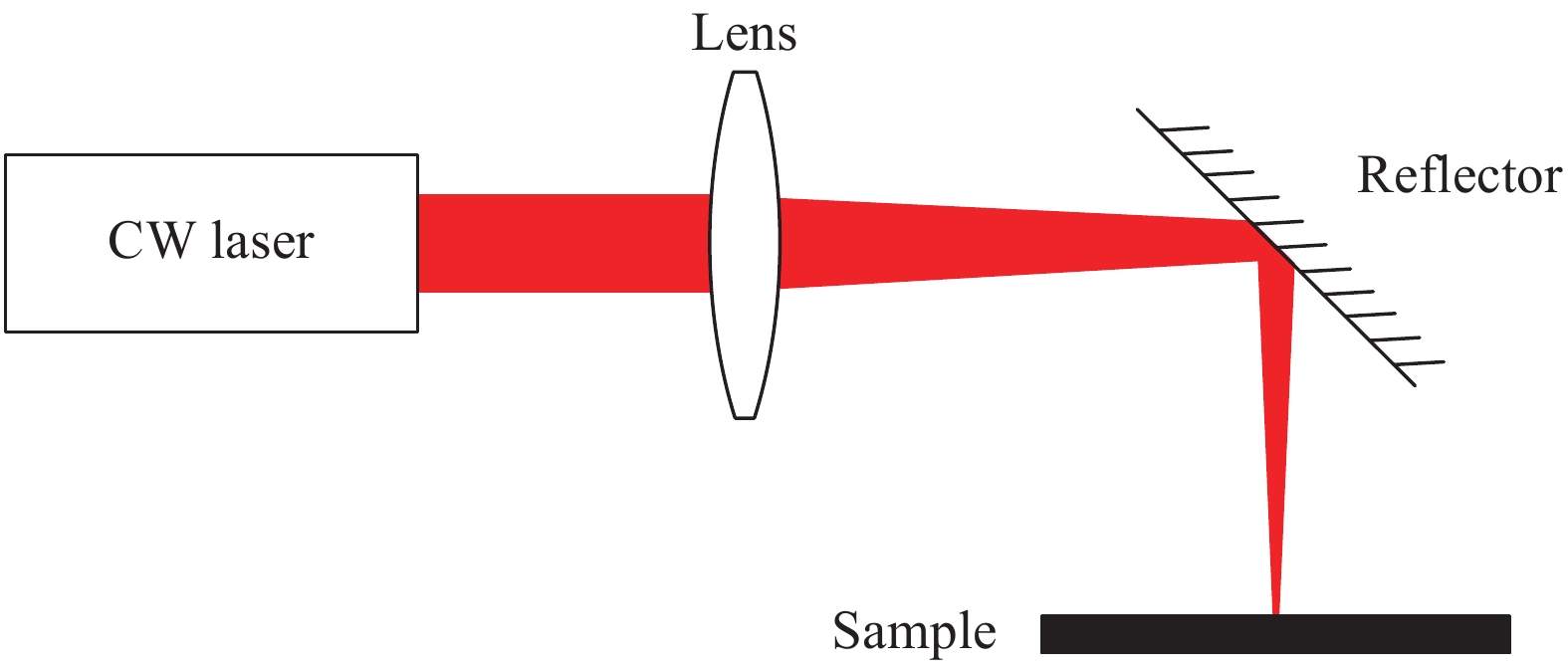
图 1 激光辐照太阳能电池实验光路示意图
Figure 1. Diagram of the light path in experiment of laser irradiation of solar cell
-
为了获取激光辐照太阳能电池的损伤形貌,采用LBIC测量系统对激光辐照区域进行扫描。LBIC测量系统如图2所示。LBIC测量系统聚焦光斑直径约为34 μm,扫描步长为10 μm,扫描速度为1 902点/s。
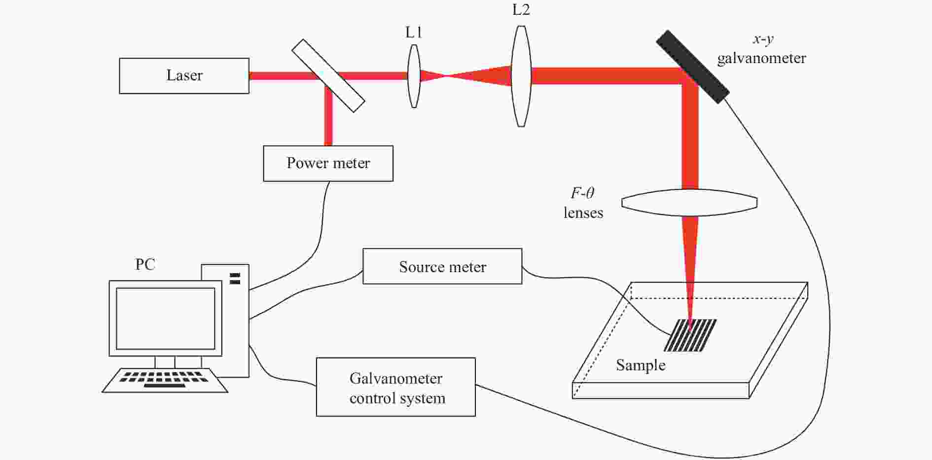
图 2 LBIC成像系统示意图
Figure 2. Diagram of LBIC mapping system
对于波长为1070 nm的辐照激光,其在晶体硅中穿透深度约为1255 μm[9],而硅太阳能电池厚度约为200 μm,远小于辐照激光的穿透深度,因此使用1070 nm激光辐照太阳能电池时,太阳能电池的整个厚度范围内都可能产生损伤。为了表征不同深度下太阳能电池的损伤情况,分别采用650 nm和980 nm波长激光作为LBIC系统的探测光,对太阳能电池激光辐照区域进行扫描。其中,波长为650 nm的探测光穿透深度约为4 μm,用于表征表层损伤情况;波长为980 nm的探测光穿透深度约为109 μm,用于表征深层损伤情况[10]。
-
实验中使用的太阳能电池样品尺寸为20 mm×26 mm,厚度约为200 μm,相邻两个栅线间距约为2 mm。激光聚焦在太阳能电池栅线之间,光斑直径约为2 mm。
图3是不同功率密度激光辐照4.9 s后的表面形貌图。在图3(a)~(c)中太阳能电池表面没有发生熔融,激光辐照区域的减反膜产生了不同程度的损伤。在图3(d)、(e)中,硅太阳能电池在光斑辐照区域的中心发生了熔融,形成突起峰。在图3(e)中,太阳能电池栅线处观察到颗粒状物质,这是太阳能电池栅线材料发生熔融后再凝固形成的物质。
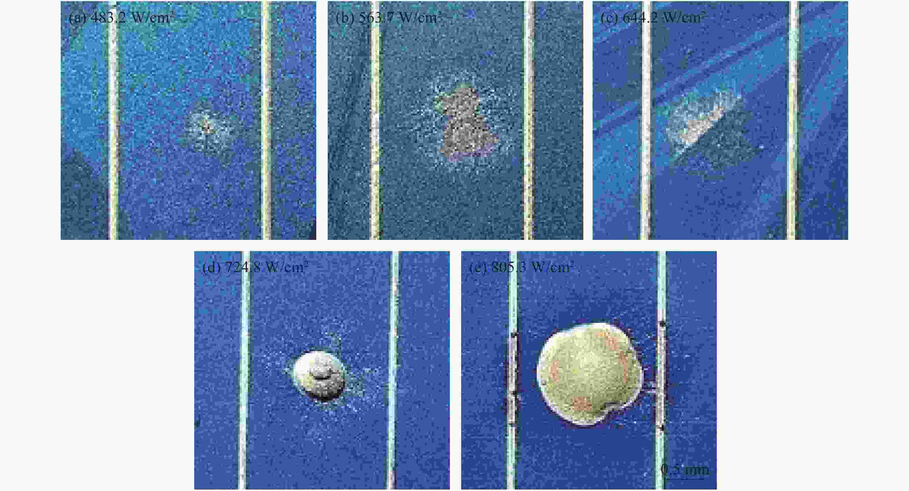
图 3 不同功率密度激光辐照后太阳能电池形貌图
Figure 3. Surface images of solar cells after laser irradiation with different power densities
对激光辐照后的太阳能电池进行暗环境伏安特性曲线测试,结果如图4所示。根据太阳能电池暗环境伏安特性曲线求解得到太阳能电池串联电阻、并联电阻[11],如表1所示。

图 4 不同功率密度激光辐照后太阳能电池暗环境伏安特性曲线图
Figure 4. Voltage-current characteristic curves of solar cells in dark environment after laser irradiation with different power densities
表 1 不同功率密度激光辐照后太阳能电池的串联电阻和并联电阻值
Table 1. Series resistance and shunt resistance of solar cells after laser irradiation with different power densities
Power density/W·cm−2 Series resistance/Ω Series resistance drop percentage Shunt resistance/Ω Shunt resistance drop percentage Before irradiation 1.35 - 6543.74 - 483.2 0.13 90.4% 5060.01 22.7% 563.7 0.17 87.4% 1747.88 73.3% 644.2 0.32 76.3% 170.33 97.4% 724.8 0.14 89.6% 643.06 90.2% 805.3 0.11 91.9% 141.10 97.8% 从图4中可以看出:激光辐照后的暗电流比辐照前的高。当功率密度为644.2 W/cm2和805.3 W/cm2时,暗电流在正向偏置电压小于0.5 V时明显高于辐照前,此时并联电阻分别下降了97.4%和97.8%(见表1)。并联电阻与太阳能电池内部漏电有关,漏电会造成短路[12],由此推测激光辐照使太阳能电池内部发生了短路。当正向偏置电压大于0.5 V时,激光辐照后的暗电流增大,原因是串联电阻减小。
从表1可以看出,相比于激光辐照前,不同功率密度激光辐照后串联电阻大幅下降,下降百分比都超过76.3%。随着功率密度的增加,串联电阻下降百分比变化较小,并联电阻下降百分比变化较大。
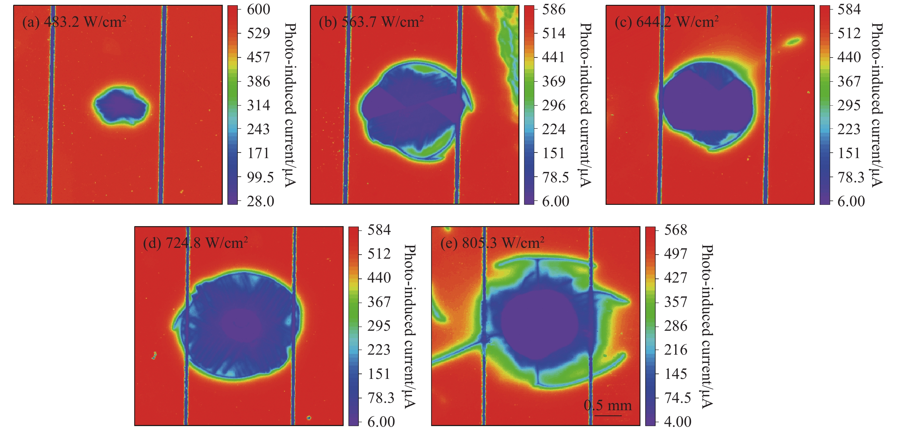
图5是LBIC系统采用650 nm波长探测光测量得到的光电流分布图。表2为图5扫描区域内电流值下降幅度表。
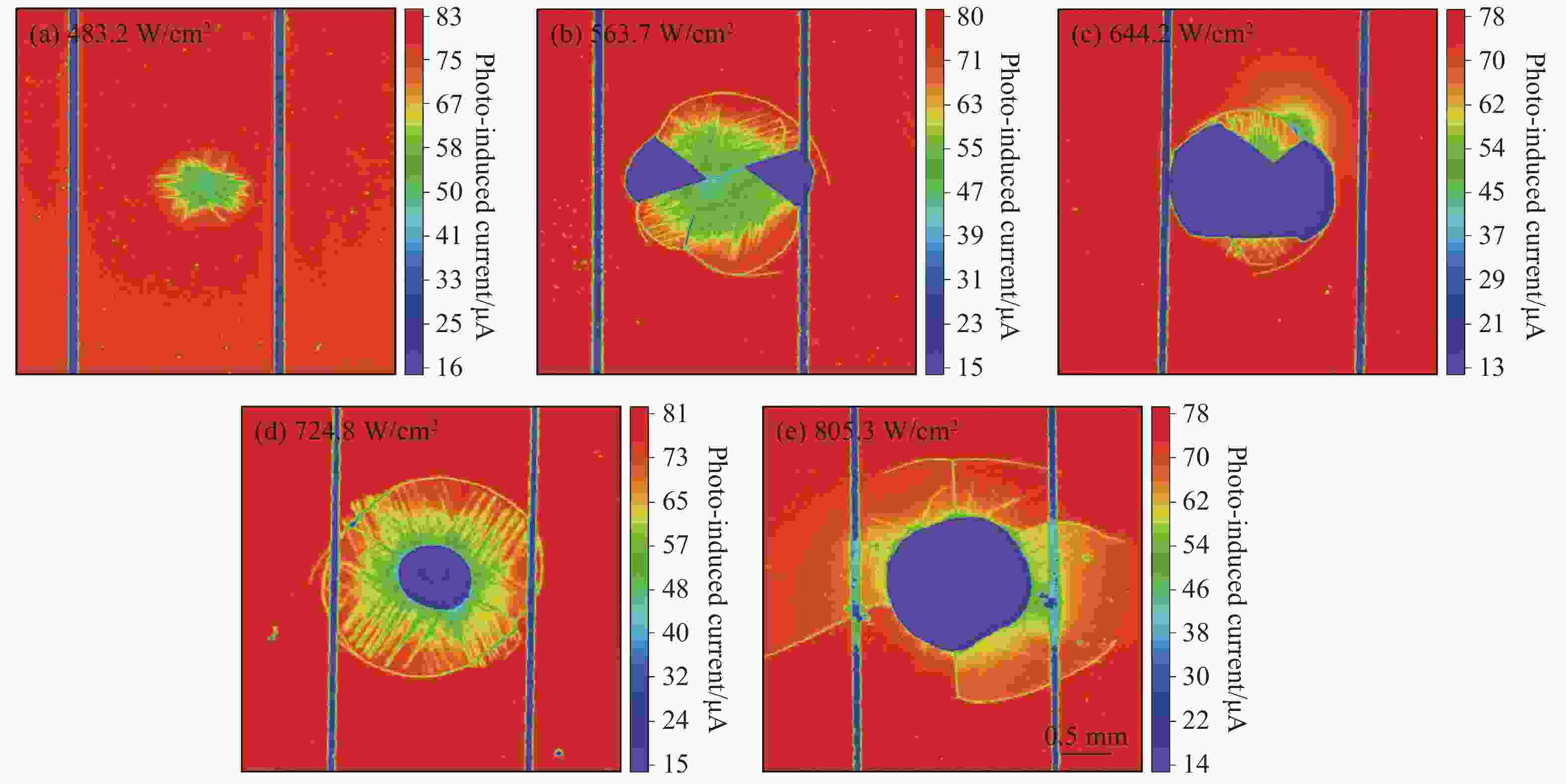
图 5 激光辐照后太阳能电池LBIC扫描结果图(650 nm)
Figure 5. 650 nm LBIC maps of solar cells after laser irradiation
表 2 不同功率密度激光辐照后太阳能电池的电流下降百分比(650 nm)
Table 2. Percentage of solar cell current drop after laser irradiation with different power densities (650 nm)
Power density/W·cm-2 Minimum current in damaged area/μA Current away from the damaged area/μA Drop percentage 483.2 54.88 77.34 29.0% 563.7 15.05 75.97 80.2% 644.2 14.14 76.05 81.4% 724.8 15.92 78.42 79.7% 805.3 14.82 75.75 80.4% 从图5(a)~(e)可以看出,激光辐照区域存在不同方向的线条,这是由于硅太阳能电池在激光辐照作用下,硅基底温升产生热应力,发生塑性形变,从而产生滑移线[13]。在图5(a)中太阳能电池激光辐照区域没有清晰的损伤边界,而图5(b)~(e)的激光辐照区域可观察到环形裂纹分界。在图5(b)中观察到了夹角为54.6°的滑移线,在图5(c)中观察到了夹角为94.4°的滑移线,在图5(d)中观察到了夹角为56.7°的滑移线。在图5(e)中,滑移线变少,这是由于激光的功率密度很大,太阳能电池发生较大面积的熔融损伤,滑移被抑制[14];同时,由于热熔融区域的应力被释放,最大拉伸应力出现在激光辐照区域周围,产生了径向裂纹[15]。
在图5(b)、(c)中,沿着滑移线方向产生裂纹,该裂纹和环向裂纹相交,导致产生低光电流区域,电流下降值超都过79.7%(见表2),可以认为该区域的太阳能电池已经失效。在图5(d)、(e)中,激光辐照中心发生熔融,太阳能电池结构被破坏,导致失效。同时,在图5(e)中,靠近激光辐照区域的栅线熔断,没有了栅线的遮挡,探测光能够入射到太阳能电池内部,因此靠近损伤区域的栅线处光电流比远离损伤处的高。
在图5(c)、(e)中,失效区域面积与并联电阻下降百分比一样明显大于其他太阳能电池,由此推测并联电阻的变化与失效太阳能电池区域面积有关。
图6是LBIC系统采用980 nm波长探测光测量得到的光电流分布图。在图6(a)~(e)中,激光辐照区域内滑移线的分布变得模糊,整个损伤区域内的光电流呈现出不同程度的下降,而在图5中,损伤区域内有的位置的电流值没有产生下降,原因是650 nm波长探测光只能探测到表层缺陷,而980 nm波长探测光的探测深度更深,能够探测到太阳能电池深层缺陷,由此认为太阳能电池首先发生在内部产生损伤。与此同时,在图6(b)~(e)中,环向裂纹外围附近能够明显地看到光电流衰减的现象,这是因为环向裂纹处形成了复合中心,越靠近复合中心,少数载流子复合机率增加,导致光电流下降。
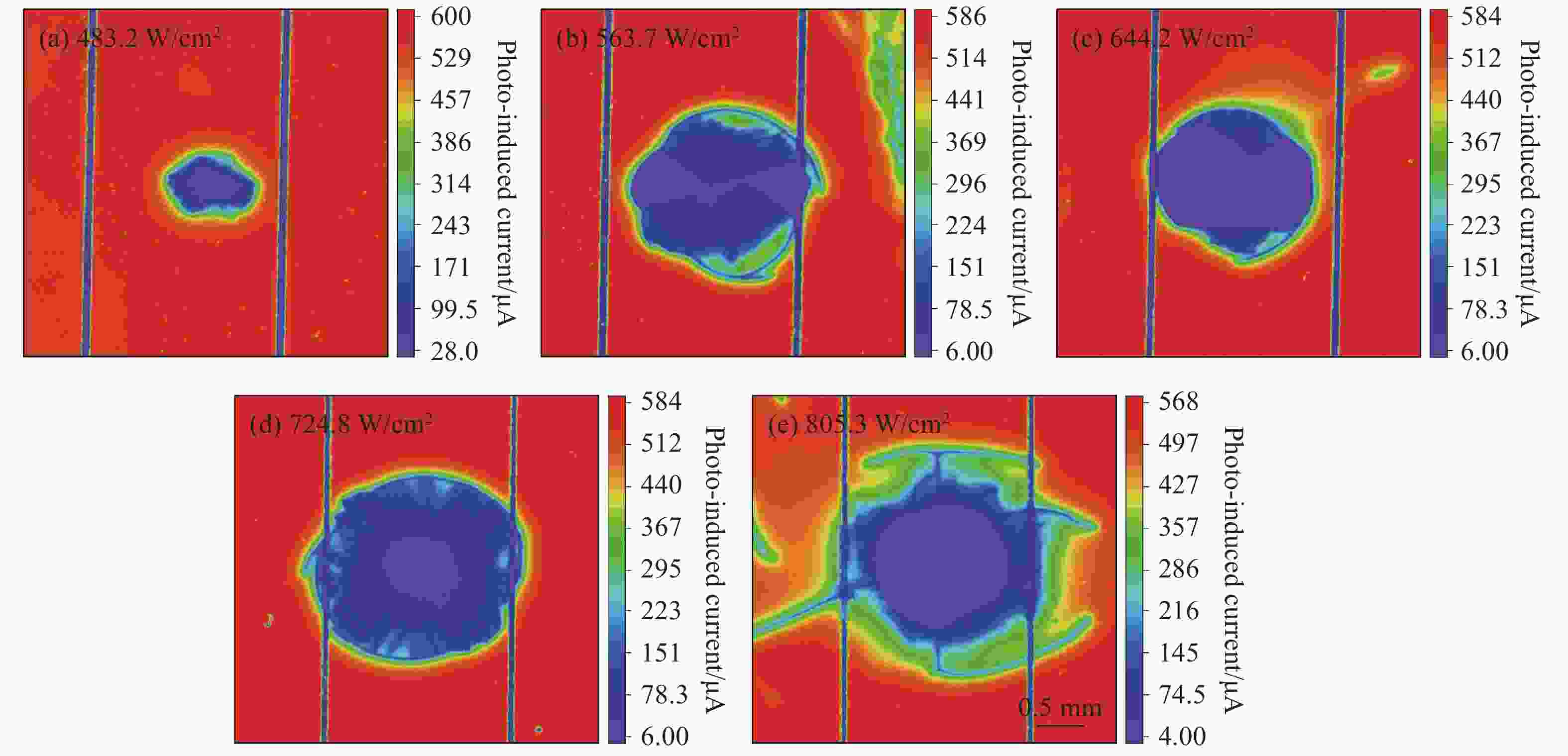
图 6 激光辐照后太阳能电池LBIC扫描结果图(980 nm)
Figure 6. 980 nm LBIC maps of solar cells after laser irradiation
根据图6计算得到不同功率密度辐照下太阳能电池损伤区域面积,如表3所示,太阳能电池损伤面积随功率密度增加而增加。当功率密度为724.8 W/cm2时,太阳能电池损伤区域面积为3.39 mm2,此时损伤面积与激光辐照面积大小基本相等;当功率密度为805.3 W/cm2时,太阳能电池损伤面积大于激光光斑。
表 3 不同功率密度激光辐照后太阳能电池损伤区域面积(980 nm)
Table 3. Damaged area of solar cells after laser irradiation with different power densities(980 nm)
Power density/W·cm-2 Damage area/mm2 Percentage of damaged area in spot area 483.2 0.57 18.2% 563.7 2.74 87.2% 644.2 2.32 73.7% 724.8 3.39 107.8% 805.3 5.08 161.9% -
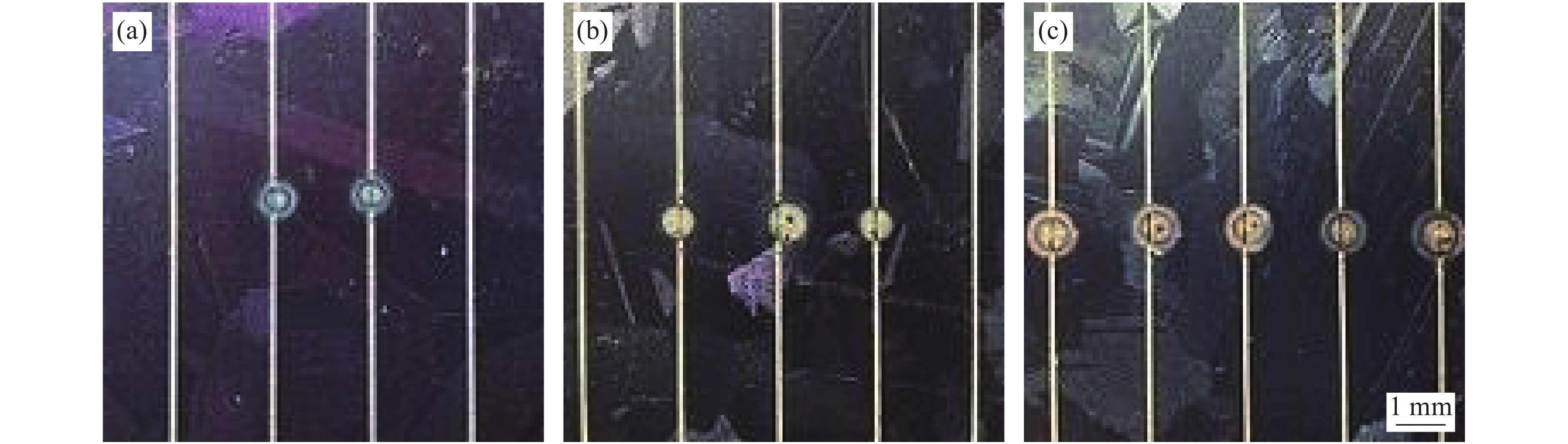
实验中使用的太阳能电池样品尺寸为16 mm×26 mm,厚度约为200 μm,相邻两个栅线间距约为2 mm。激光聚焦在太阳能电池栅线上,光斑直径约为0.5 mm。
图7是功率密度为805.3 W/cm2的激光辐照硅太阳能电池栅线0.5 s后的表明形貌图。图7(a)~(c)分别是激光辐照相邻两条、三条和五条栅线的实物图。从图7可以看出,激光辐照处的栅线产生了熔断,同时观察到了栅线凹槽和球状颗粒。
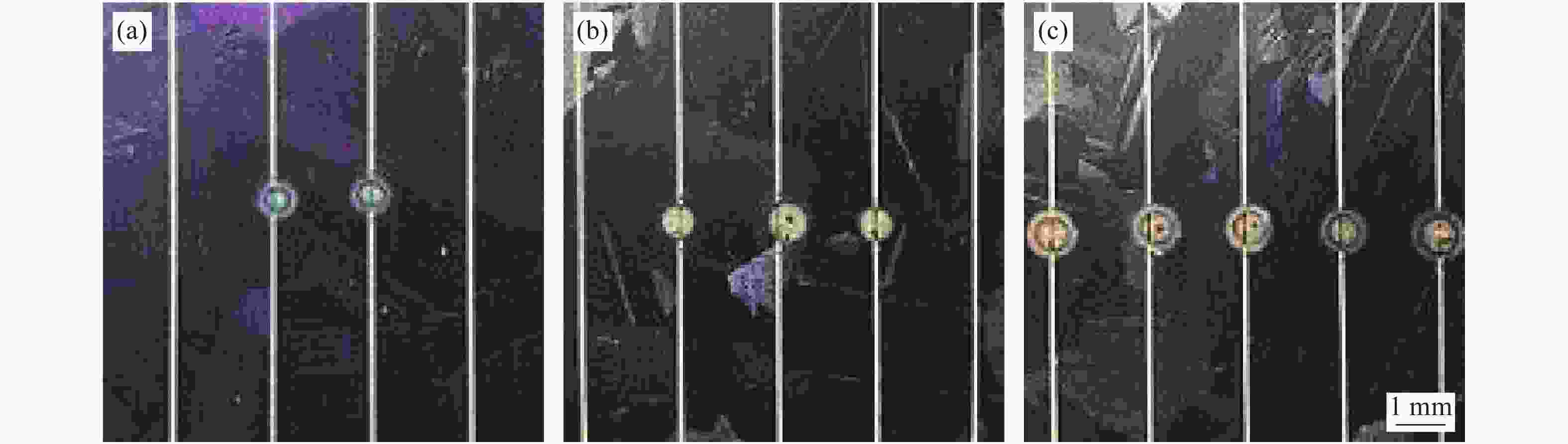
图 7 激光辐照太阳能电池栅线实物图。(a)相邻两条栅线,(b)相邻三条栅线,(c)相邻五条栅线
Figure 7. Surface images of solar cells after laser irradiation on fingers. Two (a), three (b), and five (c) adjacent fingers
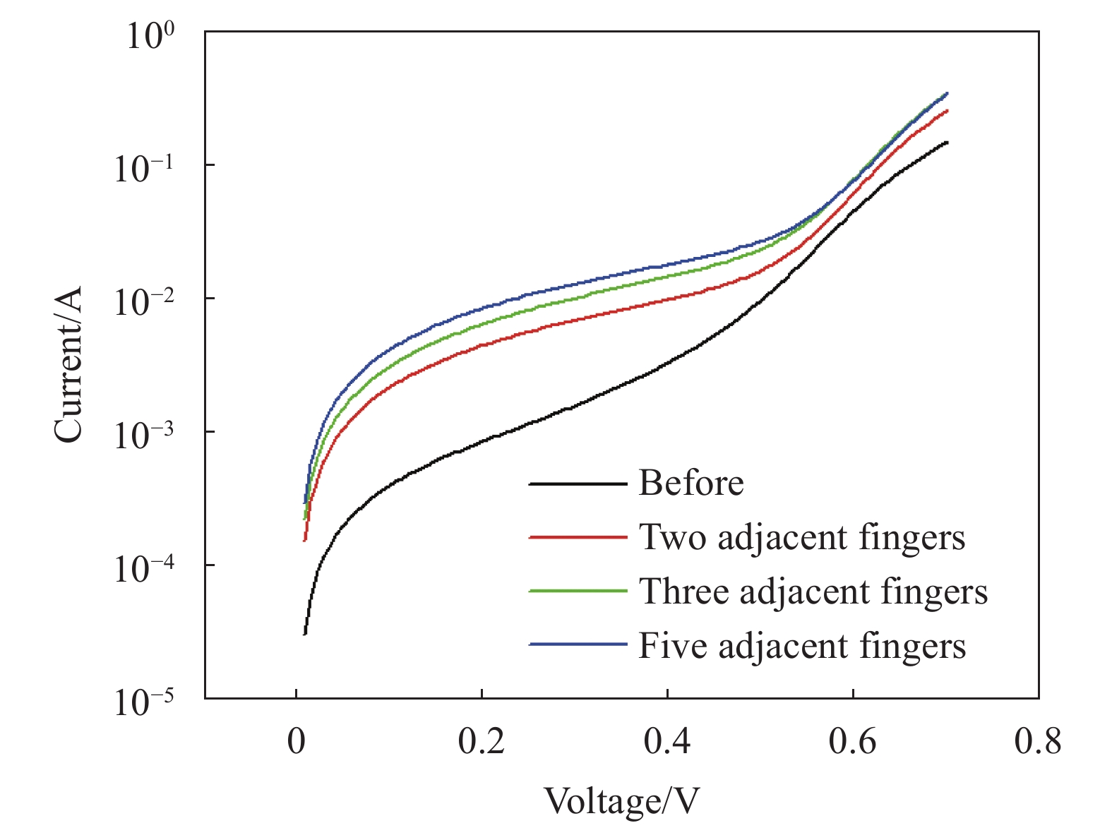
对激光辐照后的太阳能电池进行暗环境伏安特性曲线测试,结果如图8所示。激光辐照栅线后太阳能电池串联电阻值和并联电阻值如表4所示。由图8可以看出激光辐照后的太阳能电池暗电流比辐照前的暗电流明显增加。由表4可得,串联电阻和并联电阻的下降百分比近似相等,当激光辐照相邻五条栅线时串联电阻和并联电阻变化最大,分别下降了83.7%和79.7%。
图9是图7对应的光电流分布图,其中LBIC探测光源波长为650 nm,太阳能电池电极引线位于LBIC扫描图像的下侧。表5是激光辐照太阳能电池栅线导致的太阳能电池光电流下降百分比。
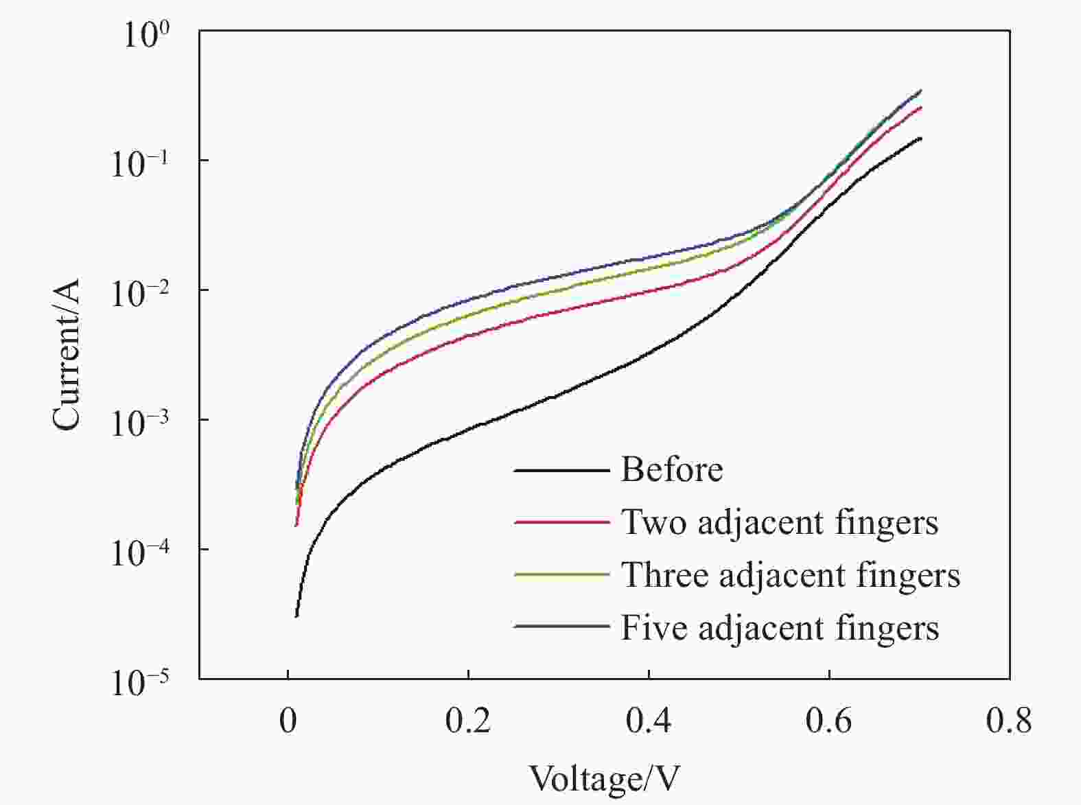
图 8 激光辐照栅线后暗环境太阳能电池伏安特性曲线图
Figure 8. Voltage-current characteristic curves of solar cell in dark environment after laser irradiation on fingers
表 4 激光辐照太阳能电池栅线后串联电阻和并联电阻值
Table 4. Series resistance and shunt resistance of solar cells after laser irradiation on fingers
Irradiation position Series resistance/Ω Series resistance drop percentage Shunt resistance/Ω Shunt resistance drop percentage Before 0.40 - 299.82 - Two adjacent fingers 0.17 57.5% 94.66 68.4% Three adjacent fingers 0.08 80.0% 76.35 74.5% Five adjacent fingers 0.07 82.5% 53.18 82.3% 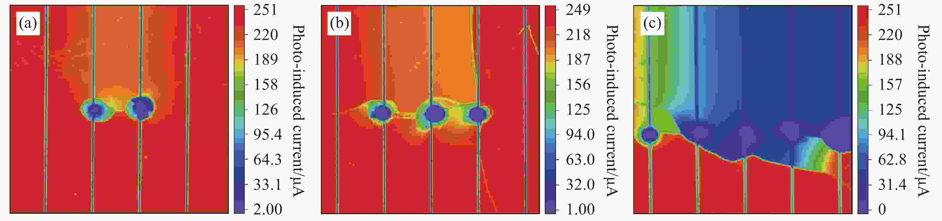
图 9 激光辐照栅线后太阳能电池LBIC扫描分布图(650 nm)。(a)相邻两条栅线,(b)相邻三条栅线,(c)相邻五条栅线
Figure 9. 650 nm LBIC maps of solar cell after laser irradiation on fingers. Two (a), three (b), and five (c) adjacent fingers
表 5 激光辐照太阳能电池栅线后电流下降百分比(650 nm)
Table 5. Percentage of solar cell current drop after laser irradiation on fingers (650 nm)
Irradiation position Current on the side away from the electrode lead/μA Current on the side close to the electrode lead/μA Drop percentage Two adjacent fingers 207.77 243.92 14.8% Three adjacent fingers 198.97 232.73 14.5% Five adjacent fingers 40.57 243.96 83.4% 在图9(a)、(b)中,太阳能电池激光辐照处远离电极引线一侧(图像上侧)出现电流值下降,原因是激光辐照使太阳能电池栅线发生熔断,远离电极引线一侧的载流子收集效率降低,从而导致光电流下降。在图9(c)中,由于激光多次辐照,太阳能电池产生裂纹,导致太阳能电池远离电极引线一侧的电流值下降了83.4%,产生失效。
-
研究了1070 nm连续激光辐照硅太阳能电池栅线以及栅线之间对太阳能电池的损伤情况,通过LBIC测量系统得到了太阳能电池辐照区域的光电流分布图,发现在激光辐照区域内,光电流呈现出不同程度的下降。
激光辐照太阳能电池非栅线部位时,随着功率密度的增加,太阳能电池内部首先发生损伤,然后向表面扩展。在太阳能电池表面熔融前,其内部已经产生了失效区域,失效区域的电流值下降超过76.5%。当功率密度较低时,太阳能电池主要发生应力损伤,产生裂纹。当功率密度较高时,太阳能电池发生熔融损伤,导致太阳能电池结构被破坏。熔融和裂纹导致太阳能电池内部发生短路,从而导致太阳能电池出现失效区域。相比于激光辐照前,不同功率密度激光辐照后串联电阻值大幅下降,下降百分比都超过76.3%,而并联电阻值变化与失效区域面积有关。随着功率密度的增加,串联电阻值下降百分比变化较小,并联电阻值下降百分比变化较大。此外,太阳能电池损伤面积随功率密度增加而增加。
当激光以高功率密度辐照太阳能电池栅线时,太阳能电池栅线发生熔断,辐照位置远离电极引线一侧的电流值下降超过14.5%,严重时太阳能电池产生垂直于栅线的裂纹,使远离电极引线一侧失效。激光辐照栅线部位导致串联电阻值和并联电阻值的下降百分比近似相等。
Light beam induced current mapping to characterize damage characteristics of silicon solar cell irradiated by continuous-wave laser
-
摘要: 针对连续激光辐照硅太阳能电池的损伤特性,采用光束诱导电流(LBIC)成像方法进行表征,并对其毁伤特性进行了分析。首先采用波长为1 070 nm的连续激光聚焦在硅太阳能电池表面,诱导太阳能电池产生损伤,再通过LBIC系统扫描得到激光辐照区域的光电流分布图,进而分析太阳能电池的损伤情况。为了表征不同深度下太阳能电池的损伤情况,LBIC测量系统分别采用650 nm和980 nm波长激光作为探测光源。结果表明,1 070 nm连续激光辐照硅太阳能电池非栅线部位时,太阳能电池损伤首先发生在内部;随着功率密度的增加,在太阳能电池表面熔融前,电池内部已经产生了失效区域。当激光辐照太阳能电池栅线时,栅线会发生熔断,导致辐照位置远离电极引线一侧的光电流下降;严重时会使太阳能电池产生垂直于栅线的裂纹,使远离电极引线一侧的电池失效。该研究成果可为连续激光辐照太阳能电池损伤机理研究提供参考。Abstract: Aiming at the damage characteristics of silicon solar cells irradiated by continuous-wave (CW) laser, a light beam induced current (LBIC) mapping system was applied to characterize the damage characteristics of solar cells, and the damage characteristics were analyzed. A 1 070 nm CW laser was used to focus on the surface of silicon solar cell to induce damage. A LBIC system was use to obtain the photocurrent spatial distribution of the laser irradiation area of solar cell to analyze the damage. In order to characterize the damage of solar cell at different depths, the LBIC system used 650 nm and 980 nm lasers as probe light sources respectively. The results show that when 1 070 nm CW laser irradiates the non-finger part of a silicon solar cell, the solar cell damage first occurs inside; with the increase of power density, there is an invalid region inside the solar cell before its surface melts. When the laser irradiates fingers, the finger will melting. It will result in a decrease in the photocurrent at the side of the irradiated position which away from the electrode lead. In severe cases, the solar cell will have cracks which perpendicular to fingers, and the cracks will invalidate the cell on the side away from the electrode lead. The results can provide a reference for the research on the damage mechanism of CW laser irradiated solar cells.
-
图 1 激光辐照太阳能电池实验光路示意图
Figure 1. Diagram of the light path in experiment of laser irradiation of solar cell
图 3 不同功率密度激光辐照后太阳能电池形貌图
Figure 3. Surface images of solar cells after laser irradiation with different power densities
图 4 不同功率密度激光辐照后太阳能电池暗环境伏安特性曲线图
Figure 4. Voltage-current characteristic curves of solar cells in dark environment after laser irradiation with different power densities
图 5 激光辐照后太阳能电池LBIC扫描结果图(650 nm)
Figure 5. 650 nm LBIC maps of solar cells after laser irradiation
图 6 激光辐照后太阳能电池LBIC扫描结果图(980 nm)
Figure 6. 980 nm LBIC maps of solar cells after laser irradiation
图 7 激光辐照太阳能电池栅线实物图。(a)相邻两条栅线,(b)相邻三条栅线,(c)相邻五条栅线
Figure 7. Surface images of solar cells after laser irradiation on fingers. Two (a), three (b), and five (c) adjacent fingers
图 8 激光辐照栅线后暗环境太阳能电池伏安特性曲线图
Figure 8. Voltage-current characteristic curves of solar cell in dark environment after laser irradiation on fingers
图 9 激光辐照栅线后太阳能电池LBIC扫描分布图(650 nm)。(a)相邻两条栅线,(b)相邻三条栅线,(c)相邻五条栅线
Figure 9. 650 nm LBIC maps of solar cell after laser irradiation on fingers. Two (a), three (b), and five (c) adjacent fingers
表 1 不同功率密度激光辐照后太阳能电池的串联电阻和并联电阻值
Table 1. Series resistance and shunt resistance of solar cells after laser irradiation with different power densities
Power density/W·cm−2 Series resistance/Ω Series resistance drop percentage Shunt resistance/Ω Shunt resistance drop percentage Before irradiation 1.35 - 6543.74 - 483.2 0.13 90.4% 5060.01 22.7% 563.7 0.17 87.4% 1747.88 73.3% 644.2 0.32 76.3% 170.33 97.4% 724.8 0.14 89.6% 643.06 90.2% 805.3 0.11 91.9% 141.10 97.8%  下载: 导出CSV
表 2 不同功率密度激光辐照后太阳能电池的电流下降百分比(650 nm)
Table 2. Percentage of solar cell current drop after laser irradiation with different power densities (650 nm)
Power density/W·cm-2 Minimum current in damaged area/μA Current away from the damaged area/μA Drop percentage 483.2 54.88 77.34 29.0% 563.7 15.05 75.97 80.2% 644.2 14.14 76.05 81.4% 724.8 15.92 78.42 79.7% 805.3 14.82 75.75 80.4%
下载: 导出CSV
表 3 不同功率密度激光辐照后太阳能电池损伤区域面积(980 nm)
Table 3. Damaged area of solar cells after laser irradiation with different power densities(980 nm)
Power density/W·cm-2 Damage area/mm2 Percentage of damaged area in spot area 483.2 0.57 18.2% 563.7 2.74 87.2% 644.2 2.32 73.7% 724.8 3.39 107.8% 805.3 5.08 161.9%
下载: 导出CSV
表 4 激光辐照太阳能电池栅线后串联电阻和并联电阻值
Table 4. Series resistance and shunt resistance of solar cells after laser irradiation on fingers
Irradiation position Series resistance/Ω Series resistance drop percentage Shunt resistance/Ω Shunt resistance drop percentage Before 0.40 - 299.82 - Two adjacent fingers 0.17 57.5% 94.66 68.4% Three adjacent fingers 0.08 80.0% 76.35 74.5% Five adjacent fingers 0.07 82.5% 53.18 82.3%
下载: 导出CSV
表 5 激光辐照太阳能电池栅线后电流下降百分比(650 nm)
Table 5. Percentage of solar cell current drop after laser irradiation on fingers (650 nm)
Irradiation position Current on the side away from the electrode lead/μA Current on the side close to the electrode lead/μA Drop percentage Two adjacent fingers 207.77 243.92 14.8% Three adjacent fingers 198.97 232.73 14.5% Five adjacent fingers 40.57 243.96 83.4%
下载: 导出CSV
-
[1] 邱冬冬, 金华松, 刘斯亮, 等. 短脉冲和连续激光对太阳能电池的损伤对比[J]. 光电子技术, 2011, 31(2): 112-116. doi: 10.3969/j.issn.1005-488X.2011.02.009 Qiu D, Jin H, Liu S, et al. Damage contrast of solar cells induced by short-pulse laser and CW Laser [J]. Optoelectronic Technology, 2011, 31(2): 112-116. (in Chinese) doi: 10.3969/j.issn.1005-488X.2011.02.009 [2] 邱冬冬, 金华松, 孙永江. 1064 nm激光对太阳能电池的损伤效应研究[J]. 激光杂志, 2013, 34(2): 23-24. doi: 10.3969/j.issn.0253-2743.2013.02.010 Qiu D, Jin H, Sun Y. Damage effects research of solar cells under the irradiation of 1064 nm CW laser [J]. Laser Journal, 2013, 34(2): 23-24. (in Chinese) doi: 10.3969/j.issn.0253-2743.2013.02.010 [3] 张宇. 半导体激光对硅太阳能电池的辐照效应研究[D]. 长沙: 国防科学技术大学, 2015. Zhang Y. Research of irradiation effects on silicon solar cells with diode laser[D]. Changsha: National University of Defense Technology, 2015. (in Chinese) [4] 周广龙, 徐建明, 陆健, 等. 连续激光对三结GaAs电池的损伤效应[J]. 激光与光电子学进展, 2017, 54(11): 111412. Zhou G, Xu J, Lu J, et al. Irradiation effect of continuous-wave laser on triple-junction GaAs solar cells [J]. Laser & Optoelectronics Progress, 2017, 54(11): 111412. (in Chinese) [5] Li G, Zhang H, Wang C, et al. Effect of 1070 nm laser intensity on parameters of In0.3Ga0.7As solar cell [J]. Chinese Optics Letters, 2019, 17(3): 66-70. [6] Tang D, Xu J, Li Y, et al. Damage effects of tri-junction GaAs solar cells irradiated by continuous-wave laser in vacuum [J]. Aerospace Shanghai (Chinese & English), 2020, 37(2): 54-60. (in Chinese) doi: 10.19328/j.cnki.1006-1630.2020.02.007 [7] Chen Y, Chang H, Zhou W, et al. Response of pulse laser irradition solar cell and effect of photoelectric conversion [J]. Infrared and Laser Engineering, 2020, 49(S1): 20200262. (in Chinese) doi: 10.3788/IRLA20200262 [8] 常浩, 陈一夫, 周伟静, 等. 纳秒激光脉冲辐照太阳能电池损伤特性及对光电转化的影响[J]. 红外与激光工程, 2021, 50(S2): 20210296. doi: 10.3788/IRLA20200296 Chang H, Chen Y, Zhou W, et al. Damage characteristics of the solar cells irradiated by nanosecond pulsed lasers and the effects on photoelectric conversion [J]. Infrared and Laser Engineering, 2021, 50(S2): 20210296. (in Chinese) doi: 10.3788/IRLA20200296 [9] Schinke C, Peest P C, Schmidt J, et al. Uncertainty analysis for the coefficient of band-to-band absorption of crystalline silicon [J]. AIP Advances, 2015, 5(6): 067168. doi: 10.1063/1.4923379 [10] Jellison G E, Budai J D, Bennett C J C, et al. High-resolution X-ray and light beam induced current (LBIC) measurements of multcrystalline silicon solar cells[C]//35 th IEEE Photovoltaic Specialists Conference, 2010. [11] Kaminski A, Marchand J J, Fave A, et al. New method of parameters extraction from dark I-V curve[C]//26 th IEEE Photovoltaic Specialists Conference, Anaheim, 1997. [12] 纳尔逊. 太阳能电池物理: [M]. 高扬, 译. 上海: 上海交通大学出版社, 2011. Nelson J. The Physics of Solar Cells[M]. Translated by Gao Yang. Shanghai: Shanghai Jiao Tong University Press, 2011. (in Chinese) [13] Li Z, Zhou J, Zhang H, et al. Anisotropic study of thermal stresses of (110) Silicon induced by millisecond laser[C]//3 rd International Symposium on Laser Interaction with Matter, 2014. [14] Jia Z, Li Z, Lv X, et al. Slip-free processing of (001) silicon wafers under 1064 nm laser ablation [J]. Applied Optics, 2017, 56(17): 4900-4904. doi: 10.1364/AO.56.004900 [15] Wang X, Zhu D H, Shen Z H, et al. Surface damage morphology investigations of silicon under millisecond laser irradiation [J]. Applied Surface Science, 2010, 257(5): 1583-1588. doi: 10.1016/j.apsusc.2010.08.098 -

 点击查看大图

计量
- 文章访问数: 332
- HTML全文浏览量: 124
- PDF下载量: 54
- 被引次数: 0

