


 下载:
下载:


-
光电跟踪系统(Acquisition, Tracking, and Pointing, ATP),是一种利用光电技术实现对目标的指向和跟踪的设备,具有测量跟踪精度高等特点,现有ATP系统通常搭载精密的光学系统和探测器,能够对目标进行精确定位、跟踪和瞄准[1]。近年来,ATP系统的跟踪目标逐渐向高速、高机动特性发展,对光电跟踪系统提出了更高的要求。由于复合轴控制技术的出现,采用粗精二级控制结构,限制ATP系统跟踪对象速度的主要因素不再是执行系统的跟踪能力[2-3]。对于高速目标跟踪系统,图像传感器反馈的时间延迟成为制约系统跟踪速度上限的主要因素[4]。图像反馈延时已经成为当前制约ATP系统跟踪带宽提高的瓶颈。
为实现高跟踪带宽,通过预测实现对信号延迟的补偿是常用的方式之一。通过预测滤波实现高性能跟踪的光电跟踪技术通常根据差分计算得到的目标轨迹,采用Kalman滤波的后验估计对目标速度信息进行校正,能一定程度上提高系统对特定目标运动形式的跟踪能力[5-6]。文献[7]提出使用Kalman滤波器进行多步迭代实现预测,利用延迟的融合目标轨迹预测目标当前时刻状态信息,但是Kalman滤波进行多步预测容易导致较大的误差,严重时会导致闭环系统震荡。另外,多项式数据拟合方法也是较为常用的目标状态估计方法,文献[8]基于正交多项式原理,根据历史状态信息拟合曲线,实现对目标的运动状态估计,不再需要目标模型的先验估计,改善传统的最小二乘拟合算法存在的法方程病态导致计算精度变差的问题,但是算法精度比Kalman滤波器低,并且需要根据不同场景选择不同的参数。另外交互式多模型算法引入,有效解决了目标模型不确定性的问题[9-10],能够更好地对随机运动的目标实现跟踪。但多模型提高估计精度的同时,也伴随着计算量变大的问题,并且模型之间的融合交互规律也难以确定。另外,构造目标模型集所需的先验知识一般也很难获取,也限制了该方法在工程中的应用。文献[11]提出使用支持向量机对目标运动模型进行分类,该方法有效解决了计算量和模型间交互策略的问题,但训练集与特征的选取还存在问题。针对跟踪时模型不确定性的问题,相关学者采用鲁棒状态估计[12]进行目标运动状态预测,针对光电跟踪系统跟踪目标轨迹的时延问题进行建模,应用到基于预测滤波的光电跟踪技术当中,也取得了一定的效果。
前馈控制可以较好地解决光电跟踪系统精度与稳定性之间的矛盾问题,并且不会影响原有系统的稳定性,是最直接提升系统跟踪能力的方法。前馈控制的关键是获取目标实时准确的运动状态信息,如目标位置、速度、加速度等。然而由于图像传感器无法直接提供目标全局轨迹或者系统高阶状态信息,因此光电跟踪系统无法通过传统手段直接实现前馈控制[13]。
近年来,通过传感器融合和预测滤波技术合成目标运动信息实现等效前馈是一个重要的研究方向[14]。其中,基于Kalman滤波的预测前馈方法已经在光电系统上得到了广泛应用,并且在此基础上发展出了一系列的改进预测滤波方法[15-17]。但这种方法仍然存在一些限制,其性能依赖于目标信息的合成精度,也就是前馈运动信息的准确性,当合成的目标信息的精度较低,不仅不能提高跟踪精度,反而还可能造成系统不稳定。
文中首先将脱靶量数据和高精度编码器反馈值根据微分跟踪原理进行数据融合,获得噪声较小的目标运动状态数据;然后根据改进的CA (匀加速)模型预测,减小计算量和估计参数量,得到近似的真实目标运动状态信息;再根据预测得到的结果,结合前一时刻的结果进行最小二乘多项式拟合,实现低频信号到高频信号的扩展,并将预测扩展的数据进行前馈控制器设计,有效地提高了系统跟踪高速目标的跟踪精度。
-
本节以传统的两轴光电跟踪系统为研究对象,提出系统总体控制回路,建立数学模型,为设计改进前馈控制算法奠定基础。
-
光电跟踪系统主要由跟踪转台、伺服控制系统、光学组件等构成。光电跟踪平台结构示意图如图1所示。

图 1 光电跟踪平台结构示意图
Figure 1. Structure diagram of photoelectric tracking platform structure
跟踪转台是整个系统的核心设备,由基座、方位框架、俯仰框架组成;伺服控制系统是光电跟踪平台实现稳定跟踪控制的关键,主要由电机、驱动器、编码器、陀螺仪等组成,能够实现高精度位置、速度反馈,实现跟踪功能;光学组件是探测目标、计算位置偏差的重要部件,实现跟踪目标的实时搜索和测量,主要包括激光探测器、红外相机、可见光相机等,这些设备用途和应用环境不同,根据光电稳定平台所处环境和实际的任务需求可以进行更换,灵活性较强。
光电跟踪伺服控制系统采用速度环和位置环的双闭环控制结构,其中,速度环利用惯性陀螺仪隔离各种扰动,保证转台视轴在惯性空间指向稳定;位置环通过编码器检测转台的角位移量作为反馈信号,位置环控制器接收目标脱靶量;精跟踪补偿粗跟踪残差,从而保证转台视轴始终指向目标实现跟踪目标的目的。其控制结构如图2所示。

图 2 光电跟踪系统控制结构
Figure 2. Control structure of photoelectric tracking system
-
直流力矩电机和负载采用同轴方式刚性连接,这种连接结构简单,维护简便,系统的传动效率更高,系统的增益和带宽得到提高,低速的平稳性较好,对保证系统的稳定性和精度有促进作用。直流力矩电机的电枢回路电压平衡方程式为:
$$ \left\{ \begin{gathered} {E_{\text{a}}} = {K_e}\omega \\ {U_{\text{a}}} = {R_a}{i_a} + {L_a}\frac{{{\rm{d}}{i_a}}}{{{\rm{d}}t}} + {E_a} \\ \end{gathered} \right. $$ (1) 式中:
${E_a}$ 为电机电枢反电势,单位为V;${K_{\text{e}}}$ 为电机反电势系数,单位为V/rad·s−1;$\omega $ 为电机角速度,单位为rad/s;${U_a}$ 为电机控制电压,单位为V;${R_a}$ 为电机电枢电阻,单位为Ω;${i_a}$ 为电机电枢电流,单位为A;${L_a}$ 为电机电枢电感,单位为H。直流力矩电机的电磁转矩方程式为:$$ {T_d} = {K_t}{i_a} $$ (2) 式中:
${T_d}$ 为电机电磁转矩,单位为N·m;${K_t}$ 为电机转矩系数,单位为N·m/A。直流力矩电机系统的转矩平衡方程式为:$$ J\frac{{{\rm{d}}\omega }}{{{\rm{d}}t}} = {T_d} - {T_f} $$ (3) 式中:
$J$ 为电机轴上承受的总转动惯量,单位为kg·m2;${T_f}$ 为扰动力矩,单位为N·m。对公式(3)进行拉氏变换得:
$$ \left\{ \begin{gathered} {E_a}(s) = {K_e}\omega (s) \\ {U_a}(s) = {R_a}{i_a}(s) + {L_a}s{i_a}(s) + {E_a}(s) \\ {T_d}(s) = {K_t}{i_a}(s) \\ Js\omega (s) = {T_d}(s) - {T_f}(s) \\ \end{gathered} \right. $$ (4) 以电机两端加载的电压为输入,以角速度为输出,得到直流力矩电机的传递函数模型如图3所示。

图 3 直流力矩电机模型
Figure 3. DC torque motor model
-
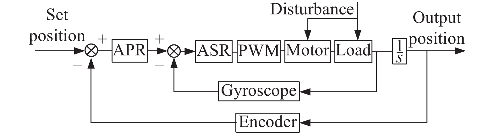
光电跟踪平台的俯仰轴与方位轴互相垂直,伺服系统组成也基本相同。图4为单轴控制系统框图。伺服系统中位置环仅能抑制低频扰动,速度环对外界扰动抑制更加明显,是提高系统性能的关键[18]。并根据电机数学模型设计速度环PI控制器和位置环PI控制器,保证系统能够快速稳定地跟踪目标。但是负反馈闭环回路基本原理是根据误差进行补偿控制,因此一定存在延迟问题,在引入延迟较高的图像闭环回路后,系统的跟踪能力会大幅下降。

图 4 单轴控制系统框图
Figure 4. Block diagram of single axis control system
解决上述问题最有效的手段是进行前馈控制,相当于“预判”目标运动,从而提前使得系统到达指定位置 ,补偿跟踪延迟,提高响应速度。因此设计合理的跟踪前馈控制方法是实现高性能跟踪的有效途径。
-
文中提出一种基于传感器融合预测的改进跟踪前馈控制方法。首先将高精度编码器反馈值与图像反馈脱靶量时钟对齐,融合获得带有滞后的目标运动状态信息;再根据改进CA模型进行Kalman预测,补偿图像延迟,输出速度前馈量;然后根据最小二乘多项式拟合原理拟合进行数据扩展,获得与控制频率相符合的位置数据,从而实现预测控制器设计以及跟踪补偿控制回路的搭建,大幅减小由于图像反馈延迟导致的跟踪误差。该方法流程如图5所示。

图 5 基于传感器融合预测的改进跟踪前馈控制流程
Figure 5. Improved tracking feedforward control flow chart based on sensor fusion prediction
-
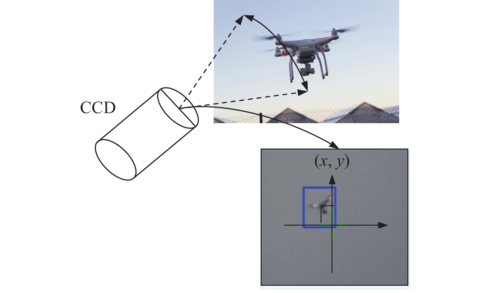
光电跟踪系统中,CCD相机根据目标在视场中的位置和判断当前目标和视轴中心的偏差像素数,然后根据光学成像的换算关系给出目标的相对角度偏差,只能给出带有延时的位置偏差量,其原理如图6所示。
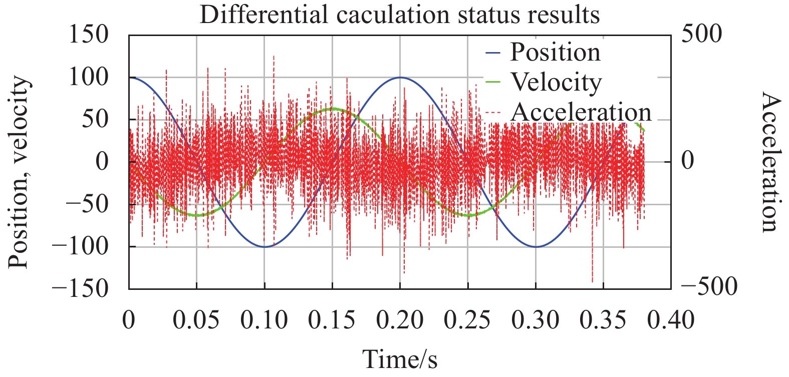
在实际系统中,通常通过差分的方式获得高阶运动信息,但是随着差分时间减小,差分导致的噪声放大作用也会随之加剧,严重时会淹没数据,差分结果如图7所示,差分得到的加速度在采样频率较高的情况下噪声已经完全淹没数据,因此传统融合方法难以获得精度较高的高阶运动信息。
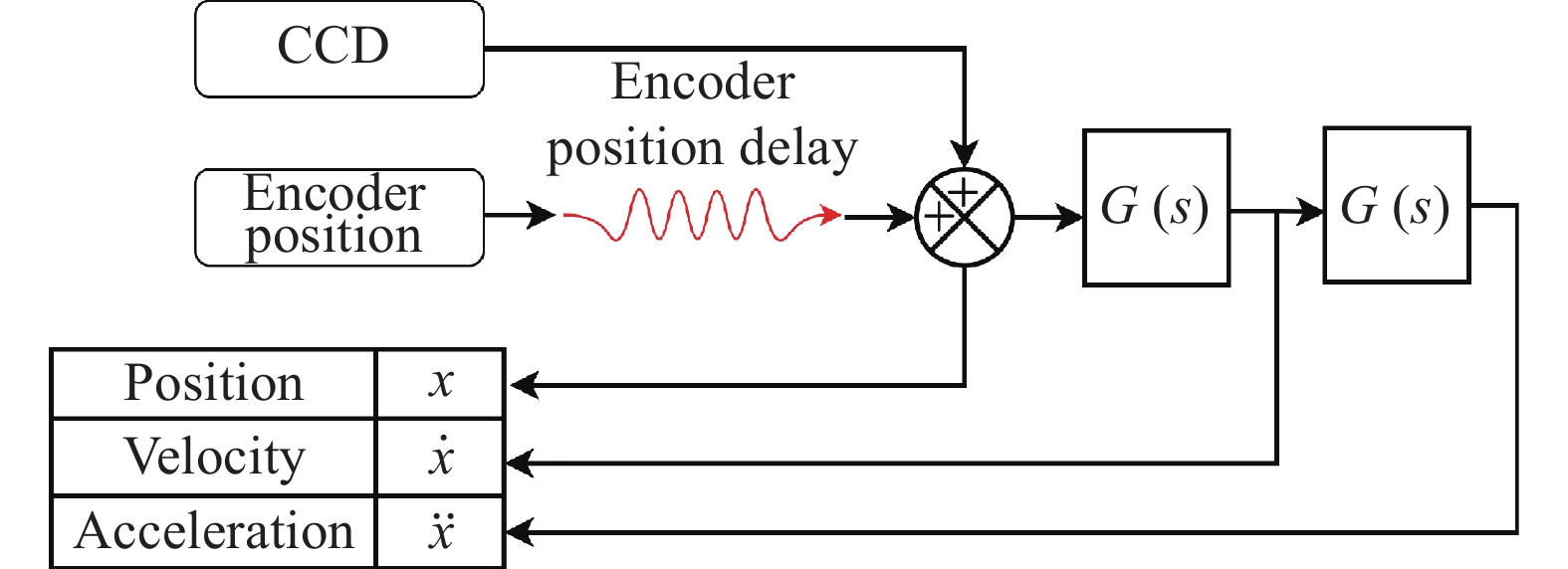
根据微分跟踪原理,提出一种传感器数据融合方法,获得目标高阶运动状态信息,为目标运动状态预测提供更多信息,提高预测准确率。构造如图8所示传感器融合策略。其中
$ G\left(s\right) $ 表示微分跟踪器传递函数,$ r $ 为滤波系数,$ r $ 越大,微分跟踪效果越好,对噪声抑制效果就越差,实际系统需根据需求选择适当的$ r $ 以平衡微分跟踪速度和滤波的效果。其中
$$ G\left( s \right) = \frac{{{r^2}s}}{{{s^2} + 2rs + {r^2}}} $$ (5) 
图 6 光电跟踪系统图像反馈原理
Figure 6. Image feedback principle of photoelectric tracking system

图 7 差分计算状态结果
Figure 7. Differential calculation status results

图 8 传感器融合策略
Figure 8. Sensor fusion strategy
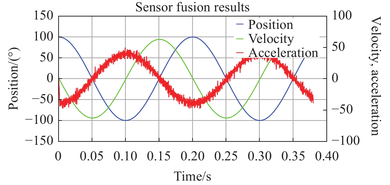
根据传感器融合策略搭建仿真模型验证融合策略结果,仿真结果如图9所示。

图 9 传感器融合结果
Figure 9. Sensor fusion results
经分析,差分获得状态信息中,速度均方根误差为5.05,加速度均方根误差为126.73;融合后速度均方根误差为0.51,加速度均方根误差为4.62,通过微分跟踪器获得目标运动状态曲线能够显著的抑制差分导致的噪声。
-
CA模型是将目标加速度的变化率视为一种干扰噪声,由于跟踪目标为高速无人机,在相邻图像帧之间加速度不会有较大变化,因此该模型不会对高速目标跟踪产生较大影响。并根据传感器数据融合获得的高阶运动信息对目标状态进行校正,保证目标预测的精度。在连续时间系统中,其对应的状态向量为:
$$ {\boldsymbol{X}}(t) = {\left[ {\begin{array}{*{20}{c}} {x(t)}&{\dot x(t)}&{\ddot x(t)} \end{array}} \right]^{\rm{T}}} $$ (6) 状态方程可以表示为:
$$ \dot {\boldsymbol{X}}(t) = {\boldsymbol{AX}}(t) + \left[ {\begin{array}{*{20}{c}} 0\\ 0\\ 1 \end{array}} \right]w(t) $$ (7) 式中:
$ \omega \left(t\right) $ 为高斯白噪声。$ A $ 对应的矩阵为:$$ A = \left( {\begin{array}{*{20}{c}} 0&1&0 \\ 0&0&1 \\ 0&0&0 \end{array}} \right) $$ (8) 离散化后的系统的状态方程为:
$$ X(k + 1) = F(k)X(k) + W(k) $$ (9) 系统状态转移矩阵F为:
$$ F = {e^{AT}} = \left[ {\begin{array}{*{20}{c}} 1&T&{{T^2}/2} \\ 0&1&T \\ 0&0&1 \end{array}} \right] $$ (10) 根据CA模型定义,在相同时间间隔
$ T=0.01 \;{\rm{s}} $ 时,目标位置和速度均和加速度成线性相关关系,即:$$ \begin{split} &X(t) = \frac{{\dot X(t)}}{2} \times T \\ & X(t) = \ddot X(t) \times 0.5{T^2} \\ & \mathop X\limits^. (t) = \mathop X\limits^{..} (t) \times T \\ \end{split} $$ (11) 随机变量X和Y的相关系数为:
$$ \rho (XY) = \frac{{Cov(X,Y)}}{{\sqrt {D(X)} \sqrt {D(Y)} }} $$ (12) 式中:
$ Cov(X,Y) $ 表示随机变量$ X $ 、$ Y $ 的协方差;$ D\left(X\right) $ 、$ D\left(Y\right) $ 分别表示随机变量$ X $ 、$ Y $ 的方差。$ \left|\rho \left(XY\right)\right|=1 $ 的充要条件为$ P\left\{Y=aX+b\right\}=1 $ ,$ a $ 、$ b $ 为常数,$ a\ne 0 $ 。在相邻时间间隔内,近似将$ X\left(t\right) $ 、$ \dot{X}\left(t\right) $ 、$ \ddot{X}\left(t\right) $ 视为两两线性正相关,因此可以得出:$$ \begin{split} &Cov(X,\mathop X\limits^{..} ){\text{ = }}\sqrt {D(X)} \sqrt {D(\ddot X)} \\ & Cov(X,\mathop X\limits^. ){\text{ = }}\sqrt {D(X)} \sqrt {D(\dot X)} \\ & Cov(\mathop X\limits^. ,\mathop X\limits^{..} ){\text{ = }}\sqrt {D(\dot X)} \sqrt {D(\ddot X)} \end{split} $$ (13) 因此其对应的过程噪声的协方差矩阵为:
$$\begin{split} Q(k) =& \left[ {\begin{array}{*{20}{c}} {Cov(\mathop X\limits^{} ,\mathop X\limits^{} )}&{Cov(\mathop X\limits^{} ,\mathop X\limits^. )}&{Cov(\mathop X\limits^{} ,\mathop X\limits^{..} )} \\ {Cov(\mathop X\limits^. ,\mathop X\limits^{} )}&{Cov(\mathop X\limits^. ,\mathop X\limits^. )}&{Cov(\mathop X\limits^. ,\mathop X\limits^{..} )} \\ {Cov(\mathop X\limits^{..} ,\mathop X\limits^{} )}&{Cov(\mathop X\limits^{..} ,\mathop X\limits^. )}&{Cov(\mathop X\limits^{..} ,\mathop X\limits^{..} )} \end{array}} \right] = \\ &\left[ {\begin{array}{*{20}{c}} {{T^4}/4}&{{T^3}/2}&{{T^2}/2} \\ {{T^3}/2}&{{T^2}/2}&{{T^{}}} \\ {{T^2}/2}&{{T^{}}}&1 \end{array}} \right] \times D(\mathop X\limits^{..} ) \end{split}$$ (14) 相较于传统CA模型,过程噪声方差估计矩阵阶次降低两阶,减小运算量,并且只需要估计加速度的观测噪声,减小了需要估计的参数。
假设目标状态方程可以表示为:
$$ \left\{ \begin{gathered} X(k + 1) = F(k)X(k) + \delta (k)W(k) \\ Z(k + 1) = H(k + 1)X(k + 1) + V(k + 1) \\ \end{gathered} \right. $$ (15) 式中:
$ X\left(k\right) $ 为当前$ X\left(k\right) $ 时刻目标运动状态向量;$ F\left(k\right) $ 为目标状态从$ k $ 时刻到$ k+1 $ 时刻的状态转移矩阵;$ \delta \left(k\right) $ 为系统噪声系数矩阵;$ W\left(k\right) $ 为过程高斯白噪声,其方差为$ Q\left(k\right) $ ;$ Z\left(k+1\right) $ 为$ k+1 $ 时刻传感器观测值;$ H\left(k+1\right) $ 状态输出矩阵;$ V\left(k+1\right) $ 为观测高斯白噪声;$ R\left(k+1\right) $ 为方差。卡尔曼滤波的迭代过程如下:(1)预测状态量和状态误差协方差预测
$$ \hat X(\left. {k + 1} \right|k) = F(k)\hat X(\left. k \right|k) $$ (16) $$ P(\left. {k + 1} \right|k) = F(k)P(\left. k \right|k){F^{\rm{T}}}(k) + Q(k) $$ (17) (2)计算卡尔曼增益
$$ S(k + 1) = H(k + 1)P(\left. {k + 1} \right|k){H^{\rm{T}}}(k + 1) + R(k + 1) $$ (18) $$ K(k + 1) = P(\left. {k + 1} \right|k){H^{\rm{T}}}(k + 1){S^{ - 1}}(k + 1) $$ (19) (3)结合传感器测量值对预测值进行校正作为下一周期预测状态输入
$$ \begin{split} &X(\left. {k + 1} \right|k + 1) = \hat X(\left. {k + 1} \right|k)+ \\ &K(k + 1)\left[ {Z(k + 1) - \hat X(\left. {k + 1} \right|k)} \right] \end{split} $$ (20) (4)计算最终估计值的方差
$$ P(\left. {k + 1} \right|k + 1) = (I - K(k + 1) \\ H(k + 1)){P^{\rm{T}}}(\left. {k + 1} \right|k) $$ (21) 式中:
$ \widehat{X}\left(k+1 |k\right) $ 表示从$ k $ 时刻到$ k+1 $ 时刻的状态预测值;$ P\left(k+1 |k\right) $ 为协方差预测值;$ K\left(k+1 |k\right) $ 为卡尔曼增益;$ I $ 为单位矩阵。根据上述公式进行迭代,就实现对信号的Kalman滤波过程。由于卡尔曼滤波中的后验估计几乎和反馈信号相同,同样存在较高的延迟,因此将先验估计
$ \widehat{X}\left(k+1 |k\right) $ 作为卡尔曼滤波的输出,从而实现对信号延迟的预测补偿。 -
CA模型可以获得较为准确的目标位置和速度状态,但是存在数据频率低的问题,作为系统输入会引入高频震荡,因此需要对预测获得的数据进行扩展,在保证预测精度的条件下将低数据频率的预测信息扩展成高数据频率的信息以减小高频震荡。
根据拟合目标运动特性,多项式至少要包含三阶信息,因此拟合曲线至少要为三次多项式,目标多项式为:
$$ y = {a_3}{t^3} + {a_2}{t^2} + {a_1}t + {a_0} $$ (22) 为了避免求解病态方程问题以及保证拟合曲线的实时性,文中只采用当前时刻和上一时刻位置、速度信息进行拟合,将
$ \left({t}_{k},{x}_{k}\right) $ 、$ \left({t}_{k},{\dot{x}}_{k}\right) $ 、$ \left({t}_{k-1},{x}_{k-1}\right) $ 、$ \left({t}_{k-1},{\dot{x}}_{k-1}\right) $ 代入,得到如下变换:$$\left[ {\begin{array}{*{20}{c}} {{x_k}}\\ {{{\dot x}_k}}\\ {{x_{k - 1}}}\\ {{{\dot x}_{k - 1}}} \end{array}} \right] = \left[ {\begin{array}{*{20}{c}} {{t_k}^3}&{{t_k}^2}&{{t_k}}&1\\ {3{t_k}^2}&{2{t_k}}&1&0\\ {{t_{k - 1}}^3}&{{t_{k - 1}}^2}&{{t_{k - 1}}}&1\\ {3{t_{k - 1}}^2}&{2{t_{k - 1}}}&1&0 \end{array}} \right]\left[ {\begin{array}{*{20}{c}} {{a_3}}\\ {{a_2}}\\ {{a_1}}\\ {{a_0}} \end{array}} \right]$$ (23) 根据上文结果,图像采样频率定为100 Hz,因此可以将数据点替换为
$ \left(0,{x}_{k}\right) $ ,$ \left(0,{\dot{x}}_{k}\right) $ ,$ \left(-T,{x}_{k-1}\right) $ ,$ \left(-T, {\dot{x}}_{k-1}\right) $ ,$ T $ 为相邻两图像反馈时间间隔,因此上式简化为:$$ \left[ {\begin{array}{*{20}{c}} {{x_k}} \\ {\begin{array}{*{20}{c}} {{{\dot x}_k}} \\ {{x_{k - 1}}} \\ {{{\dot x}_{k - 1}}} \end{array}} \end{array}} \right] = \left[ {\begin{array}{*{20}{c}} 0&0&0&1 \\ 0&0&1&0 \\ { - {T^3}}&{{T^2}}&{ - T}&1 \\ {3{T^2}}&{ - 2T}&1&0 \end{array}} \right]\left[ {\begin{array}{*{20}{c}} {{a_3}} \\ {{a_2}} \\ {{a_1}} \\ {{a_0}} \end{array}} \right] $$ (24) 令
$$ A = \left[ {\begin{array}{*{20}{c}} {{t_k}^3}&{{t_k}^2}&{{t_k}}&1 \\ {3{t_k}^2}&{2{t_k}}&1&0 \\ {{t_{k - 1}}^3}&{{t_{k - 1}}^2}&{{t_{k - 1}}}&1 \\ {3{t_{k - 1}}^2}&{2{t_{k - 1}}}&1&0 \end{array}} \right] $$ (25) 可以求得:
$$ \left[ {\begin{array}{*{20}{c}} {{a_3}} \\ {{a_2}} \\ {{a_1}} \\ {{a_0}} \end{array}} \right] = {({A^{\rm{T}}}A)^{ - 1}}{A^{\rm{T}}}\left[ {\begin{array}{*{20}{c}} {{x_k}} \\ {\begin{array}{*{20}{c}} {{{\dot x}_k}} \\ {{x_{k - 1}}} \\ {{{\dot x}_{k - 1}}} \end{array}} \end{array}} \right] $$ (26) 将求得的多项式作为数据扩展的依据,根据ATP控制系统的控制频率和图像反馈频率倍频关系,可以得到新的时间间隔
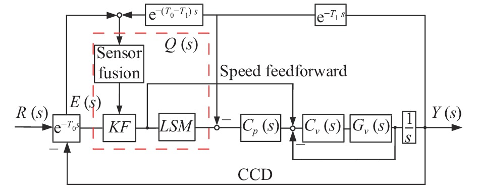
$ {T}_{s} $ ,代入上式可以得到控制系统输入的目标位置曲线。由于只用上一时刻运动数据,该方法构建的特征矩阵避免了病态方程问题,并且在减小延迟的基础上大大减小了计算量,保证数据的实时性。根据前馈控制原理,将Kalman滤波预测出的速度和拟合出的目标位置曲线,补偿到原始反馈回路中实现跟踪前馈控制。设计包含跟踪前馈的控制回路如图10所示,其中
$ {T}_{0} $ 是系统的延时,$ {T}_{1} $ 是对$ {T}_{0} $ 的测量估计延迟,$ Q\left(s\right) $ 是前馈控制器,$ {C}_{p}\left(s\right) $ 是位置控制器,$ {C}_{v}\left(s\right) $ 表示速度环控制器,$ {G}_{v}\left(s\right) $ 表示速度环被控对象。
图 10 包含跟踪前馈补偿的控制回路
Figure 10. Control loop with tracking feedforward compensation
上述系统传递函数为:
$$ \frac{{\left[ {Q\left( s \right) + C\left( s \right)} \right]{G_{}}\left( s \right){{\rm{e}}^{ - {T_0}s}}}}{{1 + C\left( s \right){G_{}}\left( s \right){{\rm{e}}^{ - {T_0}s}} + Q\left( s \right){G_{}}\left( s \right)\left( {{{\rm{e}}^{ - {T_0}s}} - {{\rm{e}}^{ - {T_1}s}}} \right)}} $$ (27) 当系统延迟
$ {T}_{0} $ 估计较为准确即$ {T}_{0}={T}_{1} $ 时,其特征方程与负反馈的特征方程相同,说明在时钟对齐的情况下,增加前馈通道不会改变系统稳定性。 -
为验证上述算法有效性和可行性,根据第一章搭建的数学模型以及设计的跟踪前馈方法搭建仿真模型进行仿真分析。
-
仿真设定CCD反馈时间间隔为0.01 s,激光ATP控制系统控制频率为5000 Hz。将输入设为:
$ y=180\mathrm{sin}\left(0.2\pi t+0.5\pi \right)-180 $ 即目标相对最大运动速度为113 (°)/s,最大加速度为71 (°)/s2,假设激光ATP作用距离为100 m以上,目标最大线速度为200 m/s,该指标覆盖大部分无人机的性能指标。 -
(1)基于CA模型融合延迟补偿结果。
采样频率为100 Hz条件预测目标运动状态如图11所示,角度偏差如图12所示。

图 11 预测状态曲线
Figure 11. Predicted state curve

图 12 预测与滞后角度偏差对比
Figure 12. Comparison of prediction and lag angle deviation
从仿真结果可以看出,在滞后10 ms之后,CCD输出的位置数据导致的误差最大值为0.628°,预测位置误差最大为0.074°误差衰减88.22%,但是位置曲线为台阶状曲线,数据频率与CCD反馈频率相同,难以复现目标位置曲线。
在5000 Hz采样频率条件下预测状态如图13所示。

图 13 高频采样预测状态偏差
Figure 13. High frequency sampling prediction state deviation error
由于预测值为台阶状,实际的位置偏差和速度偏差呈现为高频振荡的曲线,作为给定输入到控制系统中会引入高频震荡;并且角度最大偏差约为0.628°,因此,进行数据扩展是非常必要的。
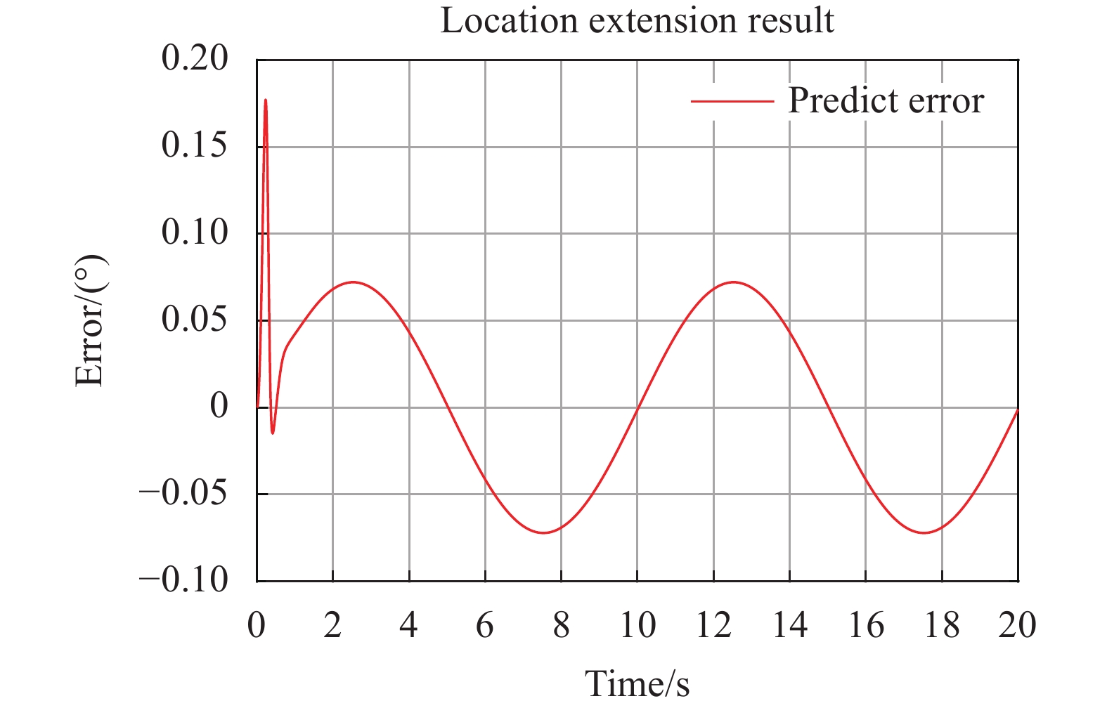
(2)基于改进最小二乘多项式拟合的数据扩展结果。
采样频率5000 Hz条件下,改进最小二乘多项式拟合数据扩展结果如图14所示,预测误差最大约为0.071°,与扩展前数据精度基本一致,并且由于数据频率较低导致的高频振荡误差几乎完全得到抑制。

图 14 位置扩展结果
Figure 14. Location extension result
(3)改进跟踪前馈控制跟踪结果。
跟踪
$ y=180\mathrm{sin}\left(0.2\pi t+0.5\pi \right)-180 $ 仿真结果如图15所示,其中基于滞后输入的跟踪误差最大为0.932°,并且由于输入信号频率较低为台阶状曲线,因此误差中叠加高频扰动;改进跟踪前馈控制回路后系统最大跟踪误差为0.072°,并且高频扰动得到了很好的抑制,跟踪误差衰减了92.27%,仿真结果表明,根据传感器融合预测的改进跟踪前馈控制方法能极大地减小系统跟踪高速目标的跟踪误差。
图 15 跟踪误差仿真结果
Figure 15. Tracking error simulation results
-
为验证上述算法有效性,搭建双轴光电跟踪平台进行实验验证。
-
实验平台主体部分由光电跟踪ATP组成,包括高精度编码器、CCD相机、图像处理板、伺服控制模块、驱动器。高精度编码器提供位置反馈,位置精度0.3″,CCD相机提供图像反馈,系统采用无刷直流电机驱动。
-
搭建光电跟踪系统,对上述内容进行实验验证,实验系统如图16所示。输入标准正弦信号作为模拟目标运动轨迹,将信号延迟10 ms后作为控制系统输入,根据上文预测滤波进行跟踪前馈补偿。

图 16 光电跟踪系统实验平台
Figure 16. Acquisition, tracking, and pointing system experimental platform
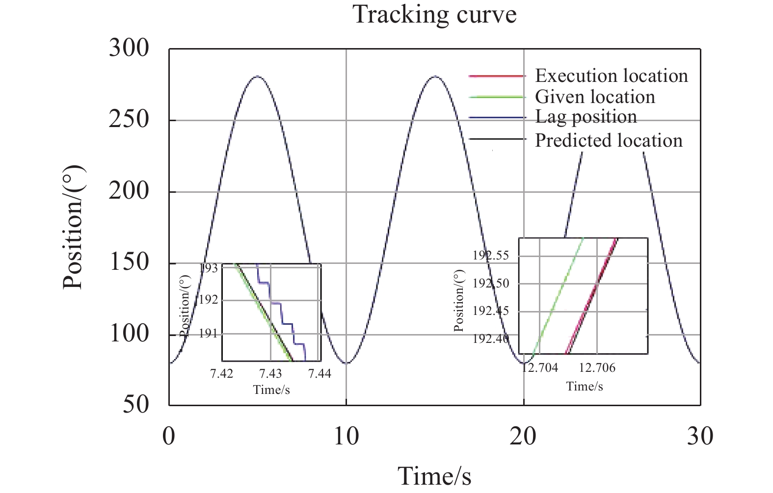
输入
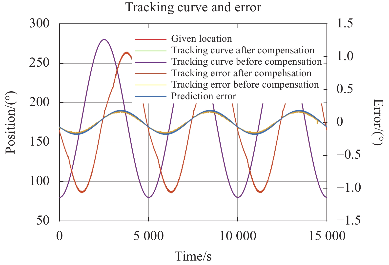
$ y=180\mathrm{sin}\left(0.2\pi t\right)+100 $ 的正弦曲线,系统输入输出及图像输出如图17所示。图像输出位置与目标真实位置存在10 ms的滞后,并且图像输出位置为台阶状曲线,根据文中进行预测及多项式差值得到的预测曲线将相位提前,并且扩充后的数据能够更好的描述目标的位置,且不会再输入信号端叠加高频扰动。系统跟踪误差如图18所示。在进行传统PID控制系统跟踪图像输入曲线时,系统最大跟踪误差为1.072°,在采用预测后建立的改进跟踪前馈控制结构后,系统最大跟踪误差降低为0.175°,提升约83.67%。对比预测补偿前后的跟踪曲线可以看出,预测后的跟踪曲线明显更接近实际目标运动位置,相比预测补偿后的结果存在相位提前,进行了延迟补偿。

图 17 跟踪曲线
Figure 17. Tracking curve

图 18 跟踪曲线及误差
Figure 18. Tracking curve and error
-
文中针对光电跟踪系统中CCD相机反馈帧率较低,延迟较大导致跟踪高速目标能力差,响应能力差的问题,提出一种基于传感器融合预测的改进跟踪前馈控制方法。
文中首先对CCD和高精度编码器进行传感器数据融合,根据微分跟踪原理对目标运动状态进行跟踪,获得目标运动的高阶信息,并大幅减小了由于差分引入的噪声问题。其次提出了一种降阶CA 模型,减小计算量和估计参数,并根据Kalman滤波原理补偿脱靶量的纯延迟环节,得到低延迟的目标运动状态信息。再次,仅结合前一时刻的结果进行最小二乘多项式拟合,避免了最小二乘中的病态矩阵问题,并能大幅减小拟合的计算量,实现CCD反馈从低频信号到高频信号的扩展。最后根据预测结果和高阶运动信息设计跟踪前馈控制回路,提高系统的响应速度,和跟踪能力。仿真结果和实验结果均表明在跟踪高速目标时,在不改变影响控制系统闭环稳定性的情况下能够将由图像滞后导致的跟踪误差大幅减小,实际试验结果补偿后跟踪误差相比补偿前跟踪误差减小约83.67%。该方法能够更为有效地补偿图像延时,提高系统控制带宽,为ATP系统的高性能跟踪控制提供了一种行之有效的思路。
Research on improved tracking feedforward control method based on sensor fusion prediction
-
摘要: 针对光电跟踪系统中CCD相机反馈帧率较低,延迟较大导致跟踪高速目标能力差、响应能力差的问题,提出一种基于传感器融合预测的改进跟踪前馈控制方法。为减小融合获得目标高阶运动状态噪声大的问题,提出一种基于微分跟踪的传感器融合策略;针对图像反馈延迟问题,提出一种降阶匀加速Kalman模型,根据融合获得的运动学信息,结合Kalman滤波进行预测跟踪,补偿脱靶量的时间延迟,得到近似真实的目标位置和速度、加速度信息;针对低频输入信号引入闭环扰动问题,提出一种快速数据扩展方法,实现低频信号到高频信号的扩展;根据传感器融合预测结果,设计跟踪前馈控制器,提高系统的响应速度。仿真结果和实验结果均表明该前馈方法能够对CCD反馈延迟导致的跟踪误差进行补偿。实验结果表明:该方法能够大幅提高系统对高速目标的跟踪性能,在目标运动状态相同条件下,相比补偿前跟踪误差减小约83.67%。Abstract:
Objective Photoelectric tracking system (Acquisition, Tracking, and Pointing, ATP) is a kind of equipment that uses photoelectric technology to realize the pointing and tracking of the target. It has the characteristics of high measurement and tracking accuracy. The existing ATP system usually carries precise optical systems and detectors, which can accurately locate, track and aim the target. For high-speed target tracking system, the time delay of sensor feedback such as image becomes the main factor that restricts the upper limit of tracking speed of the system. The delay link of system feedback has become the bottleneck restricting the improvement of ATP system's tracking ability. Therefore, an improved tracking feedforward control method is proposed based on sensor fusion prediction to solve the problem of ATP tracking high-speed targets. Methods Firstly, the CCD and high-precision encoder are fused with sensor data, and the target motion state is tracked according to the differential tracking principle to obtain the high-order information of the target motion, and the noise caused by the difference is greatly reduced. Secondly, a reduced-order CA model is proposed to reduce the computation and estimation parameters, and compensate the pure delay link of miss distance according to the Kalman filter principle to obtain the low-delay target motion state information. Thirdly, the least-squares polynomial fitting is performed only by combining the results of the previous moment, which avoids the problem of ill conditioned matrix in the least-squares, and can greatly reduce the calculation amount of fitting, and realize the expansion of CCD feedback from low frequency signal to high frequency signal. Finally, according to the prediction results and higher-order motion information, a tracking feedforward control loop is designed to improve the response speed and tracking ability of the system. Results and Discussions A new control method for ATP system to track high-speed targets is proposed. The high-order motion information of the target is obtained through sensor fusion, and the Kalman prediction based on the reduced-order CA model is carried out. The input deviation after prediction compensation is shown (Fig.12), and the error is reduced by about 88.22%; Combining the least-squares fitting at the previous moment, the problem of ill conditioned matrix in the least squares is avoided, and the expansion of data signal is realized to ensure the data stability of the system. Conclusions An improved tracking feedforward control method is proposed based on sensor fusion prediction, aiming at the problem that the feedback frame rate of CCD camera in the photoelectric tracking system is low and the delay is large, resulting in poor tracking ability and response ability of high-speed targets. The simulation results and experimental results show that the tracking error caused by image lag can be greatly reduced without changing the closed-loop stability of the control system when tracking high-speed targets. The actual test results show that the tracking error after compensation is about 83.67% less than the tracking error before compensation. This method can more effectively compensate the image delay, improve the system control bandwidth, and provide an effective idea for the high-performance tracking control of ATP system. -
图 1 光电跟踪平台结构示意图
Figure 1. Structure diagram of photoelectric tracking platform structure
图 5 基于传感器融合预测的改进跟踪前馈控制流程
Figure 5. Improved tracking feedforward control flow chart based on sensor fusion prediction
图 16 光电跟踪系统实验平台
Figure 16. Acquisition, tracking, and pointing system experimental platform
-
[1] Hu Qintao, Zhou Guozhong. Research on EMC filtering technology for electro-optics tracking equipment [J]. Foreign Electronic Measurement Technology, 2017, 36(2): 104-107. (in Chinese) [2] Ma Jiaguang, Tang Tao. Review of compound axis servomechanism tracking control technology [J]. Infrared and Laser Engineering, 2013, 42(1): 218-227. (in Chinese) [3] Xiao Yongjun, Ai Yong, Dong Ran, et al. Experiment of non-maneuvering target tracking based on ATP system [J]. Infrared and Laser Engineering, 2012, 41(9): 2439-2443. (in Chinese) [4] He Qiunong, Duan Qianwen, Zhou Xi, et al. Research progress of photoelectric tracking technology based on predictive filtering [J]. Electronic Measurement Technology, 2021, 44(9): 135-144. (in Chinese) [5] Huang Yongmei, Ma Jiaguang, Fu Chengyu. Application of forecast of moving target velocity [J]. Infrared and Laser Engineering, 2004, 33(5): 477-481. (in Chinese) [6] Tang Tao, Tian Jing, Zhong Daijun, et al. Combining charge couple devices and rate sensors for the feedforward control system of a charge coupled device tracking loop [J]. Sensors, 2016, 16(7): 968. doi: 10.3390/s16070968 [7] He Q, Luo Y, Mao Y, et al. An acceleration feed-forward control method based on fusion of model output and sensor data [J]. Sensors and Actuators A: Physical, 2018, 284: 186-193. doi: 10.1016/j.sna.2018.10.031 [8] Deng C, Mao Y, Ren W, et al. Feedforward control based on orthogonal least square for a charge-coupled device-based tracking loop[C]//IEEE 2017 Chinese Automation Congress (CAC), 2017. [9] Liu Xiaoqiang, Ren Gaohui, Xing Junzhi, et al. Simulation of application of IMM in photoelectric tracking control system [J]. Infrared and Laser Engineering, 2016, 45(9): 0917003. (in Chinese) doi: 10.3788/IRLA201645.0917003 [10] Cao Z, Mao Y, Deng C, et al. Research of maneuvering target prediction and tracking technology based on IMM algorithm[C]//8th International Symposium on Advanced Optical Manufacturing and Testing Technologies: Optical Test, Measurement Technology, and Equipment, SPIE, 2016. [11] Mao Y, He Q, Zhou X, et al. A feedforward method based on support vector machine[C]//2018 Chinese Automation Congress (CAC), 2018. [12] Huabo Liu, Tong Zhou. Robust state estimation for uncertain linear systems with random parametric uncertainties [J]. Science China Information Sciences, 2017, 60(1): 13. [13] Tang Tao, Ma Jiaguang, Chen Hongbin, et al. A review on precision control methodologies for optical-electric tracking control system. [J]. Opto-Electronic Engineering, 2020, 47(10): 3-31. (in Chinese) [14] Luo Y, Ren W, Huang Y, et al. Feed forward control based on error and disturbance observation or the CCD and fiber-optic gyroscope-based mobile optoelectronic tracking system [J]. Electronics, 2018, 7(10): 223. [15] Tian Junlin, Hu Xiaoyang, You Anqing. Compound control of photoelectric tracking by using adaptive kalman filtering algorithm [J]. Optics and Precision Engineering, 2017, 25(7): 1941-1947. [16] Yang Hongtao, Gao Huibin, Liu Xin. On-axis tracking technology based on the dual extended Kalman filter [J]. Infrared and Laser Engineering, 2016, 45(5): 0531001. (in Chinese) doi: 10.3788/IRLA201645.0531001 [17] Deng Chao, Tang Tao, Mao Yao, et al. Enhanced disturbance observer based on acceleration measurement for fast steering mirror systems [J]. IEEE Photonics Journal, 2017, 9(3): 1-11. [18] Wang Weibing, Jiang Zhenhua, Wang Tingfeng, et al. Opto-electrical compound axis tracking control technology on satellite [J]. Infrared and Laser Engineering, 2014, 43(12): 4133-4139. (in Chinese) -

 点击查看大图

图(18)
计量
- 文章访问数: 106
- HTML全文浏览量: 32
- PDF下载量: 34
- 被引次数: 0


