


-
空间目标激光测距技术采用的脉冲激光测距法的原理是通过测量激光脉冲在地面测站和测距目标之间的飞行时间,从而算出地面测站到空间目标之间的飞行距离[1]。其中,卫星激光测距是现代精度最高的卫星定轨技术之一,得益于其较高的测距精度,它的观测资料已广泛应用于卫星动力学、空间大地测量、地球动力学和地球物理等多个研究领域[2]。
在激光测距过程中,激光脉冲回波强度会受大气及目标散射特性的影响,产生较大的波动[3]。SPAD探测器采用单阈值前沿时刻法测量激光回波到达时刻时存在时间游动效应,即不同的输入能量(单光子或多光子)进入探测器,会改变光子的探测时间[4]。因此,为了更好地探究激光能量变化造成的时间游动效应与探测器本身对激光测距数据精度的影响,需要对激光功率进行实时监测。此外,空间目标激光测距系统是一个精密且复杂的系统,具有包括脉冲激光器、计时器、探测器、望远镜、时钟等在内的多个部件[5]。在测距过程中,激光器发射激光后,分出小部分光经PIN 主波探测器转换为主波脉冲传输到事件计时器(ET)和测距控制计算机,记录回波起始时刻[6-9]。大部分出射激光将通过测距光路发射到望远镜指向位置的空间目标上,经空间目标反射后,由探测器接收,完成激光测距过程。当测距系统发生故障时,常用的故障排除方法是逐步排查法,该方法较为繁琐且耗时较长。对激光功率进行实时监测后,可以很快地对激光器发射能量进行故障排除,降低了系统故障点排查的耗时。
激光功率的监测技术随着激光器的发展也在不断更新,广泛应用于光通信、激光加工、生物医疗、现代国防、光纤传感等领域[10]。一些激光功率实时监测技术包括:1)在原光路中增加一个分光镜,将3%的光分出原光路用于监测[11]。但该方法插入的分光镜不仅会对激光能量有损耗,而且分光镜表面难以做到严格平行,对原光路的发射光轴造成影响,同时也造成了成本的增加。2)通过在原光路上增加一个取样光刀,利用光刀高速旋转时经过激光光路的时刻将激光反射到聚焦透镜之后,聚焦到光电探测器上[12]。该方法要求光刀必须满足反射面积恒定,且光电探测器的响应时间远大于电机的旋转周期。3)利用激光谐振腔中透射率0.5%的尾镜进行激光采样[13]。但对于激光测距技术而言,由于激光器封装后再进行改造较为困难,更换激光器成本较高。因此,这种方法难以适用于已经投入使用的工作光路中。由以上分析可以看出,传统的激光实时监测技术仍存在一定的局限性,不适用于目前所使用的空间目标激光测距系统。
文中主要针对上述传统激光功率实时监测技术存在的问题进行改进,利用原光路中的反射镜透射光等比例获取激光发射功率,更为简单、有效地实现了在空间目标激光测距过程中的激光功率实时监测。
-
在激光测距系统中,通常采用的库德发射光路可以通过旋转光路中的方位轴和俯仰轴,将激光光束转折后发射到任意指向位置[14]。库德光路由库德镜Ⅰ、Ⅱ、Ⅲ、Ⅳ、Ⅴ五面反射镜构成,各反射镜安装在望远镜方位轴、俯仰轴上[15]。库德镜Ⅰ固定在光学平台上,库德镜Ⅱ、Ⅲ、Ⅳ、Ⅴ随望远镜围绕方位轴、俯仰轴旋转,原理如图1所示。

图 1 库德光路示意图
Figure 1. Coude optical system
在常规卫星激光测距中,激光功率一般为1~3 W;而在月球激光测距和空间碎片激光测距中,激光功率一般为30~300 W。对于1~300 W的功率区间,少有功率计能够实现这种大范围的功率测量。传统的解决办法是在探头处切入/切出衰减片或研发大阈值的功率计。为了保证激光发射链路无损耗,同时能够满足较大的激光功率范围,文中设计了一种新的激光功率实时监测光路。由于反射镜通常存在一定比例的透射光,可以通过测量该透射光,利用比例换算获得测距过程中实际发射的激光功率,达到实时监测激光功率的效果。该方法在库德镜Ⅰ之后增加一个激光功率计,用以探测透射激光,完成激光功率实时监测。
-
中国科学院云南天文台53 cm双筒望远镜激光测距系统采用收/发分光路的形式,如图2[6]所示。
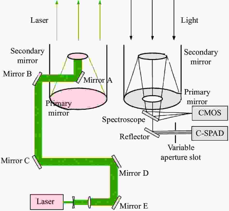
图 2 53 cm双筒望远镜分光路激光测距收/发光路示意图
Figure 2. Optical path schematic for laser ranging transmit/receive in the 53 cm binocular telescope
在测距过程中,激光器发射的激光经一级扩束系统扩束后,依次由反射镜E、D、C、B、A反射至望远镜副镜,通过副镜反射至主镜完成二级扩束后,经大气传输抵达望远镜指向的空间目标位置。经由空间目标反射和大气传输,少部分光子抵达接收主副镜,并反射到分光镜(Spectroscope)和反射镜(Reflector),通过缩束系统后到达单光子探测器C-SPAD进行探测[16]。
-
在53 cm双筒望远镜激光测距系统的反射镜E之后增加一个高灵敏度的激光功率计Ⅰ,功率实时监测光路如图3所示。由于高灵敏度探测器探测口径较小,当激光器发射功率增大时,透射光光斑大于探测器探测口径,导致透射光功率测量值偏小,故采用焦距f=50.8 mm、直径$ \phi = $ 25.4 mm的聚焦透镜将透射光聚焦到激光功率计探头,以保证测量的准确性。将激光功率计探头连接到激光功率计表头后,再由表头连接到PC端,实时传输激光功率及对应时间等数据,并在PC端进行数据的显示、存储和处理。

图 3 实时监测激光功率
Figure 3. Real-time laser power monitoring
为了验证激光功率实时监测光路的激光功率与激光器测距功率之间的线性关系,在激光经过反射镜E反射后的光路中增加一个激光功率计探头Ⅱ用以测量反射光。将两个激光功率计探头分别连接到两个激光功率计表头后,将两个表头连接到同一个PC端进行数据的传输、显示、存储和处理,同时对两路激光的功率进行实时监测,获得透射光实时功率与反射光实时功率,光路图如图4所示。

图 4 反射/透射激光功率线性度测量
Figure 4. Reflected/transmitted laser power linearity measurement
-
目前,53 cm双筒望远镜测距系统所采用的脉冲式激光器最大功率为800 mW,激光功率通过控制激光器电流进行调节。激光器参数如表1所示[17]。
表 1 激光器参数
Table 1. Parameters of the lasers
Parameter Value Wavelength/nm 532 Repeat frequency/Hz 1000 Pulse width/ps 25 Pulse energy/mJ·pulse–1 0.9 (Before)/
0.8 (Present)Beam diameter/mm 3 Laser divergence angle/(″) 5 反射镜E表面所镀的介质膜反射率通常为99.9%,即约有0.1%的激光会在反射镜E处透射。测距链路中激光出射功率、反射光功率与透射光功率范围如表2所示。
由表2可知,由于透射光功率较小,故选用测量范围较小,但测量灵敏度高、响应速度快、受温度影响较小的光电式激光功率探头。反射光功率测量选用功率测量范围宽、相对不容易达到饱和、受光照角度和位置影响较小的热电堆式激光功率计探头[10],激光功率探头Ⅰ、Ⅱ的具体参数如表3所示。
表 2 激光测距链路中各处功率范围
Table 2. Power range at each point in the laser ranging
Output laser
power/mWReflected laser power/mW Transmitted laser power/mW 800 799.2 0.8 400 399.6 0.4 200 199.8 0.2 100 99.9 0.1 35 34.965 0.035 表 3 激光功率计探头参数表
Table 3. Parameters of laser power meter probe
Parameter Value Probe marking Probe Ⅰ Probe Ⅱ Sensor model Thorlabs-S120C Ophir-10A v1.1 Wavelength range 400-1100 nm 190-2 000 nm Power range 50 nW-50 mW 10 mW-10 W Aperture size ϕ9.5 mm ϕ16 mm Measurement uncertainty ±3% (440-980 nm) - Power accuracy - ±3% Resolution 1 nW - Power noise level - 0.2 mW -
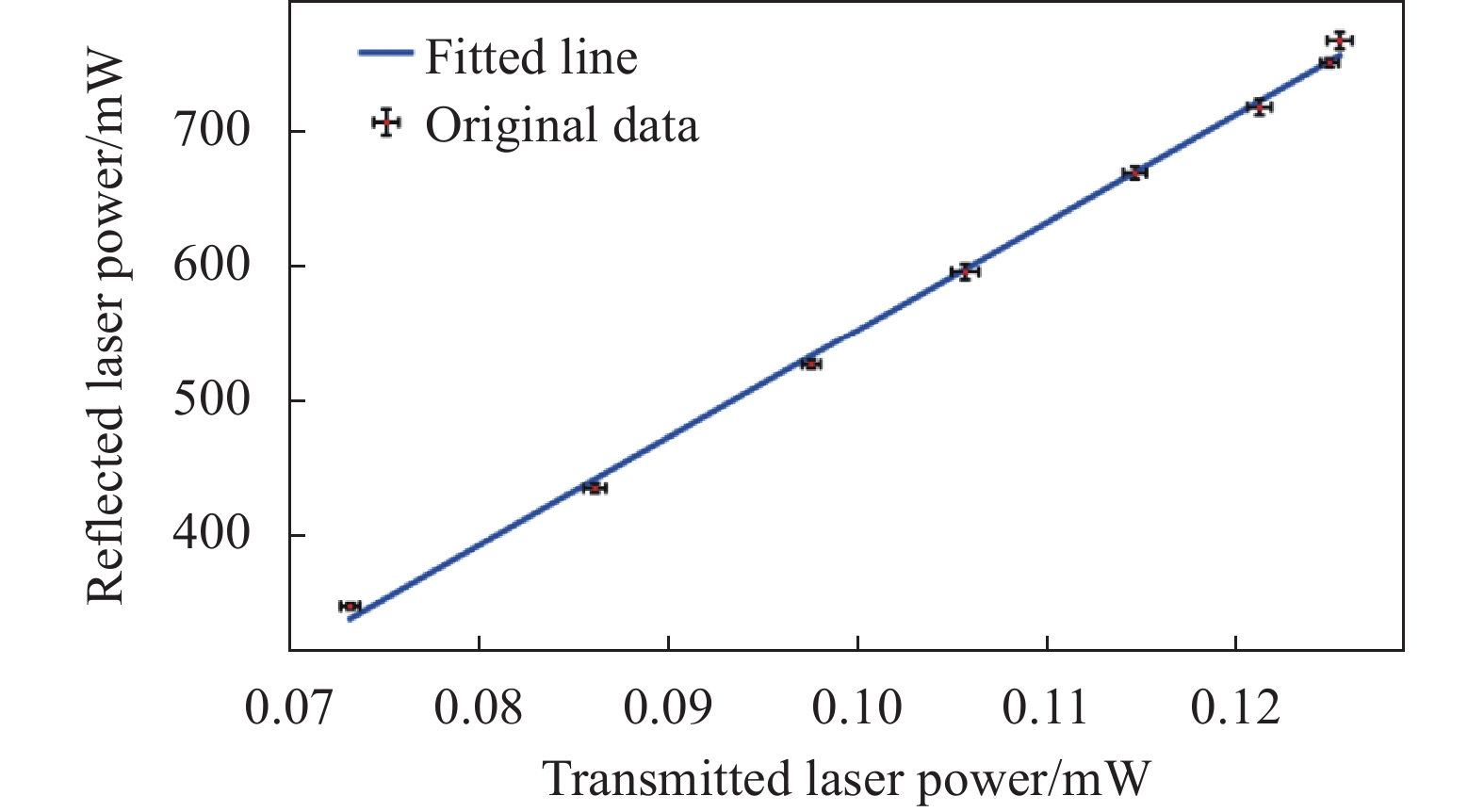
调节激光器电流改变激光功率,以0.5 A为步长,测量了电流在42~44.8 A (激光器最大电流44.8 A)变化时多组激光器的透射激光功率和反射激光功率数据,每组测量2 min,采样频率1 Hz,利用3$ \sigma $准则(Pauta Criterion)进行粗大误差剔除后取算术平均值作为标准点。
由于反射光功率与透射光功率都具有测量误差,其 Spearman相关系数$\; {\rho }_{xy} $为:
$$ {\rho }_{xy}=\frac{{ \displaystyle \sum }_{i=0}^{n}\left({x}_{i}-\overline{x}\right)\left({y}_{i}-\overline{y}\right)}{\sqrt{{ \displaystyle \sum }_{i=0}^{n}{\left({x}_{i}-\overline{x}\right)}^{2}}\sqrt{{ \displaystyle \sum }_{i=0}^{n}{\left({y}_{i}-\overline{y}\right)}^{2}}}=0.999 \; 1$$ (1) 式中:$ {x}_{i} $为透射光功率;$ \overline{x} $为其均值;$ {y}_{i} $为反射光功率;$ \overline{y} $为其均值。
两变量分别拟合得到的回归直线高度重合,利用透射光功率测量值对反射光功率进行最小二乘法直线拟合,误差棒取值为一个标准差,拟合结果如图5所示。

图 5 反射光与透射光功率关系曲线
Figure 5. Relationship curve of reflected light power and transmitted light power
为了验证透射光功率和反射光功率的线性关系,利用F检验法检验回归方程的显著性,对一元线性回归而言[18]:
$$ F=\dfrac{{U}/{{\nu }_{u}}}{{Q}/{{\nu }_{Q}}},\left({\nu }_{u}=1,{\nu }_{Q}=N-2\right) $$ (2) 式中:N为测量值个数;回归平方和$ U={ \displaystyle \sum }_{i=0}^{n}{(\widehat{{y}_{i}}-\overline{y})}^{2} $;残余平方和$ Q={ \displaystyle \sum }_{i=0}^{n}{({y}_{i}-\widehat{{y}_{i}})}^{2} $,y为待拟合数值,其均值为$ \overline{y} $,拟合值为$ \widehat{y} $。
此时,F= 3171.0395,当显著性水平a= 0.10时,F分布表的部分表如表4所示,当$ F \geqslant {F}_{a}({v}_{U},{v}_{Q}) $时,认为回归是高度显著的,线性关系非常密切。
表 4 F分布表部分表P (F≥Fa)的Fa值,${\boldsymbol{ \alpha =0.10}}$
Table 4. Part of F-distribution table Fa value of P (F≥Fa), ${\boldsymbol{ \alpha =0.10}}$
$ {v}_{Q} $ $ {v}_{U} $ 1 2 … 24 $ \infty $ 1 39.86 49.50 … 55.83 63.33 2 8.53 9.00 … 9.45 9.49 … … … … … … 6 3.78 3.46 … 2.82 2.72 … … … … … … 28 2.89 2.50 … 1.66 1.48 … … … … … … 可知$ F > {F}_{a}\left(\mathrm{1,6}\right) $,认为回归高度显著,证明透射光功率和反射光功率具有很好的线性关系。反射激光功率测量值与拟合结果之间的最大偏差值占当前测量值的1.49%,利用残余标准差$ \sigma $来衡量回归直线的精度,当$ \sigma $越小时回归直线精度越高:
$$ \sigma =\sqrt{Q/\left(N-2\right)} $$ (3) 此时,$ \sigma =0.007\;3 $,满足精度需求。由此可知,通过测量透射光功率就能够推出反射光功率。反射光功率$ {y}_{i} $与透射光功率$ {x}_{i} $的关系式为:
$$ {y}_{i}=k{x}_{i}+b $$ (4) 式中: b为常数项;k为比例系数。
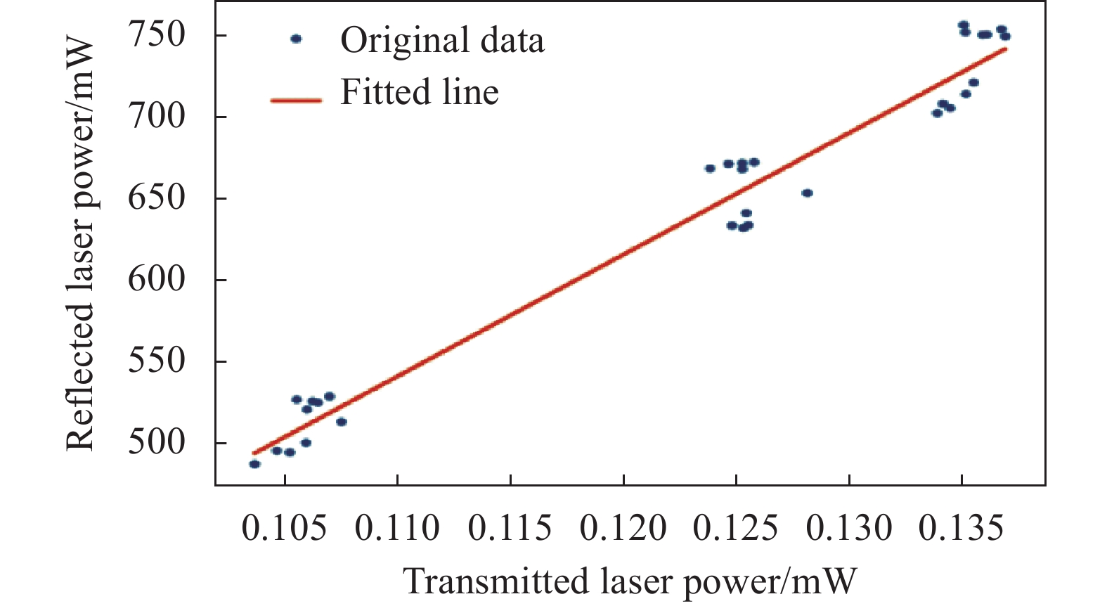
为了验证该方法在长时间卫星激光测距观测中的可靠性,进行时长7 h的测量实验。调节激光器电流改变激光功率,每组测量2 min,采样频率1 Hz,以1 A为步长,电流从42~44 A变化为一大组,测量激光器的透射激光功率和反射激光功率数据,每大组测量共计耗时10 min,共测量10个大组。利用3$ \sigma $准则进行粗大误差剔除后取算术平均值作为标准点,对实验数据进行最小二乘法直线拟合,结果如图6所示。

图 6 激光功率可靠性测量
Figure 6. Laser power reliability measurement
F=1057.7779,可知$ F > {F}_{a}\left(\mathrm{1,28}\right) $,认为回归高度显著。反射激光功率最大偏差值占当前值的3.75%,残余标准差$ \sigma = $0.016 5,精度较高。证明通过该方法计算得到的反射光功率数据具有很好的可靠性。
实验采用的反射镜其表面为介质膜,其单层膜的反射率为:
$$R=\dfrac{{\left({\eta }_{0}-{\eta }_{2}\right)}^{2}{{\rm{cos}}}^{2}{\delta }_{1}+{\left(({{\eta }_{0}{\eta }_{2}})/{{\eta }_{1}}-{\eta }_{1}\right)}^{2}{{\rm{sin}}}^{2}{\delta }_{1}}{{\left({\eta }_{0}+{\eta }_{2}\right)}^{2}{{\rm{cos}}}^{2}{\delta }_{1}+{\left(({{\eta }_{0}{\eta }_{2}})/{{\eta }_{1}}+{\eta }_{1}\right)}^{2}{{\rm{sin}}}^{2}{\delta }_{1}} $$ (E5) 式中:$ {\delta }_{1}=\dfrac{2\pi }{\lambda }{n}_{1}{d}_{1}{\rm{cos}}{\theta }_{1} $,$ {n}_{1} $为膜层折射率,$ {d}_{1} $为膜层厚度,$ {\theta }_{1} $为入射角;$ {\eta }_{0} $为空气的折射率;$ {\eta }_{1} $为有效光学导纳;$ {\eta }_{2} $为基底的折射率[19] 。
由公式(5)可知,对该实验而言,反射镜的反射率仅与激光波长相关,激光功率的变化并不影响反射镜的反射率。同时,在用该方法对激光发射功率做相对测量时,会事先对反射光功率与透射光功率进行标定,保证测量的准确性。因此,对空间碎片激光测距和月球激光测距等需要较大功率测距的系统而言,该方法同样适用。
-
文中所设计的激光功率实时监测方法不仅能够很好地避免对原激光测距光路的影响,而且所测得的透射光功率与激光发射功率具有良好的线性关系,能够满足长时间卫星激光测距的可靠性需求和激光测距过程中功率测量的精度需求。实验结果证明了文中所使用的监测方法可以适用于卫星激光测距过程中的激光功率实时监测,并可推广至各类空间目标激光测距中。
Design and implementation of real-time laser power monitoring system in laser ranging
-
摘要: 在激光测距过程中,实时获取激光发射功率数据可为后续数据精度处理分析及激光测距系统故障点排查提供重要依据。通过实时测量激光发射链路中的反射镜透射光,利用前期获取的反射镜透射光与反射镜反射光之间的对应关系,采取相对测量的方式获取实时的反射光功率,达到实时监测激光发射功率的效果,并基于中国科学院云南天文台53 cm双筒望远镜激光测距系统搭建实验平台进行验证。实验结果表明,该激光功率实时监测方法能够在激光发射链路无损耗的前提下实时获取激光发射功率;反射光功率与透射光功率具有良好的线性关系,其Spearman相关系数为0.9991,线性关系稳定可靠,满足长时间激光测距的需求;验证了该方法的可行性,可适用于各类空间目标激光测距的激光功率实时监测中。Abstract:
Objective In laser ranging processes, Single-Photon Avalanche Diode (SPAD) is commonly used as a detector. However, this type of detector exhibits a time-walk effect, where different input energies result in different photon detection times. In such cases, it is necessary to monitor the laser power in real-time to analyze the variations in laser energy and the impact of the detector itself on ranging accuracy. Furthermore, due to the complexity of satellite laser ranging systems, troubleshooting typically requires a significant amount of time. Real-time monitoring of laser power allows for quick identification and troubleshooting of laser transmitter energy, reducing the time required for identifying system faults. Therefore, obtaining real-time laser emission power data serves as a crucial basis for subsequent analysis of data accuracy and troubleshooting of laser ranging system faults. Methods To address the limitations of traditional real-time laser power monitoring techniques, such as laser energy attenuation, susceptibility to introducing optical axis deviation, and difficulties in practical application, a real-time laser power monitoring method is proposed for laser ranging systems. Here is the method: Before ranging, insert laser power meter II into the optical path and adjust the laser diode current to obtain multiple sets of different laser emission powers. Use laser power meters I and II to measure the transmitted light and reflected light from the reflector respectively, establishing the corresponding relationship between transmitted and reflected light (Fig.4). During ranging, remove laser power meter II from the optical path, and laser power meter I continuously measures the transmitted light from the reflector in the laser emission path (Fig.3). Utilize the previously established corresponding relationship between transmitted and reflected light to obtain real-time reflected light power through relative measurement. This achieves the effect of real-time monitoring of laser emission power. Validate the method by constructing an experimental platform based on the 53 cm dual-tube telescope at Yunnan Observatory. Results and Discussions By adjusting the laser diode current to change the laser power, multiple sets of data for the transmitted laser power and reflected laser power were measured. The data was then used to perform a linear fit using the least squares method. The significance of the regression equation was evaluated using the F-test, yielding an F-value of 3 171.039 5. Consulting the F-distribution table revealed that the regression was highly significant, indicating a strong linear relationship between the reflected and transmitted laser powers. The residual standard deviation (σ) of the regression equation was found to be 0.007 3. The maximum deviation between the measured values of reflected laser power and the fitted results was 1.49% of the current measurement, demonstrating that the regression line accuracy meets the requirements for laser ranging (Fig.5). The proposed method was subjected to intermittent measurements over a duration of 7 hours. The F-value obtained from the F-test was 1057.7779, which means the regression was still highly significant. The residual standard deviation (σ) was calculated to be 0.0165, and the maximum deviation value of the reflected laser power measurement from the fitted result is 3.75% of the current measurement value. This meets the accuracy requirements, demonstrating that the proposed method can maintain long-term stability and fulfill the needs of long-time satellite laser ranging (Fig.6). Conclusions The experimental results indicate that the proposed method of real-time laser power monitoring can accurately obtain the laser emission power without loss in the laser emission path. The reflected laser power and transmitted laser power exhibit a strong linear relationship, with a Spearman correlation coefficient of 0.999 1. This linear relationship remains stable and reliable during long-duration laser ranging experiments. The feasibility of this method has been verified, meeting the power measurement requirements for laser ranging of various spatial targets. Therefore, this method can be applied to the real-time monitoring of laser power for various spatial objects laser ranging. -
图 2 53 cm双筒望远镜分光路激光测距收/发光路示意图
Figure 2. Optical path schematic for laser ranging transmit/receive in the 53 cm binocular telescope
图 5 反射光与透射光功率关系曲线
Figure 5. Relationship curve of reflected light power and transmitted light power
表 1 激光器参数
Table 1. Parameters of the lasers
Parameter Value Wavelength/nm 532 Repeat frequency/Hz 1000 Pulse width/ps 25 Pulse energy/mJ·pulse–1 0.9 (Before)/
0.8 (Present)Beam diameter/mm 3 Laser divergence angle/(″) 5  下载: 导出CSV
表 2 激光测距链路中各处功率范围
Table 2. Power range at each point in the laser ranging
Output laser
power/mWReflected laser power/mW Transmitted laser power/mW 800 799.2 0.8 400 399.6 0.4 200 199.8 0.2 100 99.9 0.1 35 34.965 0.035
下载: 导出CSV
表 3 激光功率计探头参数表
Table 3. Parameters of laser power meter probe
Parameter Value Probe marking Probe Ⅰ Probe Ⅱ Sensor model Thorlabs-S120C Ophir-10A v1.1 Wavelength range 400-1100 nm 190-2 000 nm Power range 50 nW-50 mW 10 mW-10 W Aperture size ϕ9.5 mm ϕ16 mm Measurement uncertainty ±3% (440-980 nm) - Power accuracy - ±3% Resolution 1 nW - Power noise level - 0.2 mW
下载: 导出CSV
表 4 F分布表部分表P (F≥Fa)的Fa值,${\boldsymbol{ \alpha =0.10}}$
Table 4. Part of F-distribution table Fa value of P (F≥Fa), ${\boldsymbol{ \alpha =0.10}}$
$ {v}_{Q} $ $ {v}_{U} $ 1 2 … 24 $ \infty $ 1 39.86 49.50 … 55.83 63.33 2 8.53 9.00 … 9.45 9.49 … … … … … … 6 3.78 3.46 … 2.82 2.72 … … … … … … 28 2.89 2.50 … 1.66 1.48 … … … … … …
下载: 导出CSV
-
[1] 李祝莲, 熊耀恒, 何妙婵等. 云南天文台人造卫星激光测距系统原理[J]. 天文研究与技术, 2008, No. 19(03): 248-252. doi: 10.14005/j.cnki.issn1672-7673.2008.03.009. Li Zhulian, Xiong Yaoheng, He Miaochan, et al. Principle of 1.2 m telescope satellite laser ranging system [J]. Astronomical Research and Technology, 2008, 5(3): 248-252. (in Chinese) doi: 10.14005/j.cnki.issn1672-7673.2008.03.009 [2] 叶叔华, 黄珹. 天文地球动力学 [M]. 济南: 山东科学技术出版社, 2000. [3] 陈瑞强, 江月松, 裴朝. 基于双阈值前沿时刻鉴别法的高频脉冲激光测距系统 [J]. 光学学报, 2013, 33(09): 155-62. doi: 10.3788/AOS201333.0912002. Chen Ruiqiang, Jiang Yuesong, Pei Zhao. High frequency and high accuracy laser ranging system based on double thresholds leading-edge timing discrimination [J]. Acta Optica Sinica, 2013, 33(9): 0912002. (in Chinese) doi: 10.3788/AOS201333.0912002 [4] Kirchner G, Koidl F. Compensation of SPAD time-walk effects [J]. Journal of Optics A: Pure and Applied Optics, 1999, 1(2): 163-167. doi: 10.1088/1464-4258/1/2/008 [5] ILRS. Ground Segment [EB/OL]. [2023-05-29]. https://ilrs.gsfc.nasa.gov/technology/groundSegment/index.html. [6] 李祝莲, 张海涛, 李语强, 等. 53 cm双筒望远镜高重频空间碎片激光测距系统 [J]. 红外与激光工程, 2017, 46(07): 277-81. doi: 10.3788/IRLA201746.0729001. Li Zhulian, Zhang Haitao, Li Yuqiang, et al. 53 cm binocular telescope high repetition frequency space debris laser ranging system [J]. Infrared and Laser Engineering, 2017, 46(7): 0729001. (in Chinese) doi: 10.3788/IRLA201746.0729001 [7] 张海涛, 李祝莲, 汤儒峰, 等. 阵列探测技术在激光测距中的应用[J]. 红外与激光工程, 2020, 49(10): 20200006. doi: 10.3788/IRLA20200006. Zhang Haitao, Li Zhulian, Tang Rufeng, et al. Application of array detection technology in laser ranging [J]. Infrared and Laser Engineering, 2020, 49(10): 20200006. (in Chinese) doi: 10.3788/IRLA20200006 [8] 丁仁杰, 吴志波, 邓华荣, 等. 高自动化卫星激光测距系统研究与设计 [J]. 激光与红外, 2017, 47(09): 1102-7. )doi: 10.3969/j.issn.1001-5078.2017.09.008. Ding Renjie, Wu Zhibo, Deng Huarong, et al. Research and design of high automation satellite laser ranging system [J]. Laser & Infrared, 2017, 47(9): 1102-1107. (in Chinese) doi: 10.3969/j.issn.1001-5078.2017.09.008 [9] 董雪, 韩兴伟, 宋清丽, et al. 空间碎片激光测距系统研究 [J]. 红外与激光工程, 2016, 45(S2): 35-40. doi: 10.3788/IRLA201645.S229002. Dong Xue, Han Xingwei, Song Qingli, et al. Research of space debris laser ranging system [J]. Infrared and Laser Engineering, 2016, 45(S2): S229002. (in Chinese) doi: 10.3788/IRLA201645.S229002 [10] 陈舒凡, 房丰洲. 激光功率计发展及应用 [J]. 激光与光电子学进展, 2021, 58(09): 41-54. doi:10. 3788/LOP202158. 0900003. Chen Shufan, Fang Fengzhou. Development and applications of laser power meter [J]. Laser & Optoelectronics Progress, 2021, 58(9): 0900003. (in Chinese) doi: 10.3788/LOP202158.0900003 [11] 曹俊忠, 鲍振武. 光缆光功率实时监测 [J]. 光通信研究, 2003, 02): 34-7. )doi: 10.13756/j.gtxyj.2003.02.010. Cao Junzhong, Bao Zhenwu. Optical power real-time super-vision for optical cable [J]. Study on Optical Communications, 2003, 2(2): 34-37. (in Chinese) doi: 10.13756/j.gtxyj.2003.02.010 [12] 郁擎红, 杨扬, 李家镕. 大功率CO2激光功率实时监测仪[J]. 仪表技术, 1997(1): 19-21. doi: 10.19432/j.cnki.issn1006-2394.1997.01.007 [13] 彭登峰, 王又青, 李波. 高功率激光实时检测与控制系统的研究 [J]. 激光技术, 2006, 30(5): 483-485. doi: 10.3969/j.issn.1001-3806.2006.05.018 Peng Dengfeng, Wang Youqing, Li Bo. Real-time power measurement and control system of high power CO2 lasers [J]. Laser Technology, 2006, 30(5): 483-485. (in Chinese) doi: 10.3969/j.issn.1001-3806.2006.05.018 [14] 乔健, 高云国, 韩光宇, 等. 水平式两轴转台中库德光路的快速装调 [J]. 光学精密工程, 2010, 18(8): 1760-1765 doi: 10.3788/OPE.20101808.1760. Qiao Jian, Gao Yunguo, Han Guangyu, et al. Fast alignment of Coude optical system in alt-alt two axis tracking turntable [J]. Optics and Precision Engineering, 2010, 18(8): 1760-1765. (in Chinese) doi: 10.3788/OPE.20101808.1760 [15] 薛向尧, 高云国, 张文豹, 等. 库德光路光束指向稳定性分析 [J]. 红外与激光工程, 2013, 42(06): 1514-8. doi: 10.3969/j.issn.1007-2276.2013.06.023 Xue Xiangyao, Gao Yunguo, Zhang Wenbao, et al. Analysis of the beam pointing stability in coude optical path [J]. Infrared and Laser Engineering, 2013, 42(6): 1514-1518. (in Chinese) doi: 10.3969/j.issn.1007-2276.2013.06.023 [16] 翟东升, 李语强, 徐蓉, 等. 云南天文台一发多收激光测距系统设计与实现 [J]. 天文研究与技术, 2017, 14(03): 310-316. doi: 10.14005/j.cnki.issn1672-7673.20161130.002. Zhai Dongsheng, Li Yuqiang, Xu Rong, et al. Design and realization of single telescope transmitting and twin receiving laser ranging system at Yunnan observatories [J]. Astronomical Research and Technology, 2017, 14(3): 310-316. (in Chinese) doi: 10.14005/j.cnki.issn1672-7673.20161130.002 [17] 李春晓, 李祝莲, 汤儒峰, 等. 一发两收卫星激光测距系统中目标距离测量试验 [J]. 红外与激光工程, 2020, 49(S1): 19-25. doi: 10.3788/IRLA20200145. Li Chunxiao, Li Zhulian, Tang Rufeng, et al. Target distance measurement experiment with a bi-static satellite laser ranging system [J]. Infrared and Laser Engineering, 2020, 49(S1): 20200145. (in Chinese) doi: 10.3788/IRLA20200145 [18] 费业泰. 误差理论与数据处理 [M]. 北京: 机械工业出版社, 2015. [19] 卢进军, 刘卫国. 光学薄膜技术[M]. 北京: 电子工业出版社, 2011. -

 点击查看大图

计量
- 文章访问数: 103
- HTML全文浏览量: 27
- PDF下载量: 57
- 被引次数: 0

