


-
近年来,随着空间遥感探测、AR、VR等应用光学领域的蓬勃发展,光学成像系统往往被要求工作于大口径、大视场等复杂环境中,因而有效补偿系统像差成为保障其成像质量的关键。自由曲面具有远多于球面和非球面的设计自由度,由此具备着远胜于球面和非球面的像差补偿和光束整形能力,其在各类非成像以及成像系统中均得到广泛应用[1-8]。
然而,值得考虑的是,虽然自由曲面的多设计自由度为像差补偿带来更多可能,但它却也大大增加了优化设计的难度。为了得到合理的设计结果,常常需要采用一些特殊的优化设计方法。常用的自由曲面初始结构设计以及后续优化方法包括:微分方程法[9]、多曲面同步设计法[10]、像差理论指导设计法[11]、机器学习设计法[12]、逐步逼近优化法[13]等。其中,对于补偿系统像差的自由曲面设计来说,采用基于像差理论的优化设计方法可以较为直接地满足于设计需求,提高优化设计的效率。
以像差理论为指导的优化设计方法分为:标量像差理论优化和矢量像差理论优化两种方法。其中,标量像差理论优化法依赖于经典几何像差和波像差理论,其主要适用对象为旋转对称系统,该方法也是众多商用光学设计软件的主要优化方法。但对于存在自由曲面的非旋转对称系统,因自由曲面的非旋转对称性,以及难以明确面形与像差之间的映射关系,致使经典的像差理论容易产生系统像差的表征误差,会对自动优化的速度和结果的精度产生不利影响。与之不同的是,矢量像差理论则可准确给出Zernike型自由曲面面形与系统波像差之间的对应关系[14-17]。从理论上来说,采用矢量像差理论的优化设计方法,依据系统的波像差特性,通过对引入自由曲面的面形求解,可以实现对系统波前像差的精准补偿和调控,以此能显著增强成像系统的像质,提升系统整体性能。
文中以矢量像差理论为核心,介绍了一种针对成像系统像差补偿自由曲面的优化设计方法。为了验证该方法优化设计出的自由曲面对于成像系统像差补偿效果,搭建了存在明显像差的望远偏心系统作为系统实例,分别采用两种方法优化设计像差补偿自由曲面,并从仿真和实验上进行像差补偿效果、像质提升的对比研究。结果表明,基于矢量像差理论优化设计出的自由曲面,对于系统像差补偿以及像质提升方面具有更好的效果,其在成像系统像差补偿自由曲面优化设计、提升系统像质以及通过自由曲面调控系统波像差等方面具有一定的应用研究价值和指导意义。
-
矢量像差理论是在标量像差理论的基础上,将归一化光瞳与视场矢量化后得出的。当Zernike型自由曲面位于光学系统不同位置时,其对于同一视场、同一光瞳位置的光束波前调制不同,导致其最终对于系统波像差的贡献量不同,故而需要分不同情况讨论。
-
当自由曲面位于光阑处时,不同视场的光束入射至自由曲面时轨迹一致,因而自由曲面对其光程的改变量与视场无关,只与光束照射在自由曲面上的位置有关,其对系统波像差的贡献量可写作:
$$ W\left(\overrightarrow{\rho }\right)=\frac{\left(n{'}-n\right)}{\lambda }\overrightarrow{C} \cdot Z\left(\overrightarrow{\rho }\right) $$ (1) 式中:$ W(\overrightarrow \rho ) $为自由曲面对系统波像差的贡献量;$ \lambda $为光波波长;$ \overrightarrow C $为每项Zernike项对应的系数矢量;$ n $和$ n' $分别为入射光与反射光或折射光所在空间的折射率。值得说明的是,在反射式系统中,对于奇数次和偶数次反射,公式(1)具有不同的表示形式[16]:
$$ W\left(\overrightarrow{\rho }\right)=\left\{\begin{array}{c}-\dfrac{2\overrightarrow{C}\cdot Z\left(\overrightarrow{\rho }\right)}{\lambda },\;odd,\;n=1,\;n{'}=-1\\ \dfrac{2\overrightarrow{C}\cdot Z\left(\overrightarrow{\rho }\right)}{\lambda },\;even,\;n=-1,\;n{'}=1\end{array}\right. $$ (2) 当系统视场较小,像差在全视场变化不大时,可考虑将自由曲面置于光阑处进行像差补偿。
-
当自由曲面位于共轴系统非光阑处时,不同视场的光束会照射至自由曲面不同位置处,而同一视场光束只会覆盖自由曲面某一部分区域。具体情况如图1所示,某视场光束在自由曲面上的轨迹会缩小且相对自由曲面几何中心有一定的偏离,此时自由曲面对该光束光程影响将由视场和光瞳共同决定。

图 1 自由曲面位于非光阑处光瞳矢量$ \overrightarrow \rho ' $示意图
Figure 1. Schematic diagram of the pupil vector $ \overrightarrow \rho ' $ when a freeform surface located at a non-aperture location
依据图1所示光瞳矢量变化规律以及矢量叠加原理,此时归一化光瞳矢量的表达式为:
$$ \overrightarrow \rho ' = \alpha \overrightarrow \rho + \beta \overrightarrow H $$ (3) 式中:$ \overrightarrow \rho ' $为非光阑处缩小且离心后光束轨迹对应的归一化光瞳矢量;$ \alpha $和$\; \beta $分别表示光瞳缩放因子和光束孔径离心因子。$ \alpha $和$\; \beta $的计算表达式为:
$$ \alpha = \frac{y}{D},\;\beta = \frac{{\overline y }}{D} $$ (4) 式中:$ y $表示边缘光线在自由曲面上的入射高度;$ \overline y $表示边缘视场主光线在自由曲面上的投射高度;D为自由曲面的半口径;$ y $和$ \overline y $均可通过光线追迹的方式得到。
将公式(3)代入公式(1)中,可得在非光阑处,自由曲面对系统波像差的贡献量表达式:
$$ W\left(\overrightarrow{\rho }\right)=\dfrac{\left(n{'}-n\right)}{\lambda }\overrightarrow{C}\cdot Z\left(\alpha \overrightarrow{\rho }+\beta \overrightarrow{H}\right) $$ (5) 对于$ n $和$ n' $的取值情况与上述位于光阑处一致[16]。对于视场较大,像差随视场变化较明显的系统,可选择非光阑位置的自由曲面进行像差补偿。依据公式(1)和公式(5)即可求得Zernike型自由曲面各项引起的波像差类型以及相关系数;相反,当通过向系统中引入自由曲面来补偿波像差时,可依据上述两公式反解出补偿系统波像差所需要的自由曲面项和系数,这就是依据矢量像差理论进行自由曲面优化设计的核心思想。表1则给出了补偿几种典型初级波像差所需的Fringe Zernike自由曲面项以及相关系数。
表 1 初级像散、离焦以及初级彗差项对应的Fringe Zernike项及系数
Table 1. Fringe Zernike terms and coefficients corresponding to primary astigmatism, defocusing, and primary coma terms
Wave aberration terms Corresponding Zernike terms and coefficients Primary astigmatism $ \begin{gathered} {\overrightarrow Z _{5/6}},{\alpha ^2}{\overrightarrow C _{5/6}} \\ {\overrightarrow Z _{7/8}},3{\alpha ^2}\left( {{{\overrightarrow C }_{7/8}}\overrightarrow H } \right) \\ {Z_9},12{\alpha ^2}{\beta ^2}\left( {{C_9}{{\overrightarrow H }^2}} \right) \\ {\overrightarrow Z _{10/11}},3{\alpha ^3}\beta \left( {{{\overrightarrow C }_{10/11}}{{\overrightarrow H }^ * }} \right) \\ {\overrightarrow Z _{12/13}},\left[ {12{\alpha ^2}{\beta ^2}\left( {{{\left| {\overrightarrow H } \right|}^2}{{\overrightarrow C }_{12/13}}} \right) - 3{\alpha ^2}{{\overrightarrow C }_{12/13}}} \right] \\ \end{gathered} $ Defocus $\begin{array}{l}{Z}_{4},{\alpha }^{2}{C}_{4}\\ {\overrightarrow{Z} }_{7/8},3{\alpha }^{2}\beta \left({\overrightarrow{C} }_{7/8}\cdot \overrightarrow{H}\right)\\ {Z}_{9},12{\alpha }^{2}{\beta }^{2}{C}_{9}(\overrightarrow{H}\cdot \overrightarrow{H})\\ {\overrightarrow{Z} }_{12/13},6{\alpha }^{2}{\beta }^{2}\left({\overrightarrow{C} }_{12/13}\cdot {\overrightarrow{H} }^{2}\right)\end{array}$ Primary coma $ \begin{gathered} {\overrightarrow Z _{7/8}},{\alpha ^2}{\overrightarrow C _{7/8}} \\ {Z_9},8{\alpha ^3}\beta \left( {{C_9}\overrightarrow H } \right) \\ {\overrightarrow Z _{12/13}}{\text{,4}}{\alpha ^3}\beta \left( {{{\overrightarrow C }_{12/13}}{{\overrightarrow H }^ * }} \right) \\ \end{gathered} $ -
利用上述Zernike型自由曲面面形与波像差之间的对应关系,结合相应的面形参数迭代求解算法,即可利用矢量像差理论完成自由曲面优化设计。迭代求解算法的核心逻辑是通过一次次循环迭代求解自由曲面各项系数,让光学系统像差特性逐渐逼近优化目标像差,当迭代结果与目标之间差值小于误差阈值时,即可退出迭代,得到优化设计的自由曲面面形结果。依据波像差叠加特性,优化后的目标波像差可由初始波像差以及自由曲面引入的波像差叠加而得到:
$$ W = {W_0} + {W_{\text{F}}} $$ (6) 式中:$ W $为优化后的波像差;$ {W_0} $为系统初始波像差;$ {W_{\text{F}}} $则为自由曲面引入后对系统波像差的贡献量。
基于上述的算法逻辑,结合Zernike型自由曲面各项对系统波像差贡献量的规律,以系统波像差为主导的优化迭代算法流程如下:
(a)利用光学设计软件获取初始光学系统的波像差特性,同步输入各波像差系数,记为实际波像差$ {W_{{\text{act}}}} $;将优化迭代后期望得到的波像差特性记为目标波像差$ {W_{{\text{tar}}}} $,对于以补偿系统像差为设计目标,一般使得$ {W_{{\text{tar}}}} = 0 $。
(b)开始迭代计算,初始迭代次数$ i{\text{ = 1}} $,初始系统实际像差$ {W_{{\text{act}}}}(i - 1) = {W_{{\text{act}}}} $。
(c)定义迭代计算误差上限$ \varepsilon $。
(d)根据类似于表1中每一种波像差对应的Zernike项类型及系数,求解出产生目标像差$ {W_{{\text{tar}}}} $所需的自由曲面面形量$ Z(i) $。
(e)将$ Z(i) $同步添加到自由曲面上,并使用软件获得当前光学系统的像差分布$ {W_{{\text{act}}}}(i) $。
(f)计算由波像差的计算误差和拟合误差造成的$ {W_{{\text{act}}}}(i) $和$ {W_{{\text{tar}}}} $的差值$ \Delta W\left( i \right) $。
(g)如果$ \Delta W\left( i \right) $大于预期的迭代误差$ \varepsilon $,需要进行下一次迭代来补偿$ \Delta W\left( i \right) $。在第$ i + 1 $次迭代时,将$ \Delta W\left( i \right) $作为新的光学系统实际像差引入$ {W_{{\text{act}}}}(i + 1) $。
(h)重复迭代,直到$ \Delta W\left( i \right) $小于迭代误差阈值$ \varepsilon $,然后输出此时自由曲面面形以及光学系统实际波像差$ {W_{{\text{act}}}} $。
其流程图如图2所示。
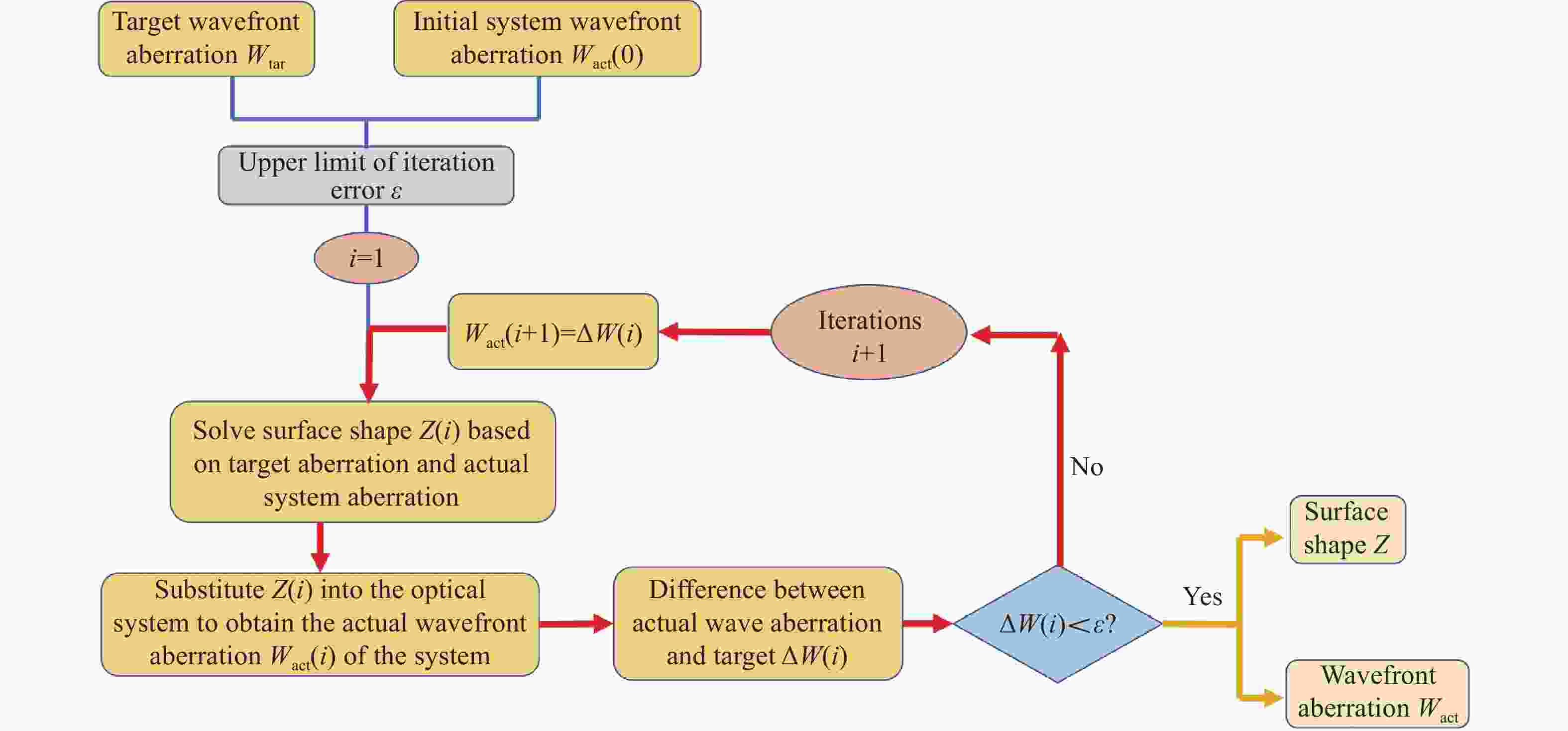
图 2 基于矢量像差理论的自由曲面优化迭代算法流程图
Figure 2. Flowchart of iterative algorithm for freeform surface optimization based on nodal aberration theory
按照上述流程编写出优化算法,结合光学设计软件分析成像系统的初始像差特性,依据其特性选取补偿系统像差的对应自由曲面项,最终由优化迭代算法求解出相应的系数。这便是以矢量像差理论为指导,优化设计像差补偿自由曲面,以此来提升系统像质的整体过程。
-
为了验证上述基于矢量像差理论优化设计方法的有效性,及其在成像系统像差补偿自由曲面优化设计中应用的效果,搭建了望远系统,通过镜组偏心产生明显像差,将该偏心系统作为设计实例,利用自由曲面进行像差补偿。
-
首先,采用两片共焦的凸透镜来搭建简易的望远系统;其次,通过精确位移台控制其中一片透镜产生横向2 mm偏心,以此来产生因光学元件离轴带来的像差,在望远系统后设置聚焦透镜和CCD会聚光束并记录光斑,通过对平行光束经过望远系统后再会聚的光斑形状和大小来反映系统的像差情况;然后,在望远镜前设置自由曲面反射镜来补偿系统像差,为方便实验验证,将使用反射式空间光调制器(SLM)加载自由曲面对应的相位调制图,实现与自由曲面相同的波前调制和像差补偿效果。
用以组成望远系统以及后续聚焦的透镜采用大恒GCL-010111K9平凸透镜,依据透镜以及SLM(中科微星FSLM-2K70-VIS)相关参数,在光学设计软件中搭建望远偏心系统的仿真光路,其仿真示意图如图3所示。表2给出了该系统仿真的详细参数表,其中系统的入瞳直径设置为8 mm以便适配SLM的靶面尺寸,而波长则为SLM的中心波长632.8 nm。

图 3 自由曲面望远偏心系统仿真示意图
Figure 3. Simulation diagram of freeform surface telescopic eccentric system
表 2 自由曲面补偿望远偏心系统像差仿真参数表
Table 2. Simulation parameter table of freeform surface compensating telescopic eccentric system’s aberration
Surface Type Radius/mm Thickness/mm Glass Refraction/Reflex Semi-diameter/mm Decenter/Tilt Object Sphere Inf Inf - Refraction - - Stop Sphere Inf 470.00 - Refraction 4.00 - 2 Zernike Inf −283.00 - Reflex 4.10 Tilt 4.6° 3 Sphere −51.68 −5.00 K9 Refraction 12.70 Decenter 2 mm 4 Sphere Inf −197.50 - Refraction 12.70 - 5 Sphere −51.68 −5.00 K9 Refraction 12.70 - 6 Sphere Inf −71.00 - Refraction 12.70 - 7 Sphere −51.68 −5.00 K9 Refraction 12.70 - 8 Sphere Inf −96.23 - Refraction 12.70 - Image Sphere Inf 0.00 - Refraction 1.00 - -
在光学设计软件中搭建完上述仿真系统后,利用其分析该系统的波像差特性,如图4所示为采用Z4~Z15项Standard Zernike多项式拟合的偏心2 mm望远系统波像差分布图。从图中可以看出,初始系统主要波像差为离轴带来的初级像散、离焦以及初级彗差等。而表1也给出这三种像差对应的Fringe Zernike项以及系数,故在后续利用矢量像差理论优化法优化时,通过迭代算法求解这几项的系数即可得到像差补偿自由曲面的面形;而在利用标量像差理论优化法时,可同样优化这几项来补偿像差。

图 4 望远偏心系统波像差分布图 ($ {{\lambda = 632}}{\text{.8 nm}} $)
Figure 4. Wave aberration distribution map of the telescopic eccentric system ($ {{\lambda = 632}}{\text{.8 nm}} $)
-
在完成上述望远偏心系统搭建并确定其像差特性后,可利用文中1.2节的矢量像差理论优化设计算法对其像差补偿自由曲面进行优化设计,并从仿真以及实验角度对优化设计后的像差补偿、像质提升效果进行分析。由于自由曲面位于系统非光阑处,依据光线追迹求得光瞳缩放因子$ \alpha = 0.975\;6 $,由于光路中为0视场入射至自由曲面处,故表1中与视场有关的Fringe Zernike自由曲面项都为0。优化时设置迭代次数为20次,目标波像差为$ {W_{{\text{tar}}}} = 0 $,而迭代的误差上限设置为$ {{\varepsilon = 0}}{{.001\lambda }} $。作为对比,采用商用光学设计软件中的传统标量像差理论优化法,设置引入的Fringe Zernike自由曲面的Z4~Z8项为优化变量,利用软件自带优化模块进行优化设计。
-
对于优化设计后自由曲面在仿真上的像差补偿效果分析,将分别从优化前后系统波像差、像面处光斑以及系统MTF曲线三个方面进行比较。
-
表3给出了优化设计后的自由曲面面形各项面形系数。其中SAT(Scalar Aberration Theory, SAT)表示标量像差理论优化法,NAT(Nodal Aberration Theory)表示矢量像差优化法。
表 3 两种方法优化设计出补偿望远偏心系统像差自由曲面各项系数
Table 3. Optimized various coefficients of freeform surfaces to compensate the telescopic eccentric system’s aberration by two methods
Standard Zernike terms Z4 Z5 Z6 Z7 Z8 SAT 1.1150e-4 8.5520e-5 0 0 −1.4553e-4 NAT 9.9357e-5 1.1608e-4 0 0 −1.5360e-4 图5则给出了采用Z4~Z9项Standard Zernike多项式拟合的优化前后的系统波像差,图中黄色柱状图表示优化之前系统的波像差分布,绿色柱状图则为SAT优化后系统残留波像差,而紫色柱状图代表NAT优化后的结果,对比可以看出较于优化之前,两种方法均能有效补偿系统像差。而仔细观察发现,使用NAT优化后的系统残留波像差,较于SAT优化后的结果明显更小,尤其是初级像散、离焦以及初级彗差这几项主要影响像质的像差,实现补偿后接近于0的效果。

图 5 优化前及两种方法优化后望远偏心系统波像差分布图($ \lambda = $$ 632{\text{.8 nm}} $)
Figure 5. Wave aberration distribution map of the eccentric telescope system before and after optimization by two methods ($ {{\lambda = 632}}{\text{.8 nm}} $)
-
图6给出了优化前后像面处光斑的图样,从图中明显观察到两种方法优化后光斑的形状规则度大幅提升,光斑尺寸也显著减小。虽然对比图(b)和(c),没有发现两种方法优化后光斑在形状规则度上有明显区别,但通过计算光斑RMS半径可以发现,经过NAT优化后,光斑RMS半径由优化前的0.052 mm,减小至0.017 mm;而经过SAT优化后,光斑RMS半径为0.018 mm,略大于NAT优化后的光斑半径,这也与图5中SAT优化后系统残留波像差相对较大的结果一致。

图 6 优化前以及两种方法优化后望远偏心系统仿真光斑图。(a)优化前;(b) NAT优化后;(c) SAT优化后
Figure 6. Light spot patterns of the eccentric telescope system before and after optimization by two methods. (a) Before optimization; (b) After NAT optimization; (c) After SAT optimization
-
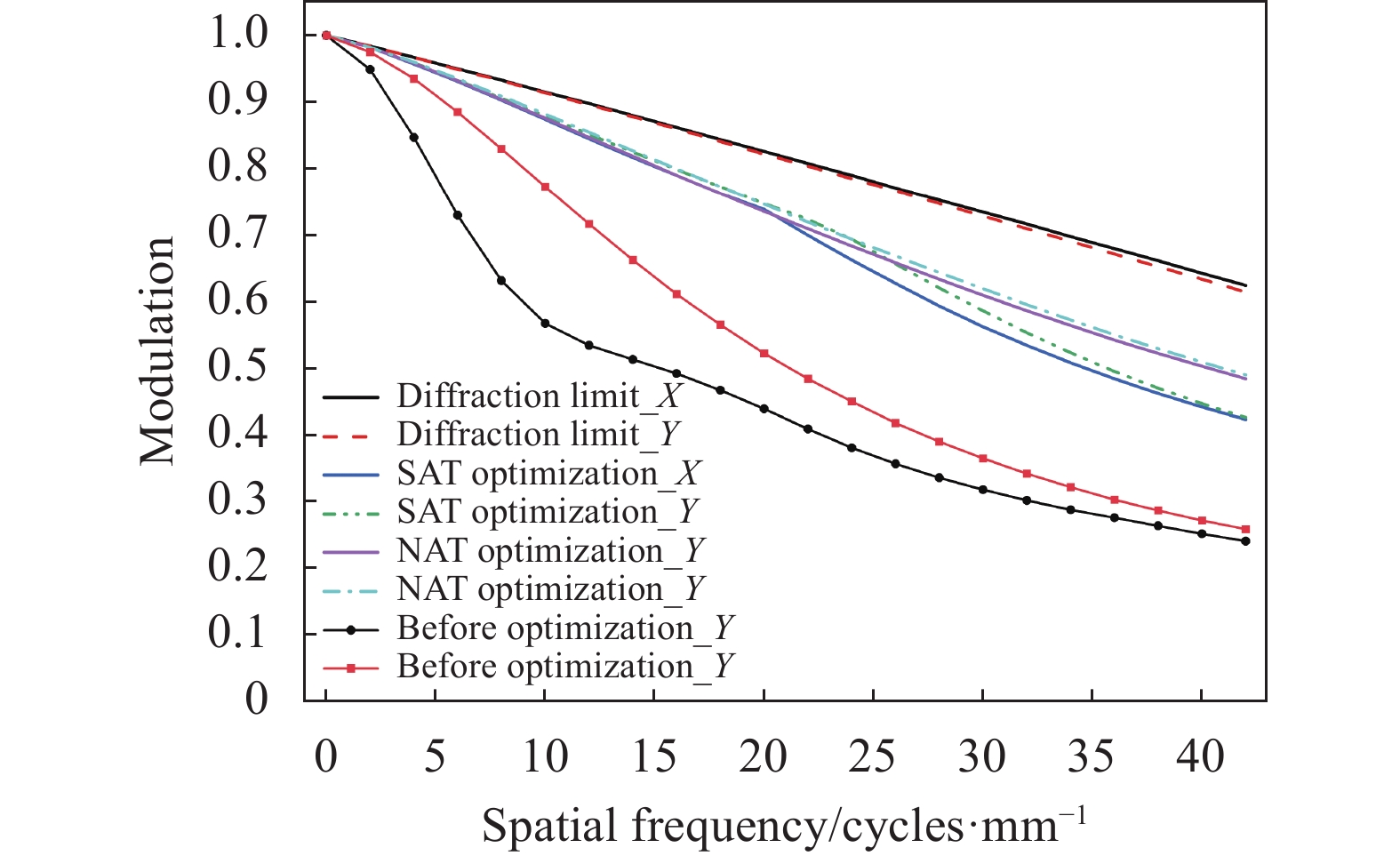
MTF曲线常被用于衡量光学系统的成像质量,图7则给出了优化前后的系统MTF曲线。从图中可以发现,较于优化前的黑色圆形点线和红色方形点线图,两种方法优化后的MTF曲线均明显改善,但随着空间频率的增加,基于矢量像差理论优化的结果(紫色实线以及青色点划线),要略优于标量像差理论优化的结果(蓝色实线和绿色点划线)。
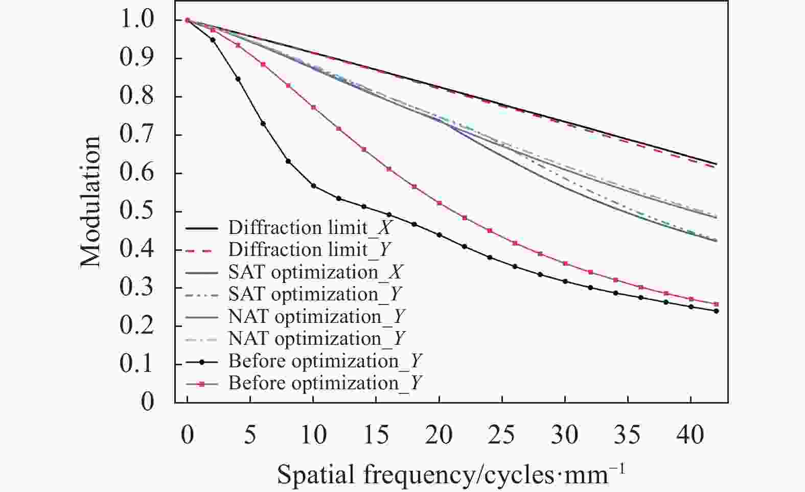
图 7 优化前及两种方法优化后系统像面处MTF曲线
Figure 7. MTF curve at the image plane of the system before and after optimizing by two methods
从上述仿真对比结果发现,采用基于矢量像差理论优化设计方法所得到的自由曲面,能够有效补偿望远偏心系统的像差,而且相较于标量像差理论优化法,具有更好的像差补偿以及系统像质提升的效果。
-
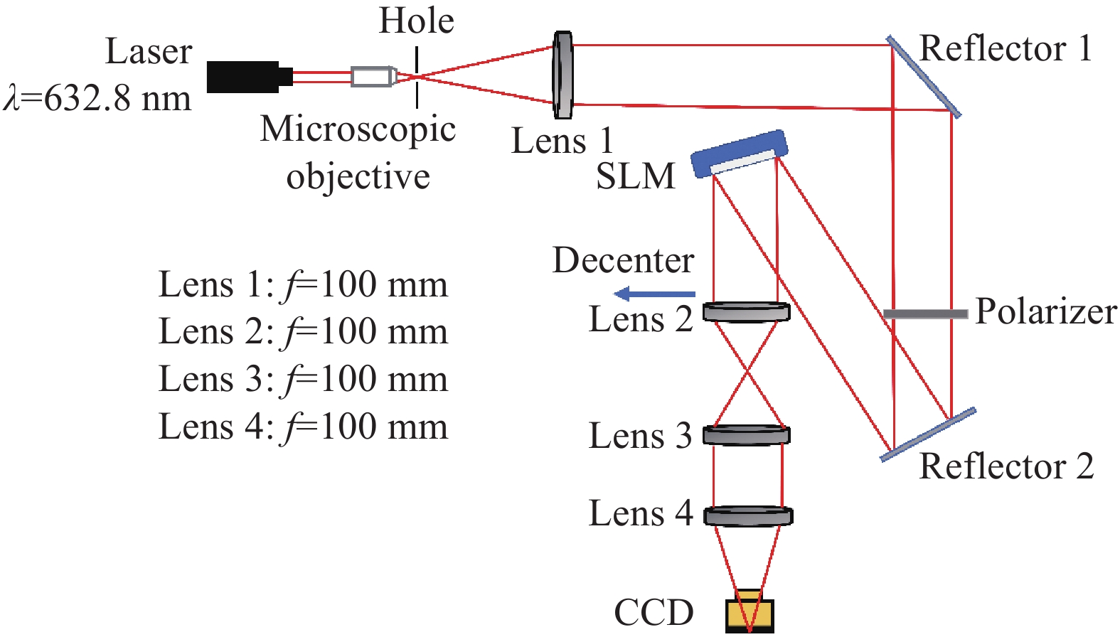
自由曲面本质上可看作一波前调制器件,当采用SLM加载自由曲面对应的相位调制图时,即可在实验上实现与自由曲面相同的波前调制效果,达到像差补偿的目的,按照图3所搭建的实验系统示意图如图8所示。

图 8 基于SLM的望远偏心系统像差补偿实验示意图
Figure 8. Schematic diagram of aberration compensation experiment for telescopic eccentric system based on SLM
当反射式自由曲面的表面起伏变化较小且与入射光束夹角较小时,光束经过自由曲面后改变的光程量可近似看作其表面矢高的2倍。表3所示为自由曲面各项系数值均很小,意味着其表面起伏程度很小;且自由曲面与入射光束夹角仅为4.6°,故其对于光束光程的改变量可近似处理为2倍面形矢高值。由此计算出两种方法优化设计出的自由曲面相位调制灰度图如图9所示。

图 9 两种方法优化出的自由曲面相位图。(a) NAT优化;(b) SAT优化
Figure 9. Phase maps of freeform surfaces optimized by two methods. (a) NAT optimization; (b) SAT optimization
利用CCD拍摄SLM加载相位灰度图前后的光斑,以此来反映系统的像差补偿情况和像质,其结果如图10所示。

图 10 补偿望远偏心系统像差实验光斑图。(a)补偿前;(b) NAT优化法补偿后;(c) SAT优化法补偿后
Figure 10. Experimental spot patterns of the eccentric telescope system. (a) Before compensation; (b) After compensation by NAT optimization method; (c) After compensation by SAT optimization method
从图10中发现,采用设计自由曲面补偿像差后,光斑的形状趋于更加规则,对称性提升,且光斑尺寸有所减小。为了更加准确定量分析补偿前后光斑大小,分别计算了像差补偿前后光斑RMS半径大小。其中,补偿前的RMS半径为0.057 mm,当采用NAT优化法补偿后,光斑半径减小至0.025 mm,而SAT优化补偿后的光斑RMS半径为0.027 mm,略大于NAT优化法的结果。
通过上述仿真以及实验分析研究发现,对于望远偏心系统实例,基于矢量像差理论的优化设计方法,能够成功优化出具有良好像差补偿效果的自由曲面,且相较于传统的标量像差理论优化方法,其优化设计出的自由曲面具备着更优的像差补偿效果,以此能更好地实现提升成像系统像质的目标。
-
文中基于矢量像差理论,介绍了一种用以补偿成像系统像差的自由曲面优化设计方法。为了研究该方法的优化效果,利用其优化设计了望远偏心系统的像差补偿自由曲面,并借助SLM开展了像差补偿实验研究。仿真设计结果显示,该方法优化设计出的自由曲面,有效补偿了望远偏心系统的像差,优化后系统波像差显著减小,像面处的光斑形状和尺寸均有较大改善,且MTF曲线也优于补偿前的结果,系统的像质大大提升。在此基础上,利用SLM加载像差补偿自由曲面相位灰度图开展像差补偿实验,实验结果也表明了优化设计出的自由曲面,具有非常良好的像差补偿效果,极大地提高了系统成像质量。不仅如此,通过与传统标量像差理论优化法优化后的结果对比研究发现,对于成像系统存在的像差,基于矢量像差理论的优化设计方法能得到补偿效果更优的自由曲面。
故而,其在通过优化设计自由曲面,实现成像系统像差补偿和像质优化,以及对光学系统波像差特性精准调控方面,具有一定的应用价值和研究意义。例如,除传统成像光学系统设计应用以外,在视光学这一交叉研究领域,人眼角膜地形图常用Zernike型自由曲面表征,采用基于矢量像差理论的优化设计方法对角膜的面形结构优化,不仅可构造出与实际人眼波像差特性高度吻合的个性化人眼模型,还可借助该模型研究人眼中存在的各种像差对视觉质量的影响机制,以此指导角膜屈光手术中角膜的切削方式和切削量,实现术后人眼拥有最佳视觉质量的目标。然而,由于矢量像差理论本质上存在一定的近似性[16],对于大视场系统的像差计算存在一定误差,因此对于该情况的校正方法有待进一步研究。
Application of nodal aberration theory in aberration compensation of the imaging system (invited)
-
摘要: 随着应用光学领域的蓬勃发展,对于成像光学系统的像质需求越来越高。自由曲面的多设计自由度使其具有优异的像差补偿能力,常被用于高效像差补偿器件,而设计出具有良好像差补偿效果的自由曲面是提升系统像质的关键。这里基于矢量像差理论,介绍了一种针对成像系统像差补偿的Zernike型自由曲面设计方法。并以望远偏心系统作为实例,利用所提出方法设计了该系统的像差补偿自由曲面,并借助空间光调制器开展实验研究。仿真与实验结果均表明,所提出方法能够得到有效补偿望远偏心系统像差的自由曲面,像差补偿后光斑尺寸降低至补偿前的43.9%,其像差补偿效果优于传统标量像差理论优化法设计结果,该方法在自由曲面成像系统设计方面具有一定的应用研究价值。Abstract:
Objective With the flourishing development of the applied optics, there are higher and higher requirements for the imaging quality of the optical system. With multiple design degrees of freedom, the freeform surface has excellent aberration compensation capability and is widely applied in the imaging system. Thus, it is very important to select a suitable design method and successfully design a freeform surface which can effectively compensate the aberrations. Considering the design requirement of compensating aberrations, it is very appropriate to choose the design methods guided by aberration theory. Nevertheless, the optimization and design method based on classical scalar aberration theory (SAT) may not give a good result because it is mainly applicable to rotational symmetric systems and there is aberration characterization error when the SAT method is used in a non-rotational symmetric system. What's different is that the nodal aberration theory (NAT) can accurately provide the relationship between wave aberration and various terms of Zernike type freeform surfaces. So, if adopting the optimization method guided by NAT, a freeform surface with better aberration compensation ability may be attained. Methods Firstly, on the basis of the wavefront aberration distribution from Zernike type freeform given by NAT, combined with self-developed iterative solution algorithm, a freeform surface optimization and design method guided by NAT is introduced in this paper. Secondly, in order to investigate the NAT optimization method's effect, a decentered telescope system is built as an example and the proposed method is utilized to optimize the freeform surface to compensate the aberrations of the decentered telescope system. Moreover, the aberration compensation experiment for the decentered telescope system is conducted by SLM loading freeform surface phase maps. Finally, the simulation and experimental results demonstrate that the freeform surface optimized by NAT method has better aberration compensation ability compared with that optimized by SAT method. Results and Discussion Firstly, after clarifying the aberration characteristics of the decentered telescope system (Fig.4), the aberration compensation freeform surfaces are optimized and designed by NAT method and SAT method respectively. The optimized result shows that the wavefront aberrations of this system reduce sharply (Fig.5). Compared to SAT optimization method's result, the residual aberration is significantly smaller by NAT optimization (Fig.5). Secondly, according to the simulation spot shape and RMS radius at the image surface, it is also found that the spot size of the system has smaller RMS radius optimized by NAT method (Fig.6). Then, the MTF curve indicates the optimized decentered telescope system by NAT method has better imaging quality after the aberration compensation freeform surface is introduced (Fig.7). Finally, by means of the SLM loading optimized freeform surfaces phase maps, the experiment on compensating the aberration of the decentered telescope system is carried out (Fig.8). The experimental results also demonstrate that the aberration of the system could be effectively compensated by freeform surface (Fig.10), and the surface optimized by NAT method has stronger aberration compensation ability. Thus, combined with simulation and experimental results, it is concluded that the NAT optimization method has better performance in optimizing freeform surfaces for aberration compensation and image quality improvement. Conclusions Aiming at the optimization and design of the aberration compensation freeform surface for the imaging system, a NAT optimization method is investigated in this paper. In order to explore this method's effect and compare with traditional SAT optimization method, these two methods are used to optimize the freeform surfaces for compensating the aberration of the decentered telescope system. More than that, an aberration compensation experiment for the decentered telescope is also carried out through SLM loading freeform surfaces phase maps, which could realize the same wavefront modulation effect as the freeform surfaces. Both simulation and experimental results show that better aberration compensation and imaging quality improvement effect can be achieved by using the NAT optimization method. Moreover, the proposed NAT optimization method also has great potentials in many applications, such as building individual optical model of human eye, evaluating visual quality of refractive surgery and optimizing the corneal removals for refractive surgeries, which are typical research issues in optometry. -
Key words:
- applied optics /
- aberration compensation /
- nodal aberration theory /
- freeform surface
-
图 1 自由曲面位于非光阑处光瞳矢量$ \overrightarrow \rho ' $示意图
Figure 1. Schematic diagram of the pupil vector $ \overrightarrow \rho ' $ when a freeform surface located at a non-aperture location
图 2 基于矢量像差理论的自由曲面优化迭代算法流程图
Figure 2. Flowchart of iterative algorithm for freeform surface optimization based on nodal aberration theory
图 3 自由曲面望远偏心系统仿真示意图
Figure 3. Simulation diagram of freeform surface telescopic eccentric system
图 4 望远偏心系统波像差分布图 ($ {{\lambda = 632}}{\text{.8 nm}} $)
Figure 4. Wave aberration distribution map of the telescopic eccentric system ($ {{\lambda = 632}}{\text{.8 nm}} $)
图 5 优化前及两种方法优化后望远偏心系统波像差分布图($ \lambda = $$ 632{\text{.8 nm}} $)
Figure 5. Wave aberration distribution map of the eccentric telescope system before and after optimization by two methods ($ {{\lambda = 632}}{\text{.8 nm}} $)
图 6 优化前以及两种方法优化后望远偏心系统仿真光斑图。(a)优化前;(b) NAT优化后;(c) SAT优化后
Figure 6. Light spot patterns of the eccentric telescope system before and after optimization by two methods. (a) Before optimization; (b) After NAT optimization; (c) After SAT optimization
图 7 优化前及两种方法优化后系统像面处MTF曲线
Figure 7. MTF curve at the image plane of the system before and after optimizing by two methods
图 8 基于SLM的望远偏心系统像差补偿实验示意图
Figure 8. Schematic diagram of aberration compensation experiment for telescopic eccentric system based on SLM
图 9 两种方法优化出的自由曲面相位图。(a) NAT优化;(b) SAT优化
Figure 9. Phase maps of freeform surfaces optimized by two methods. (a) NAT optimization; (b) SAT optimization
图 10 补偿望远偏心系统像差实验光斑图。(a)补偿前;(b) NAT优化法补偿后;(c) SAT优化法补偿后
Figure 10. Experimental spot patterns of the eccentric telescope system. (a) Before compensation; (b) After compensation by NAT optimization method; (c) After compensation by SAT optimization method
表 1 初级像散、离焦以及初级彗差项对应的Fringe Zernike项及系数
Table 1. Fringe Zernike terms and coefficients corresponding to primary astigmatism, defocusing, and primary coma terms
Wave aberration terms Corresponding Zernike terms and coefficients Primary astigmatism $ \begin{gathered} {\overrightarrow Z _{5/6}},{\alpha ^2}{\overrightarrow C _{5/6}} \\ {\overrightarrow Z _{7/8}},3{\alpha ^2}\left( {{{\overrightarrow C }_{7/8}}\overrightarrow H } \right) \\ {Z_9},12{\alpha ^2}{\beta ^2}\left( {{C_9}{{\overrightarrow H }^2}} \right) \\ {\overrightarrow Z _{10/11}},3{\alpha ^3}\beta \left( {{{\overrightarrow C }_{10/11}}{{\overrightarrow H }^ * }} \right) \\ {\overrightarrow Z _{12/13}},\left[ {12{\alpha ^2}{\beta ^2}\left( {{{\left| {\overrightarrow H } \right|}^2}{{\overrightarrow C }_{12/13}}} \right) - 3{\alpha ^2}{{\overrightarrow C }_{12/13}}} \right] \\ \end{gathered} $ Defocus $\begin{array}{l}{Z}_{4},{\alpha }^{2}{C}_{4}\\ {\overrightarrow{Z} }_{7/8},3{\alpha }^{2}\beta \left({\overrightarrow{C} }_{7/8}\cdot \overrightarrow{H}\right)\\ {Z}_{9},12{\alpha }^{2}{\beta }^{2}{C}_{9}(\overrightarrow{H}\cdot \overrightarrow{H})\\ {\overrightarrow{Z} }_{12/13},6{\alpha }^{2}{\beta }^{2}\left({\overrightarrow{C} }_{12/13}\cdot {\overrightarrow{H} }^{2}\right)\end{array}$ Primary coma $ \begin{gathered} {\overrightarrow Z _{7/8}},{\alpha ^2}{\overrightarrow C _{7/8}} \\ {Z_9},8{\alpha ^3}\beta \left( {{C_9}\overrightarrow H } \right) \\ {\overrightarrow Z _{12/13}}{\text{,4}}{\alpha ^3}\beta \left( {{{\overrightarrow C }_{12/13}}{{\overrightarrow H }^ * }} \right) \\ \end{gathered} $  下载: 导出CSV
表 2 自由曲面补偿望远偏心系统像差仿真参数表
Table 2. Simulation parameter table of freeform surface compensating telescopic eccentric system’s aberration
Surface Type Radius/mm Thickness/mm Glass Refraction/Reflex Semi-diameter/mm Decenter/Tilt Object Sphere Inf Inf - Refraction - - Stop Sphere Inf 470.00 - Refraction 4.00 - 2 Zernike Inf −283.00 - Reflex 4.10 Tilt 4.6° 3 Sphere −51.68 −5.00 K9 Refraction 12.70 Decenter 2 mm 4 Sphere Inf −197.50 - Refraction 12.70 - 5 Sphere −51.68 −5.00 K9 Refraction 12.70 - 6 Sphere Inf −71.00 - Refraction 12.70 - 7 Sphere −51.68 −5.00 K9 Refraction 12.70 - 8 Sphere Inf −96.23 - Refraction 12.70 - Image Sphere Inf 0.00 - Refraction 1.00 -
下载: 导出CSV
表 3 两种方法优化设计出补偿望远偏心系统像差自由曲面各项系数
Table 3. Optimized various coefficients of freeform surfaces to compensate the telescopic eccentric system’s aberration by two methods
Standard Zernike terms Z4 Z5 Z6 Z7 Z8 SAT 1.1150e-4 8.5520e-5 0 0 −1.4553e-4 NAT 9.9357e-5 1.1608e-4 0 0 −1.5360e-4
下载: 导出CSV
-
[1] Wu Rengmao, Yang Lin, Ding Zhanghao, et al. Precise light control in highly tilted geometry by freeform illumination optics [J]. Optics Letters, 2019, 44(11): 2887-2890. doi: 10.1364/OL.44.002887 [2] Zhu Zhengbo, Wei Shili, Fang Zichao, et al. Freeform illumination optics design for extended LED sources through a localized surface control method [J]. Optics Express, 2022, 30(7): 11524-11535. doi: 10.1364/OE.453571 [3] Hou Wei, Zhu Jun, Yang Tong, et al. Construction method through forward and reverse ray tracing for a design of ultra-wide linear field of view off-axis freeform imaging systems [J]. Journal of Optics, 2015, 17(5): 055603. doi: 10.1088/2040-8978/17/5/055603 [4] 蒋婷婷, 冯华君, 李奇. 自由曲面变焦的内调焦式光学系统设计[J]. 红外与激光工程, 2021, 50(4): 20200290. doi: 10.3788/IRLA20200290 Jiang Tingting, Feng Huajun, Li Qi. Design on internal focusing optical system with zoom lens of freeform [J]. Infrared and Laser Engineering, 2021, 50(4): 20200290. (in Chinese) doi: 10.3788/IRLA20200290 [5] 毛姗姗, 李艳秋, 刘克, 等. 高数值孔径自由曲面极紫外光刻物镜光学设计[J]. 红外与激光工程, 2019, 48(8): 814002-0814002(7). doi: 10.3788/IRLA201948.0814002 Mao Shanshan, Li Yanqiu, Liu Ke, et al. Optical design of high numerical aperture extreme ultraviolet lithography objective with freeform surfaces [J]. Infrared and Laser Engineering, 2019, 48(8): 814002. (in Chinese) doi: 10.3788/IRLA201948.0814002 [6] Xu Chen, Cheng Dewen, Chen Jinjin, et al. Design of all-reflective dual-channel foveated imaging systems based on freeform optics [J]. Applied Optics, 2016, 55(9): 2353-2362. doi: 10.1364/AO.55.002353 [7] Cheng Dewen, Duan Jiaxi, Chen Hailong, et al. Freeform OST-HMD system with large exit pupil diameter and vision correction capability [J]. Photonics Research, 2022, 10(1): 21-32. doi: 10.1364/PRJ.440018 [8] 陈炳旭, 廖志远, 操超, 等. 大视场大相对孔径自由曲面成像系统设计[J]. 红外与激光工程, 2020, 49(8): 20200005. doi: 10.3788/IRLA20200005 Chen Bingxu, Liao Zhiyuan, Cao Chao, et al. Design of the freeform imaging system with large field of view and large relative aperture [J]. Infrared and Laser Engineering, 2020, 49(8): 20200005. (in Chinese) doi: 10.3788/IRLA20200005 [9] Volatier Jean-Baptiste, Druart Guillaume. Differential method for freeform optics applied to two-mirror off-axis telescope design [J]. Optics Letters, 2019, 44(5): 1174-1177. doi: 10.1364/OL.44.001174 [10] Nie Yunfeng, Mohedano Ruben, Benitez Pablo, et al. Multifield direct design method for ultrashort throw ratio projection optics with two tailored mirrors [J]. Applied Optics, 2016, 55(14): 3794-3800. doi: 10.1364/AO.55.003794 [11] Fuerschbach Kyle, Rolland Jannick P, Thompson Kevin P. A new family of optical systems employing polynomial surfaces [J]. Optics Express, 2011, 19(22): 21919-21928. doi: 10.1364/OE.19.021919 [12] Yang Tong, Cheng Dewen, Wang Yongtian. Direct generation of staring points for freeform off-axis three-mirror imaging system design using neural network based deep-learning [J]. Optics Express, 2019, 27(12): 17228-17238. doi: 10.1364/OE.27.017228 [13] Cheng Dewen, Wang Yongtian, Hua Hong, et al. Design of an optical see-through head-mounted display with a low f-number and large field of view using a freeform prism [J]. Applied Optics, 2009, 48(14): 2655-2668. doi: 10.1364/AO.48.002655 [14] Fuerschbach Kyle, Rolland Jannick P, Thompson Kevin P. Extending nodal aberration theory to include mount-induced aberrations with application to freeform surfaces [J]. Optics Express, 2012, 20(18): 20139-20155. doi: 10.1364/OE.20.020139 [15] Fuerschbach Kyle, Rolland Jannick P, Thompson Kevin P. Theory of aberration fields for general optical systems with freeform surfaces [J]. Optics Express, 2014, 22(22): 26585-26606. doi: 10.1364/OE.22.026585 [16] Yang Tong, Zhu Jun, Jin Guofan. Nodal aberration properties of coaxial imaging systems using Zernike polynomial surfaces [J]. JOSA A, 2015, 32(5): 822-836. doi: 10.1364/JOSAA.32.000822 [17] Yang Tong, Cheng Dewen, Wang Yongtian. Aberration analysis for freeform surface terms overlay on general decentered and tilted optical surfaces [J]. Optics Express, 2018, 26(6): 7751-7770. doi: 10.1364/OE.26.007751 -

 点击查看大图

计量
- 文章访问数: 249
- HTML全文浏览量: 45
- PDF下载量: 66
- 被引次数: 0

