


-
自20世纪60年代初期激光器问世以来,由于激光具有良好的单色性、方向性以及高能量密度等优点,人们广泛地探索了其应用价值,到目前为止在激光驱动核聚变、激光加工、激光医疗[1−2]以及光刻等领域发挥了不可替代的作用。但是部分激光束的输出光束能量分布具有非均匀性,难以满足实际的应用需求,所以需要进行激光光束整形,对其光强分布和相位进行调制[3]。
常见的激光光束整形方法有双折射透镜法、微透镜阵列法、液晶空间光调制器法[4]、非球面透镜法[5]、自由曲面光学元件法等[6],其中自由曲面光学元件具有耐高功率激光辐照和光谱适用范围广的特性,可应用于高功率激光光束的整形。近年来,精密加工技术快速发展,使得早期由于无法加工而应用受限的自由曲面光学元件受到业界的青睐。
基于自由曲面的高斯光束整形系统设计方法最早由Frieden、Kreuze等人提出,基本思想是基于能量守恒定律建立入射光线与出射光线的坐标映射关系,再通过Snell定律和映射关系建立两个曲面面形的微分方程[7],对方程进行数值求解可得到曲面面形分布,但是该方法求解需要系统结构参数满足一定的近似条件,不适用于结构紧凑的系统的设计。后续人们提出了许多光束整形方法,如常微分方程法[8]、剪裁法[9]、SMS法[10−12]、蒙日安培方程法[13−15]、偏微分方程法[16]等,上述方法虽然能够实现无对称性的复杂照明设计,但仍然存在映射关系与矢高方程求解困难的问题。为了降低设计难度,Wang Lin[17]等人提出了一种变量可分离的映射策略进行自由曲面设计的方法,该方法能通过迭代对求解过程中离散点处的法矢偏差进行实时修正,提升单个自由曲面的设计精度,但并未提及如何设计双自由曲面光束整形系统。利用变量可分离的映射法用于双自由曲面的设计时需要引入一个虚拟平面来耦合两个自由曲面,虚拟平面的作用是替代未知的第二个自由曲面以求解第一个自由曲面的出射光线及其特征向量,但是虚拟面与第二个自由曲面并不完全重合,其不重合度会造成所设计出的两个自由曲面耦合不良,特别是在结构紧凑(双自由曲面镜间距短)和扩束倍率大的光束整形系统中,导致光束整形效果不理想。
为了解决虚拟面引入带来的耦合不良问题,文中提出了基于虚拟面迭代法的自由曲面光束整形系统的设计方法。在第二个自由曲面顶点处设置一个虚拟平面,借助变量可分离的映射策略分别求解两个自由曲面上的离散点,并通过不断迭代更新该虚拟面来逼近第二个自由曲面的真实面形。此外,定量分析了引入虚拟面造成的不重合度的大小以及双自由曲面光束整形系统的结构参数与不重合度之间的相关关系,最后通过实例仿真验证了虚拟面迭代法的有效性。
-
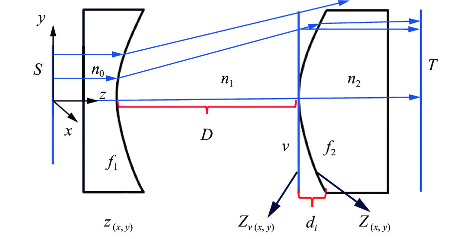
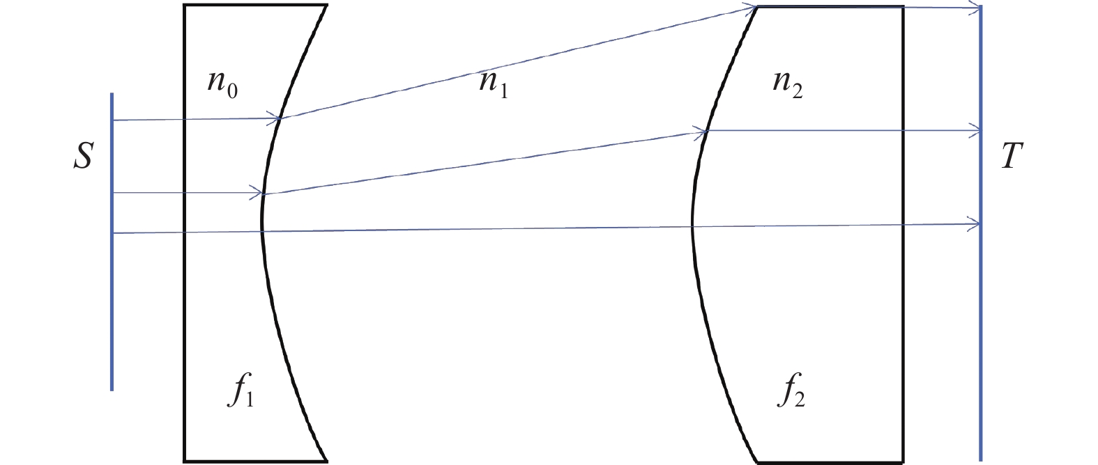
非球面可以看作自由曲面的一种旋转对称的特殊情况,此处以双自由曲面透镜将圆形高斯光束整形为圆形平顶光束为例,系统结构如图1所示,${f_1}$、${f_2}$分别为两个自由曲面,${n_0}$、${n_1}$,${n_2}$分别为第一个自由曲面镜、空气以及第二个自由曲面镜的折射率,$S$为入射光束截面,$T$为目标面,线条代表光线在整个系统中的路径。

图 1 同轴式双自由曲面光束整形系统结构示意图
Figure 1. Schematic diagram of a coaxial double free-form beam shaping system
根据能量守恒定律,有:
$$ \int\limits_0^{2\pi } {{\mathrm{d}}\theta } \int\limits_0^{{r_{\max }}} {{I_{{\rm{in}}}}(r)} r{\mathrm{d}}r = \int\limits_0^{2\pi } {{\mathrm{d}}\theta } \int\limits_0^{{R_{\max }}} {{I_{{\rm{out}}}}(R)} R{\mathrm{d}}R = E $$ (1) 式中:${I_{{\rm{in}}}}$为入射光强;$r$为光源光束的径向位置;${r_{\max }}$为光源光束切趾范围;${I_{{\rm{out}}}}$为目标面光束光强;$R$为目标面的径向位置;${R_{\max }}$为目标面切趾范围;$E$为目标面切趾范围内的总能量。
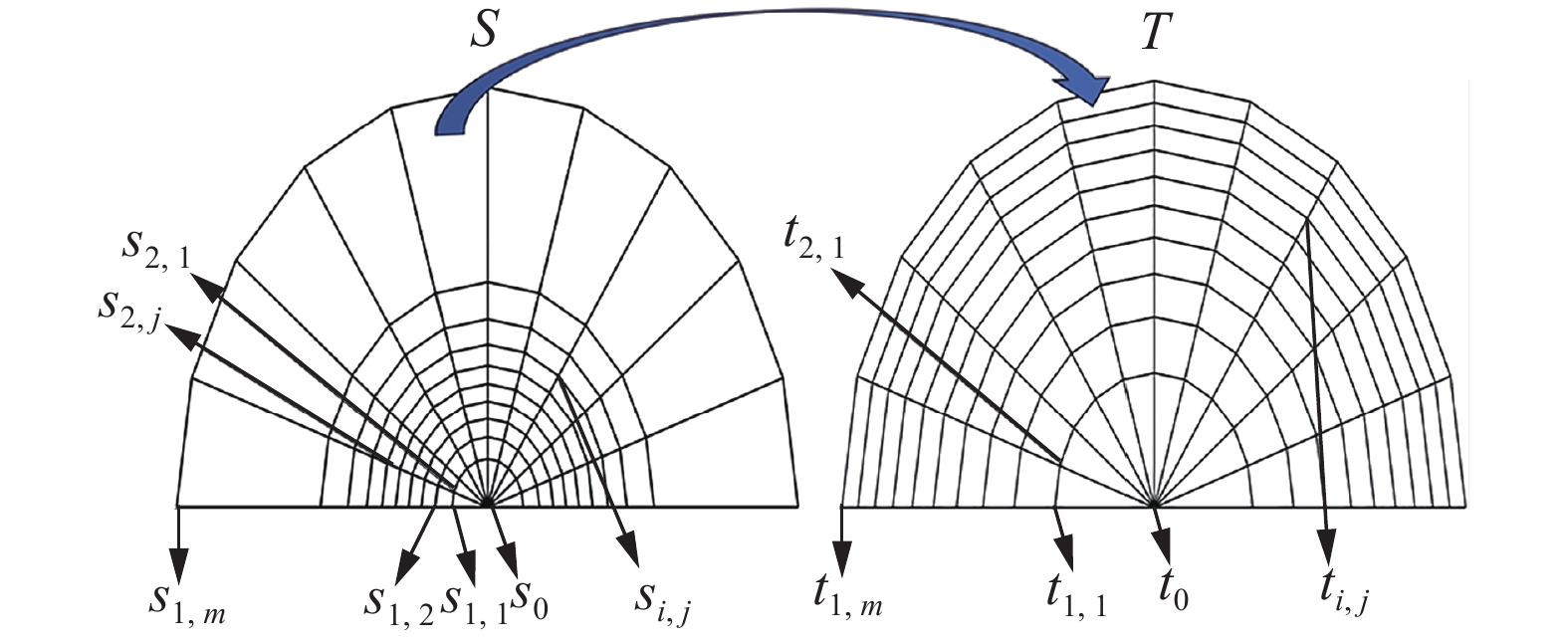
分别将入射光束截面和目标面按等能量划分,根据边缘光线原理[18],入射光束每个网格内的光束经过整形系统后出射到目标面对应的网格内,即图2中光源面与目标面每个网格内的能量对应相等且为:
$$ {e_s} = {e_t} = \frac{E}{M} $$ (2) 式中:M为网格数量;${e_s}$与${e_t}$分别为光源面与目标面每个网格内的能量。
网格之间的交点代表采样点,两个面的采样点亦一一对应,如图2所示。

图 2 输入与输出光束之间的能量映射网格示意图
Figure 2. Grid diagram of energy mapping between the input beam and output beam
-
自由曲面离散点的具体求解过程:利用入射和出射光线向量结合Snell定律反解离散点法向量进而得到该点处的切平面,当划分的网格足够小,即采样点数量足够多时,相邻采样点的出射光线与该切平面的交点可近似作为对应自由曲面上的离散点[17],重复上述步骤即可求出自由曲面上所有的离散点,现称该方法为种子曲线法[19]。假设初始点为${P}_{1,1}$,该点处的法向量为$\overrightarrow {{N_{1,1}}} $,切平面为${M}_{1,1}$,相邻入射光线$\overrightarrow{{i}_{1,2}}$从入射光束截面采样点${s}_{1,2}$射出,与${M}_{1,1}$相交于点${P}_{1,2}$,该点处出射光束为$\overrightarrow{{o}_{1,2}}$,到达目标面采样点${t}_{1,2}$法向量为$\overrightarrow{{N}_{1,2}}$,求解过程如图3(a)、(b)所示。在设计含有两个自由曲面的系统时,两个自由曲面上的所有离散点均可用种子曲线法来进行求解。
图3(a)中的向量分别可表示为:
$$ \overrightarrow{{i}_{1\text{,}2}}=\frac{\overrightarrow{{P}_{1\text{,}2}-{s}_{1\text{,}2}}}{\left|\overrightarrow{{P}_{1\text{,}2}-{s}_{1\text{,}2}}\right|} $$ (3) $$ \overrightarrow{{o}_{1\text{,}2}}=\frac{\overrightarrow{{t}_{1\text{,}2}-{P}_{1\text{,}2}}}{\left|\overrightarrow{{t}_{1\text{,}2}-{P}_{1\text{,}2}}\right|} $$ (4) $$ \overrightarrow{{N}_{1\text{,}2}}=\frac{({n}_{1}\overrightarrow{{o}_{1\text{,}2}}-{n}_{0}\overrightarrow{{i}_{1\text{,}2}})}{\sqrt{{n}_{1}{}^{2}+{n}_{0}{}^{2}+2{n}_{0}{n}_{1}(\overrightarrow{{o}_{1\text{,}2}}\cdot \overrightarrow{{i}_{1\text{,}2}})}} $$ (5) 且当采样点数量足够多时,对于相邻采样点的近似求解可表示为:
$$ (\overrightarrow{{P}_{1\text{,}2}-{P}_{1\text{,}1}})\cdot \overrightarrow{{N}_{1\text{,}1}}=0 $$ (6) 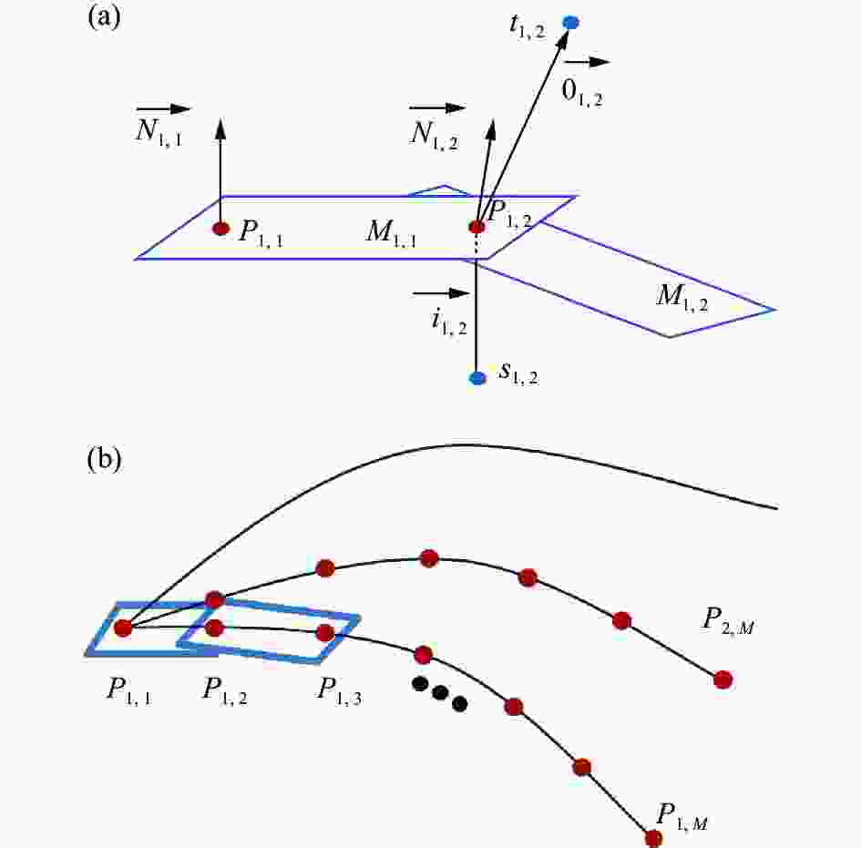
图 3 (a)自由曲面上相邻点求解方法示意图;(b)种子曲线法求解自由曲面上所有离散点示意图
Figure 3. (a) Schematic diagram of solving adjacent points on the free-form surface; (b) Schematic diagram of solving all discrete points of the free-form surface
-
如图1所示,将高斯光束整形为准直的平顶光束至少需要两个自由曲面,通常第一个用于重新分配辐照度,第二个用于相位调制,使光束准直。利用种子曲线法设计单个自由曲面时需要入射面和目标面的采样点映射关系为已知条件,因为运用Snell定律求解离散点处法向量时需要光线出射向量已知,如公式(5)所示,而光线出射向量由目标面采样点坐标和离散点坐标求得,如公式(4)所示。在设计双自由曲面系统时需要设置虚拟面来耦合两个自由曲面,因为第二个自由曲面是未知的,即第一个自由曲面的目标面未知,所以需要在第二个自由曲面顶点处预设虚拟平面来代替第二个自由曲面进行第一个自由曲面的求解,已知第一个自由曲面和整个系统的目标面即可进一步求解第二个自由曲面。显然,该虚拟面与第二个自由曲面并不完全重合,如图4所示,设计离轴双反光束整形系统时同理,如图5所示,${v_o}$为虚拟面。图4中虚拟面$v$上每个点与第二个自由曲面${f_2}$上对应点之间存在距离${d_i}$,且${d_i}$大小随离散点位置变化而变化,可表示为:
$$ {d_i} = Z(x,y) - {Z_v}(x,y) $$ (7) 式中:$Z(x,y)$为${f_2}$上离散点的$z$坐标;${Z_v}(x,y)$为虚拟面$v$上采样点的$z$坐标。
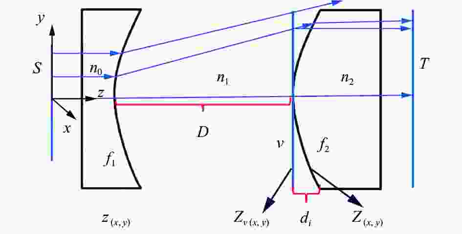
图 4 双自由曲光束整形系统设计过程中虚拟面与自由曲面面型的差异示意图
Figure 4. The difference between the virtual surface and the free-form surface in the design process of a double free-from beam shaping system

图 5 离轴反射式双自由曲面光束整形系统示意图
Figure 5. Schematic diagram of the off-axis two-mirror beam shaping system
由于距离${d_i}$的存在,实际从自由曲面${f_1}$上出射的光线并不会到达自由曲面${f_2}$上预设的位置,甚至会有边缘光线逸出的情况,即两个自由曲面耦合不良,最终会影响系统的整形效果,例如能量利用率和目标面辐照度均匀度不理想。易知,${d_i}$的大小与第二个自由曲面${f_2}$的面形有关,面形越平缓${d_i}$越小,面形垂度越大,${d_i}$也越大。
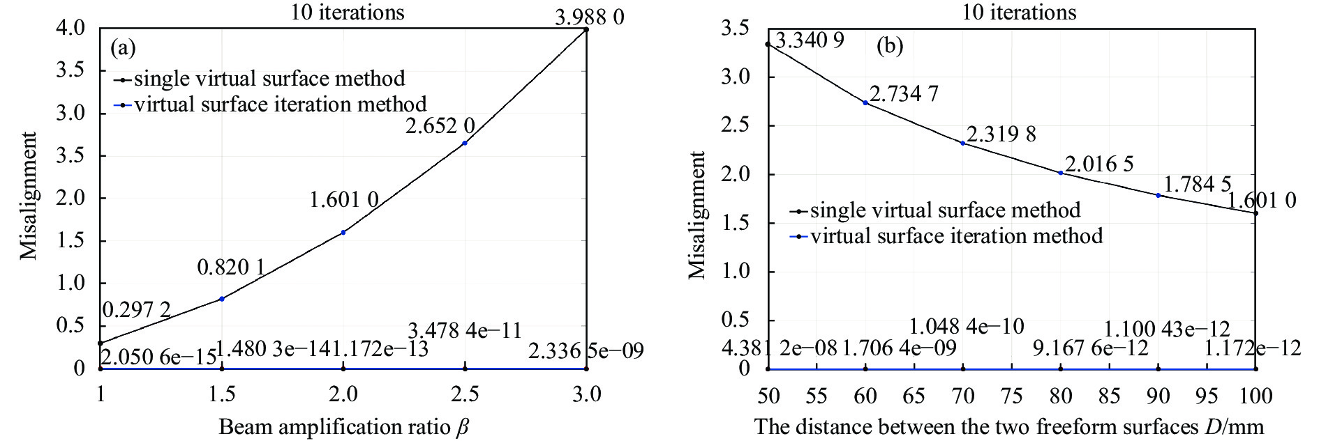
经分析,自由曲面面形与系统的扩束倍率$\beta $和两个曲面之间的轴向距离$D$有关,以自由曲面${f_2}$上所有离散点与虚拟面上所有对应点的坐标差之和除以采样点数量所得的$d'$作为不重合度的评价指标,分别控制变量,分析两个因素对不重合度的影响。上述参数中,$D$为图4中所示的透镜组的第二和第三个面的轴向距离,扩束倍率和不重合度可表示为:
$$ \beta = \frac{{{R_{\max }}}}{{{r_{\max }}}} $$ (8) $$ d' = \frac{{\sum\limits_1^n {{d_i}} }}{n} $$ (9) 式中:$n$为采样点数量。
假设入射光束束腰半径${\omega _0}$为5 mm,光束切趾范围$r$为10 mm,光束波长为1064 nm,光束切趾范围$r$上的采样点数为10000,自由曲面透镜基材为BK7并仅考虑材料对能量的吸收,当$D$为100 mm时,$\beta $与不重合度的关系如图6(a)所示;当$\beta $为2时,$D$与不重合度之间的关系如图6(b)所示。由图6(a)、(b)可得出结论:不重合度与整个光束整形系统的扩束倍率$\beta $正相关,与系统中两个自由曲面的轴向距离$D$负相关,所以单一虚拟平面法仅在特定的场景中适用,例如$\beta $为1或者$D$较大时,而在扩束倍率$\beta $较大,两个自由曲面的轴向距离$D$较小的情形中,该方法引入的不重合度较大,即单一虚拟面法不适用于结构紧凑和扩束倍率大的光束整形系统的设计。
为了降低虚拟面引入的不重合度的大小,考虑采用对虚拟面进行迭代的策略,现将该方法称为虚拟面迭代法 (VSI method),在设定系统初始点位置后,其主要步骤如下:
1) 过第二个自由曲面顶点设置虚拟平面;
2) 利用种子曲线法,根据系统入射光线和虚拟面求出第一个自由曲面的离散点坐标;
3) 利用从第一个自由曲面出射的光线和系统目标面求出第二个自由曲面的离散点坐标;
4) 将步骤3)所求出的第二个自由曲面作为虚拟面重新进行整个光束整形系统两个自由曲面离散点的计算,并利用公式(7)和公式(9)求解此次迭代的不重合度;
5) 重复步骤2)~4)直到不重合度远小于系统初始不重合度且逼近于0,一般迭代次数大于5次即可。

图 6 (a) 扩束倍率对不重合度的影响;(b) 两个自由曲面之间的轴向距离对不重合度的影响
Figure 6. (a) Influence of the beam amplification ratio on the misalignment; (b) Influence of the axial distance between two free-form surfaces on the misalignment
图7为迭代过程中虚拟面的矢高与曲率变化趋势示意图。初始虚拟面是一个平面,后续迭代过程中虚拟面均是曲面,且随着迭代过程的进行,虚拟面的矢高和曲率在偶数次迭代中大于第二个自由曲面的真实面形,在奇数次中小于第二个自由曲面的真实面形,但总体而言与第二个自由曲面的真实面形的差异逐渐减小。
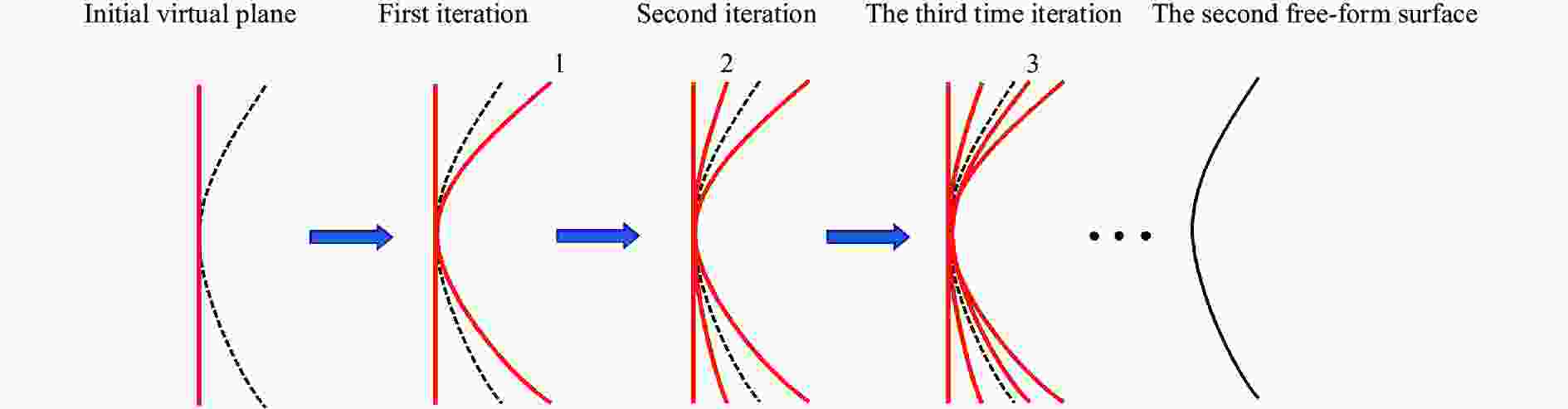
图 7 虚拟面迭代过程示意图
Figure 7. Diagram of the virtual surface iteration process
-
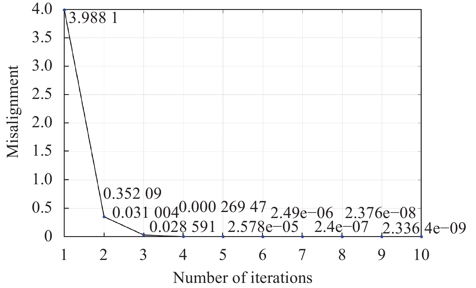
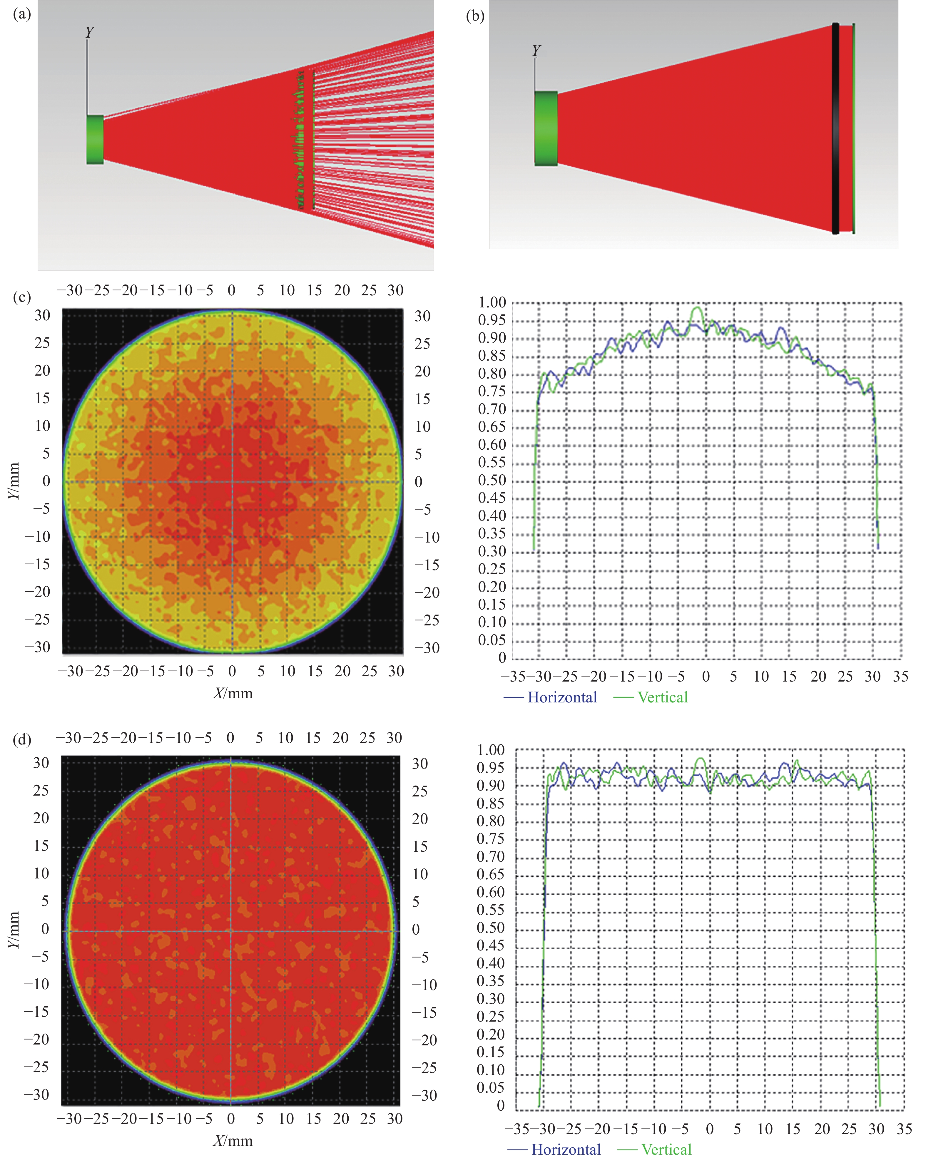
系统参数同1.3节,选取$D$为100 mm,$\beta $为3,用虚拟面迭代法设计光束整形系统,并计算每次迭代后的不重合度,结果如图8所示。易知,随着迭代次数增加,不重合度迅速逼近0,当迭代到第10次时,不重合度从初始时的3.9881减小到2.3364×10⁻⁹。利用Tracepro软件进行仿真分析,透镜基材为BK7,表面设置为全透膜,单一虚拟面法与虚拟面迭代法迭代10次所设计系统的仿真模拟图和目标面辐照度分布图如图9所示。
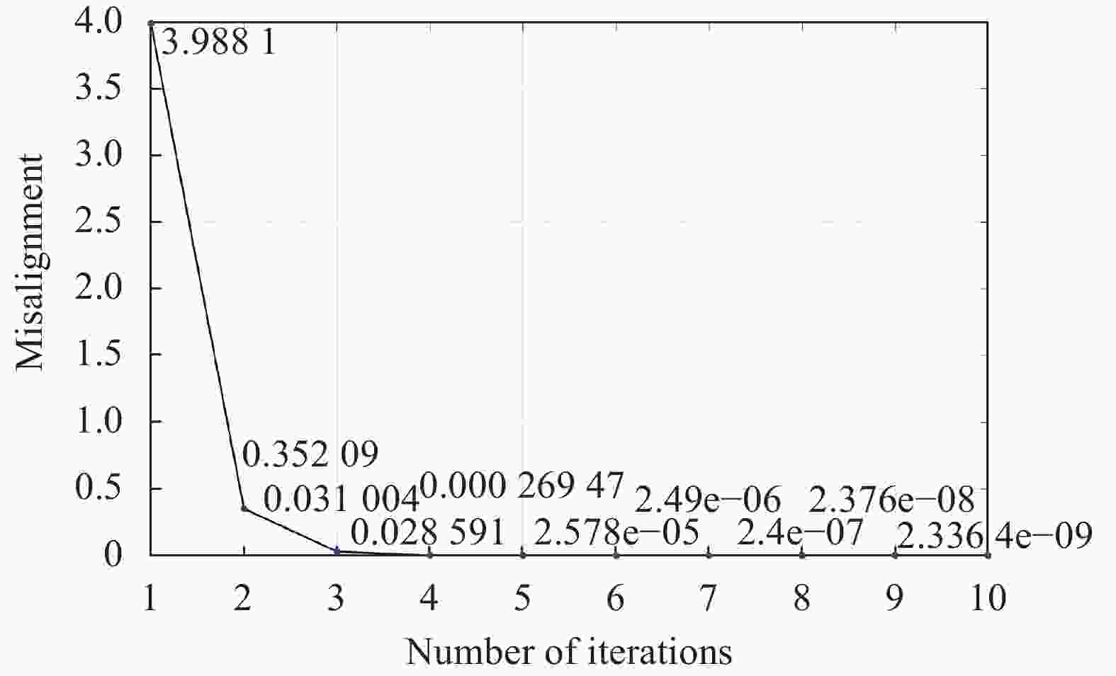
图 8 不重合度随迭代次数减小示意图
Figure 8. Misalignment decreases with the number of iterations
经计算,图9(c)所示光束整形系统仿真结果的辐照度均匀度为92.64%,能量利用率为90.859%。由Beer-Lambert定律可知,系统对于激光束的透过率约为99.2%,则激光损失的能量中,少部分被透镜材料所吸收,大部分由边缘逸散的光线造成,如图9(a)所示。图9(d)中由虚拟面迭代法所设计的光束整形系统仿真结果的辐照度均匀度为95.57%,能量利用率为99.789%。
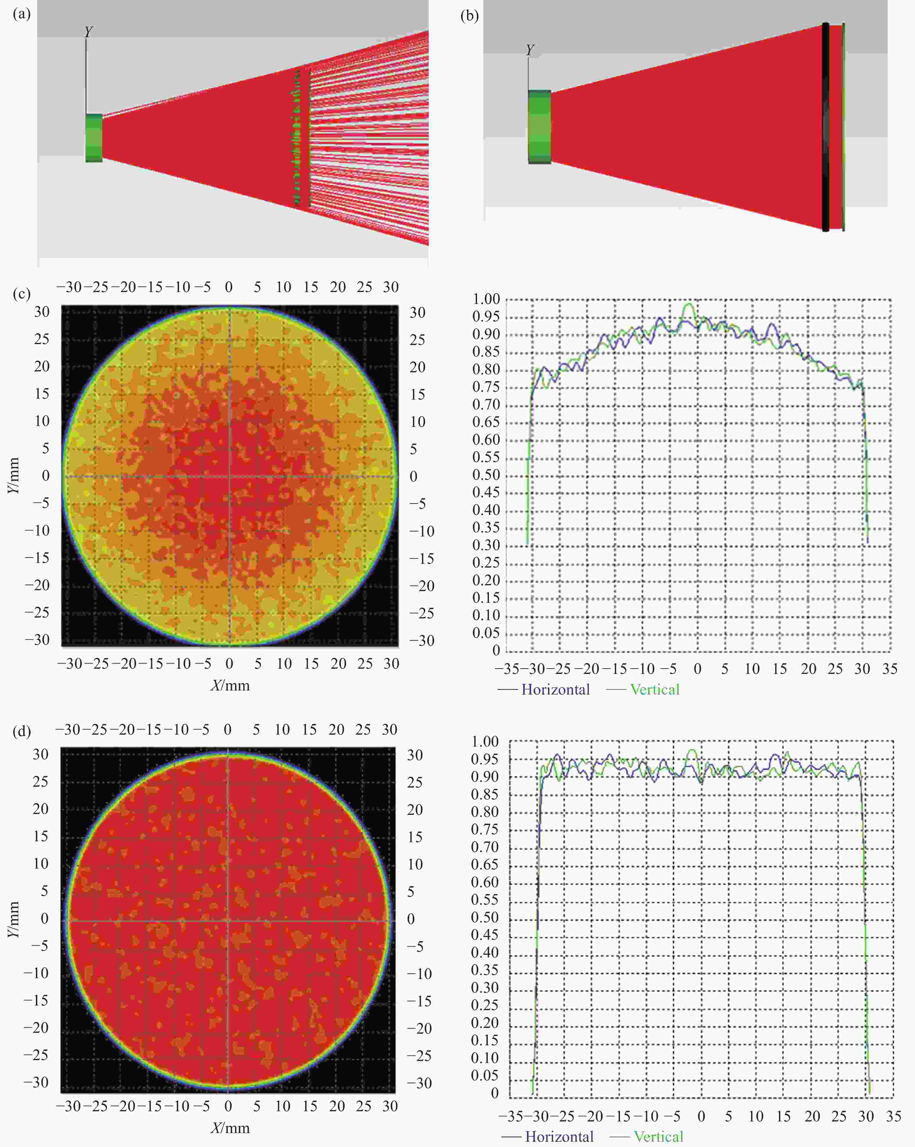
图 9 (a) 由单一虚拟面法设计的系统的光线追迹仿真图; (b) 由虚拟面迭代法设计的系统的光线追迹仿真图; (c) 由单一虚拟面法设计的系统的目标面辐照度仿真图; (d) 由虚拟面迭代法设计的系统的目标面辐照度仿真图
Figure 9. (a) Ray tracing simulation diagram of a system designed by the Single Virtual Surface method; (b) Ray tracing simulation diagram of a system designed by the VSI method; (c) Simulation diagram of the irradiance of the target surface of the system designed by the Single Virtual Surface method; (d) Simulation diagram of the irradiance of the target surface of the system designed by the VSI method
其中,辐照度均匀度$\varphi $、能量利用率$\eta $和透过率$\tau $的计算方法如下:
$$ RMS E = \sqrt {\sum\limits_{i = 1}^n {{{({E_{ri}} - {E_t})}^2}} /\sum\limits_{i = 1}^n {{{({E_t})}^2}} } $$ (10) $$ \varphi = (1 - RMS E) \times 100 {\text{%}} $$ (11) $$ \eta = \frac{{{E_{{\rm{out}}}}}}{{{E_{{\rm{in}}}}}} \times 100 {\text{%}} $$ (12) $$ \tau = \exp ( - \alpha \times l) $$ (13) 式中:$ {E_{ri}} $和$ {E_t} $分别为目标面入射的第$i$条光线对应的采样点的实际照度和平均照度值;${E_{{\rm{in}}}}$和${E_{{\rm{out}}}}$分别为入射光束总能量和目标面总能量;$\alpha $为材料对激光的吸收系数;$l$为材料厚度。
为了进一步验证虚拟面迭代法的有效性,用虚拟面迭代法迭代10次设计与图6(a)、(b)相同参数的所有光束整形系统,并计算它们的不重合度作对比分析,结果如图10(a)、(b)所示,可知相对于单一虚拟面法而言,虚拟面迭代法能有效降低不重合度。再对两种方法所设计的上述光束整形系统进行仿真分析,结果如表1和表2所示。可知虚拟面迭代法相比于单一虚拟面法能够有效提升所设计系统的光束整形效果,即提高辐照度均匀度和能量利用率,且对于扩束倍率越大和空间结构越紧凑的系统而言,光束整形效果的提升越明显。另外,结合图10与表1、表2可知,所设计光束整形系统的不重合度越低,该系统的光束整形效果越好。

图 10 (a) 两种方法所设计的不同扩束倍率的光束整形系统的不重合度对比图; (b) 两种方法所设计的不同轴向距离的光束整形系统的不重合度对比图
Figure 10. (a) Comparison diagram of misalignment of beam shaping system with different beam amplification ratios designed by the two methods; (b) Comparison diagram of misalignment of beam shaping system with different axial distances designed by the two methods
表 1 两种方法设计的不同扩束倍率的光束整形系统的仿真结果
Table 1. Simulation results of beam shaping systems with different beam amplification ratios designed by the two methods
Beam amplification ratio Single Virtual Surface method Virtual Surface Iteration method Irradiance uniformity Energy efficiency Irradiance uniformity Energy efficiency 1 95.79% 99.804% 96.25% 99.804% 1.5 95.24% 99.809% 96.23% 99.81% 2 95.22% 96.619% 95.80% 99.821% 2.5 94.03% 92.951% 95.76% 99.817% 3 92.64% 90.859% 95.57% 99.798% 表 2 两种方法设计的不同轴向距离的光束整形系统的仿真结果
Table 2. Simulation results of beam shaping systems with different axial distances designed by the two methods
Axial distance/mm Single Virtual Surface method Virtual Surface Iteration method Irradiance uniformity Energy efficiency Irradiance uniformity Energy efficiency 50 90.56% 92.201% 96.18% 99.801% 60 92.75% 97.541% 95.86% 99.794% 70 94.59% 99.772% 95.34% 99.788% 80 95.20% 99.780% 95.64% 99.826% 90 95.30% 99.820% 95.79% 99.823% -
该方法也同样适用于离轴双反光束整形系统的设计,但系统结构为离轴且计算离散点过程使用反射定律。分别用单一虚拟面法和虚拟面迭代法设计了一个离轴双反射光束整形系统。入射光束束腰半径${\omega _0}$为5 mm,入射光束切趾范围$r$为10 mm,目标面切趾半径$R$为50 mm,轴向距离$D'$为100 mm,离轴距离$L$为100 mm,光束波长为1064 nm,采样点数为1000×1000,反射镜基材为融石英,表面镀全反膜。单一虚拟面法所设计系统的目标面辐照度均匀度为90.53%,能量利用率为98.08%,虚拟面迭代法设计系统的目标面辐照度均匀度为94.80%,能量利用率为99.44%,它们的光线追迹和辐照度仿真度分别如图11(a)~(d)所示。

图 11 (a) 由单一虚拟面法设计的离轴双反光束整形系统的光线追迹仿真图; (b) 由虚拟面迭代法设计的离轴双反光束整形系统的光线追迹仿真图; (c) 由单一虚拟面法设计的离轴双反光束整形系统的目标面辐照度仿真图; (d) 由虚拟面迭代法设计的离轴双反光束整形系统的目标面辐照度仿真图
Figure 11. (a) Ray tracing simulation diagram of the off-axis two-mirror beam shaping system designed by the Single Virtual Surface method; (b) Ray tracing simulation diagram of the off-axis two-mirror beam shaping system designed by the VSI method; (c) Simulation diagram of the irradiance of the target surface of the off-axis two-mirror beam shaping system designed by the Single Virtual Surface method; (d) Simulation diagram of the irradiance of the target surface of the off-axis two-mirror beam shaping system designed by the VSI method
值得注意的是,在离轴双反光束整形系统中,除了扩束倍率和两个自由曲面之间的轴向距离以外,两个自由曲面的光轴之间的离轴距离$L$也是一个影响自由曲面面型的因素,如图5所示。采用和1.3节同轴系统相同的入射光束参数,扩束比为3,轴向距离为200 mm,设置不同的离轴距离$L$,分别以单一虚拟面法和虚拟面迭代法进行系统设计并计算不重合度,如图12所示。易知,不重合度与离轴距离成负相关关系,且虚拟面迭代法能有效降低系统不重合度。
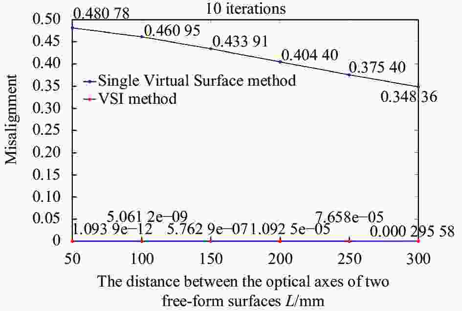
图 12 两种方法所设计的不同离轴距离的光束整形系统的不重合度对比图
Figure 12. Comparison diagram of misalignment of beam shaping system with different distances between optical axes designed by the two methods
-
文中提出了一种虚拟面迭代策略的由曲面光束整形系统设计方法。在双自由曲面光束整形系统的设计中,该方法的原理是根据种子曲线法对自由曲面上的离散点进行逐点计算,设置虚拟面并不断迭代来进行两个自由曲面的耦合,提升光束整形系统对于光束的整形效果。文中着重分析了不重合度与光束整形系统之间的相关关系,得出不重合度与光束整形系统扩束倍率以及空间结构紧凑程度呈正相关关系的结论。分别设计了同轴透射式和离轴双反射式的光束整形系统并利用仿真软件进行仿真分析,得到了较为理想的辐照度均匀度和能量利用率的出射光束,相对于单一虚拟面法设计的光束整形系统整形效果大幅提升,证明了虚拟面迭代法的有效性。该方法在激光加工、医疗、光信息处理等领域所需要的激光光束整形系统设计中具有重要的应用价值。
Design method of beam shaping system for double free-form surfaces based on Virtual Surface Iteration method
-
摘要: 双自由曲面光束整形系统可在不改变光束相位分布的情况下实现光束空间光强分布的按需调控,然而其需要设置虚拟平面来进行双自由曲面面形的求解。研究发现,传统单一虚拟面法在应用于结构紧凑和扩束倍率较大的系统时,存在设计不精准、整形效果差等缺陷,为此,提出了一种基于虚拟面迭代策略的双自由曲面光束整形系统设计方法。基于不同参数的同轴透射式和离轴反射式光束整形系统的数值仿真研究结果,表明该方法可有效规避传统虚拟面法的局限性。以将束腰半径为5 mm的高斯光束整形为半径30 mm的准直平顶光束的透射式双自由曲面光束整形系统为例,虚拟面迭代法所设计的光束整形系统将光强分布均匀性和能量利用率相对于单一虚拟面法而言分别提升了2.93%和8.93%。Abstract:
Objective The double free-form optical beam shaping system can adjust the spatial intensity distribution of the beam without altering its phase distribution. Still, it requires solving for the shape distribution of the double free-form optical surfaces by setting a virtual plane. This study reveals that applying the traditional single virtual surface method to design beam shaping systems with compact structures (short distance between double free-form optical elements) and large beam amplification (the ratio of the cutoff radius of the outgoing beam to the incident beam) ratios have some drawbacks, such as significant errors in solving for the double free-form optical surfaces and reduced shaping effectiveness, which generally includes the energy efficiency of the whole system for the beam and the irradiance uniformity of the beam after shaping. Methods This paper presents a method for designing a free-form optical beam shaping system based on a virtual surface iteration strategy and the concept of misalignment is proposed to evaluate the difference between the obtained second free-form surface and the virtual surface. The first step involves the creation of a virtual plane at the vertex of the second free-form surface and the virtual surface serves as the target surface of the beam exiting from the first free-form surface. Subsequently, all the discrete points on the first free-form surface can be obtained by using the virtual surface and Snell's law, in this case, all discrete points on the second free-form surface can be obtained by using Snell's law given the outgoing beam of the first free-form surface and the target surface of the whole beam shaping system. Finally, an iterative process updates the virtual surface to approximate the true shape of the second free-form surface. Results and Discussions The quantitative analysis examines the influence of the beam amplification ratio β and the axial distance D between the two optical elements on the misalignment between the virtual surface and the actual surface. A negative correlation is observed between β and misalignment, while a positive correlation exists between D and misalignment. Importantly, it is noticeable that with an increase in iterations, the value of misalignment rapidly approaches 0, thereby verifying the effectiveness of the Virtual Surface Iteration method. Two distinct beam shaping systems have been designed: a transmitted double free-form surfaces system and an off-axis two-mirror system. Simulation results demonstrate that both systems achieve over 95% irradiance uniformity (Tab.1) and more than 99% energy efficiency (Tab.1). Furthermore, employing the Single Virtual Surface method relatively enhances irradiance uniformity by 2.93% and energy efficiency by 8.930%. Conclusions This paper presents a design method for the beam shaping system of the double free-form surface based on a virtual surface iteration strategy. The proposed method employs ray tracing to calculate discrete points on the free-form surface. It utilizes the virtual surface iteration strategy to minimize the misalignment between the virtual and real surfaces. This approach ensures that the virtual surface continuously approaches the actual shape of the second free-form surface, thereby enhancing the coupling between the free-form surfaces in the beam shaping system. Additionally, this study analyzes the correlation between misalignment and parameters of the beam shaping systems, concluding that the misalignment is positively associated with both the beam amplification ratio and the compactness of the spatial structure of the system. Subsequently, simulation software is employed to design and simulate a coaxial transmission beam shaping system as well as an off-axis double-mirror beam shaping system. These simulations yield outgoing beams with ideal irradiance uniformity and energy efficiency. Compared to virtual plane methods, our proposed approach significantly improves shaping effects, thus validating its effectiveness in laser processing, medical treatment, optical information processing, and other fields requiring laser beam shaping systems. -
图 1 同轴式双自由曲面光束整形系统结构示意图
Figure 1. Schematic diagram of a coaxial double free-form beam shaping system
图 2 输入与输出光束之间的能量映射网格示意图
Figure 2. Grid diagram of energy mapping between the input beam and output beam
图 3 (a)自由曲面上相邻点求解方法示意图;(b)种子曲线法求解自由曲面上所有离散点示意图
Figure 3. (a) Schematic diagram of solving adjacent points on the free-form surface; (b) Schematic diagram of solving all discrete points of the free-form surface
图 4 双自由曲光束整形系统设计过程中虚拟面与自由曲面面型的差异示意图
Figure 4. The difference between the virtual surface and the free-form surface in the design process of a double free-from beam shaping system
图 5 离轴反射式双自由曲面光束整形系统示意图
Figure 5. Schematic diagram of the off-axis two-mirror beam shaping system
图 6 (a) 扩束倍率对不重合度的影响;(b) 两个自由曲面之间的轴向距离对不重合度的影响
Figure 6. (a) Influence of the beam amplification ratio on the misalignment; (b) Influence of the axial distance between two free-form surfaces on the misalignment
图 9 (a) 由单一虚拟面法设计的系统的光线追迹仿真图; (b) 由虚拟面迭代法设计的系统的光线追迹仿真图; (c) 由单一虚拟面法设计的系统的目标面辐照度仿真图; (d) 由虚拟面迭代法设计的系统的目标面辐照度仿真图
Figure 9. (a) Ray tracing simulation diagram of a system designed by the Single Virtual Surface method; (b) Ray tracing simulation diagram of a system designed by the VSI method; (c) Simulation diagram of the irradiance of the target surface of the system designed by the Single Virtual Surface method; (d) Simulation diagram of the irradiance of the target surface of the system designed by the VSI method
图 10 (a) 两种方法所设计的不同扩束倍率的光束整形系统的不重合度对比图; (b) 两种方法所设计的不同轴向距离的光束整形系统的不重合度对比图
Figure 10. (a) Comparison diagram of misalignment of beam shaping system with different beam amplification ratios designed by the two methods; (b) Comparison diagram of misalignment of beam shaping system with different axial distances designed by the two methods
图 11 (a) 由单一虚拟面法设计的离轴双反光束整形系统的光线追迹仿真图; (b) 由虚拟面迭代法设计的离轴双反光束整形系统的光线追迹仿真图; (c) 由单一虚拟面法设计的离轴双反光束整形系统的目标面辐照度仿真图; (d) 由虚拟面迭代法设计的离轴双反光束整形系统的目标面辐照度仿真图
Figure 11. (a) Ray tracing simulation diagram of the off-axis two-mirror beam shaping system designed by the Single Virtual Surface method; (b) Ray tracing simulation diagram of the off-axis two-mirror beam shaping system designed by the VSI method; (c) Simulation diagram of the irradiance of the target surface of the off-axis two-mirror beam shaping system designed by the Single Virtual Surface method; (d) Simulation diagram of the irradiance of the target surface of the off-axis two-mirror beam shaping system designed by the VSI method
图 12 两种方法所设计的不同离轴距离的光束整形系统的不重合度对比图
Figure 12. Comparison diagram of misalignment of beam shaping system with different distances between optical axes designed by the two methods
表 1 两种方法设计的不同扩束倍率的光束整形系统的仿真结果
Table 1. Simulation results of beam shaping systems with different beam amplification ratios designed by the two methods
Beam amplification ratio Single Virtual Surface method Virtual Surface Iteration method Irradiance uniformity Energy efficiency Irradiance uniformity Energy efficiency 1 95.79% 99.804% 96.25% 99.804% 1.5 95.24% 99.809% 96.23% 99.81% 2 95.22% 96.619% 95.80% 99.821% 2.5 94.03% 92.951% 95.76% 99.817% 3 92.64% 90.859% 95.57% 99.798%  下载: 导出CSV
表 2 两种方法设计的不同轴向距离的光束整形系统的仿真结果
Table 2. Simulation results of beam shaping systems with different axial distances designed by the two methods
Axial distance/mm Single Virtual Surface method Virtual Surface Iteration method Irradiance uniformity Energy efficiency Irradiance uniformity Energy efficiency 50 90.56% 92.201% 96.18% 99.801% 60 92.75% 97.541% 95.86% 99.794% 70 94.59% 99.772% 95.34% 99.788% 80 95.20% 99.780% 95.64% 99.826% 90 95.30% 99.820% 95.79% 99.823%
下载: 导出CSV
-
[1] 刘志辉, 石振东, 杨欢, 等 . 衍射微透镜阵列用于半导体激光光束匀化 [J]. 红外与激光工程,2014 ,43 (7 ):2092 -2096 . doi: 10.3969/j.issn.1007-2276.2014.07.009 Liu Zhihui, Shi Zhendong, Yang Huan, et al. Homogenization of semiconductor laser using diffractive micro-lens array [J]. Infrared and Laser Engineering, 2014, 43(7): 2092-2096. (in Chinese) doi: 10.3969/j.issn.1007-2276.2014.07.009[2] 廖清明, 冯泽心. 面向光束整形的自由曲面衍射光学设计方法(特邀)[J]. 红外与激光工程, 2023, 52(07): 81-91. Liao Qingming, Feng Zexin. Design methods of freeform surface diffractive optics for beam shaping (invited)[J]. Infrared and Laser Engineering , 2023, 52(7): 20230430. (in Chinese) [3] Dickey F M, Holswade S C, Shealy D L. Laser Beam Shaping Applications[M]. Boca Raton: CRC Press, 2005. [4] 黄帆, 汪相如, 贺晓娴, 等 . 温度诱导液晶相控光束质量恶化分析 [J]. 光电工程,2021 ,48 (6 ):200463 . doi: 10.12086/oee.2021.200463 Huang F, Wang X R, He X X, et al. Analysis of temperature-induced liquid crystal phase control beam quality deterioration [J]. Opto-Electron Eng, 2021, 48(6): 200463. (in Chinese) doi: 10.12086/oee.2021.200463[5] 张子怡, 陈檬, 王春磊, 等 . 高斯光束非球面整形系统整形特性研究 [J]. 光电工程,2022 ,49 (4 ):210367 . doi: 10.12086/oee.2022.210367 Zhang Z Y, Chen M, Wang C L, et al. Research on shaping characteristics of Gaussian beam aspheric shaping system [J]. Opto-Electron Eng, 2022, 49(4): 210367. (in Chinese) doi: 10.12086/oee.2022.210367[6] 梁林涛. 单模激光光束整形技术研究[D]. 哈尔滨工业大学, 2018. Liang Lintao. Research on single-mode laser beam shaping method[D]. Harbin: Harbin Institute of Technology, 2018. (in Chinese) [7] Shealy D L. Historical perspective of laser beam shaping[C]//Laser Beam Shaping III, SPIE, 2002. [8] Tai W, Schwarte R. Design of an aspherical lens to generate a homogenous irradiance for three-dimensional sensors with a light-emitting-diode source [J]. Applied Optics, 2000, 39(31): 5801. doi: 10.1364/AO.39.005801 [9] Ries H, Muschaweck J. Tailored freeform optical surfaces [J]. J Opt Soc Am A Opt Image Sci Vis, 2002, 19(3): 590-595. doi: 10.1364/JOSAA.19.000590 [10] Gimenez-Benitez P, Miñano J, Blen J, et al. Simultaneous multiple surface optical design method in three dimensions [J]. Optical Engineering, 2004, 43: 1489-1502. [11] Miano J C, González J C. New method of design of nonimaging concentrators [J]. Applied Optics, 1992, 31(16): 3051. doi: 10.1364/AO.31.003051 [12] Miano J C, Benítez P, González J C. RX: a nonimaging concentrator [J]. Applied Optics, 1995, 34(13): 2226-2235. doi: 10.1364/AO.34.002226 [13] Wu R, Liu P, Zhang Y, et al. A mathematical model of the single freeform surface design for collimated beam shaping [J]. Optics Express, 2013, 21(18): 20974-20989. doi: 10.1364/OE.21.020974 [14] Zhang Y, Wu R, Liu P, et al. Double freeform surfaces design for laser beam shaping with Monge–Ampère equation method [J]. Optics Communications, 2014, 331: 297-305. doi: 10.1016/j.optcom.2014.06.043 [15] Zhang Y, Wu R, Zheng Z. Freeform surface off-axis illumination design with the Monge–Ampère equation method in optical lithography [J]. Applied Optics, 2014, 53(31): 7296-7303. doi: 10.1364/AO.53.007296 [16] Ding Y, Liu X, Zheng Z, et al. Freeform LED lens for uniform illumination [J]. Optics Express, 2008, 16(17): 12958-12966. doi: 10.1364/OE.16.012958 [17] Wang L, Qian K, Luo Y. Discontinuous free-form lens design for prescribed irradiance [J]. Applied Optics, 2007, 46(18): 3716-3723. doi: 10.1364/AO.46.003716 [18] 黄从高. 面光源均匀照明系统设计与实验研究[D]. 杭州电子科技大学, 2022. Huang Conggao. Design and experimental research on uniform illumination system of surface light source[D]. Hangzhou: Hangzhou Dianzi University, 2022. (in Chinese) [19] Chen Xingtao, Su Zhouping, Zhang Yangliu, et al. Design of freeform off-axis reflective afocal systems by orthogonal seed curve extension algorithm [J]. Acta Optica Sinica, 2022, 42(1): 0108001. (in Chinese) -

 点击查看大图
计量
- 文章访问数: 100
- HTML全文浏览量: 19
- PDF下载量: 23
- 被引次数: 0

