


-
电阻阵列器件是目前应用最广泛的动态红外场景发生器[1-2],为了满足红外成像仿真系统模拟深空背景的新需求,电阻阵列的工作温度必须保持在深低温。随着红外仿真技术的不断发展,电阻阵列的规模不断扩大,其封装功耗要求从几十瓦增加到几百瓦。由于具有结构简单、无振动无噪音等优点,液氮制冷仍是航天地面设备最常用的冷却方式。使用冷却剂制冷的主流技术包括微通道[3-7]、射流冲击[8-10]、喷雾冷却[11-12]等,而微通道冷却技术因其体积小[13-14]、集成度高[15-17]而应用广泛,适用于小型换热器。大功率器件的传热结构在微通道结构的基础上进一步发展为扰流柱结构。Rasouli[18-19]等人的研究成果表明,当这种结构应用于单相流传热时,流动特性可以得到显着改善,有利于获得更好的传热效果。Singh[20]等通过计算流体力学(CFD)仿真分析发现方形扰流柱结构可以有效增强传热效果,减小扰流柱之间的距离或增加扰流柱的高度可以提高散热器的散热能力。Saravanan[21]等发现雷诺数在200~1600之间时,微通道扰流柱散热器的传热效果优于扰流柱散热器。Pati[22]等人发现交错的扰流柱结构比直列排列具有更好的传热效果,并且扰流柱的形状对传热效果也有显着影响。
目前对于微通道冷却技术的研究,多采用近室温制冷剂(如水或R134a)作为冷媒[23-25],针对深低温液氮介质的研究很少。为了提供大功率器件优化的低温工作环境,文中设计了空腔、微槽道、扰流柱三种常用的热沉结构,采用CFD方法,通过二维仿真分析不同结构液冷室中的流动特性,选取有利于换热的结构进行三维仿真,分析扰流柱液冷室的换热能力与结构参数的关系,得出各结构对流换热系数,并对优选结构进行测试验证。
-
设计了大功率器件的液冷室结构,整体封装结构如图1(a)所示。电阻阵列芯片基底材质为硅,其大小为30 mm×30 mm×2 mm,正常工况下发热功率约为100 W,通过陶瓷电极板胶接到液冷室底板上。液冷室的材料为钼,在低温下具有良好的导热性。支柱采用导热性差的304L不锈钢材料,以减少热量泄漏。排气口、流体进出液口均采用纯铜材质,封装结构外壳采用可伐合金。
液冷室结构如图1(b)所示,在电阻阵列芯片周围设置换热区域,尺寸为35 mm×35 mm。共设计三种换热结构,分别为空腔结构、微槽道结构和多扰流柱结构。空腔结构中换热区域无特殊结构,微槽道结构中设置长度为35 mm、宽度和间隔均为2 mm、高度为6.2 mm的流道。多扰流柱结构的俯视图如图1(c)~图1(f)所示,共设置四种典型的扰流柱结构,分别为平行排布圆形扰流柱、交错排布圆形扰流柱、平行排布方形扰流柱和交错排布方形扰流柱。扰流柱的高度均为6.2 mm,扰流柱的边长或直径为d,在长、宽两方向上与相邻扰流柱的距离分别为l和w。其中,l=2d,在平行排布结构中l=w,交错排布中l=2w。扰流柱尺寸范围为1.0~4.0 mm。
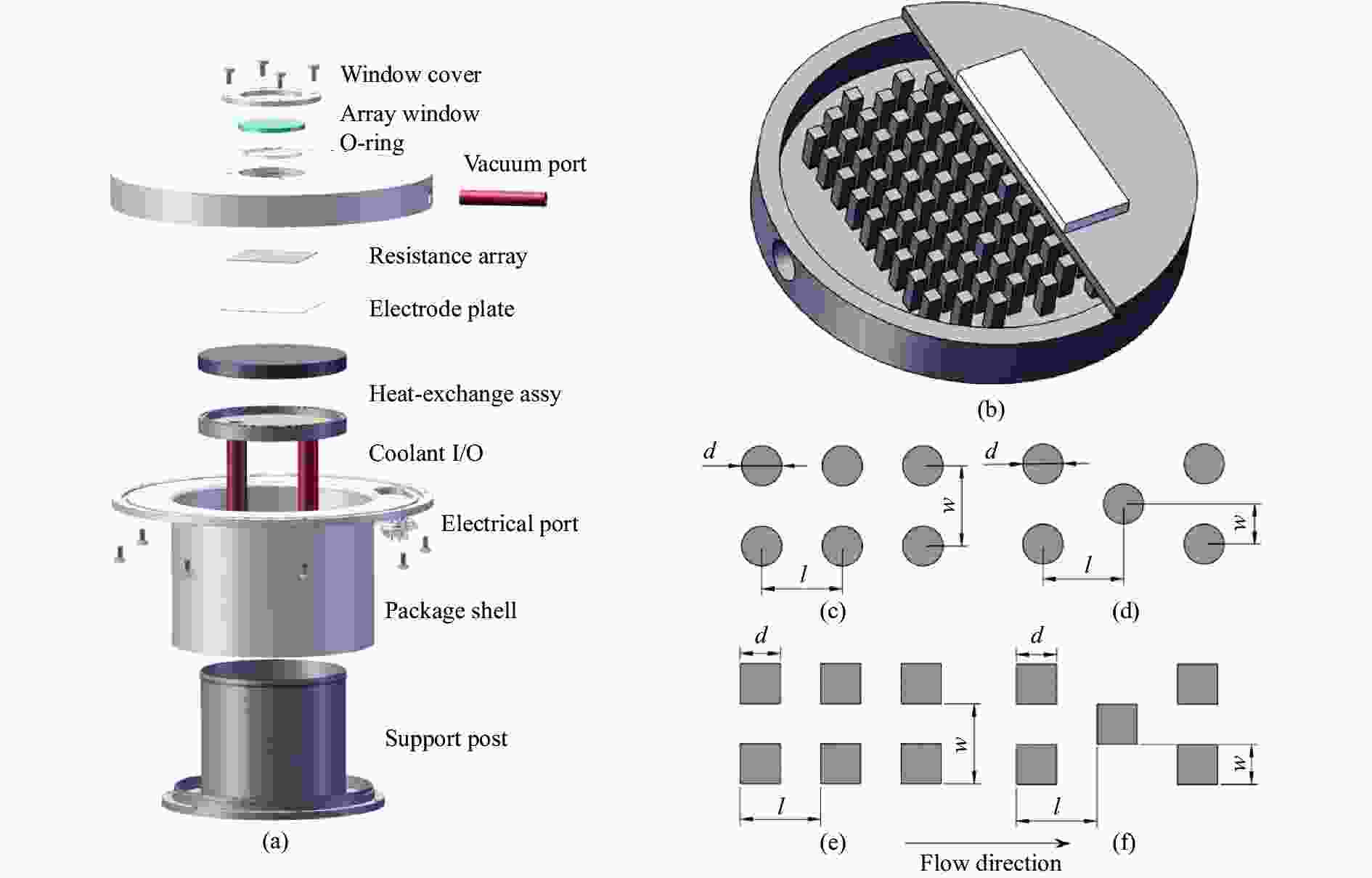
图 1 结构示意图。(a)封装结构;(b)液冷室结构;(c)~(f)扰流柱排布方式示意图
Figure 1. Schematic diagram of structure. (a) Package structure; (b) Liquid cooling chamber structure; (c)-(f) Diagram of arrangement of pin-fins
-
仿真分析时选用Fluent作为流体与热分析工具。两相流中气液界面与气体分布在热传导中起到了重要的作用,因此选取可以追踪气液界面的流体体积法(VOF)研究两相流的流动特性并分析不同结构液冷室的换热能力。在使用VOF进行多相流分析时,引入各流体的体积分数以完善流体的控制方程组。微元中混合流体的体积特性,例如密度和粘度,为各流体体积分数的加权平均值,且所有相共享共同的速度和温度场。热量和流体流动的物理过程可以用一组质量、动量和体积分数的方程来描述。对于不可压缩的牛顿流体,这些方程可以写成如下形式。
连续性方程:
$$ \frac{{\partial \rho }}{{\partial {\text{t}}}}{\text{ + }} \nabla( \rho {{{\boldsymbol{V}}} } ) = 0 $$ (1) 动量守恒方程:
$$ \begin{split} &\frac{{\partial (\rho {{{\boldsymbol{V}}} } ) }}{{\partial t}} + \nabla (\rho \mathbf{\mathit{{\boldsymbol{{\boldsymbol{V}}}}}} {{{\boldsymbol{V}}}}) = \\ &- \nabla p + \nabla (\mu (\nabla {{{\boldsymbol{V}}}} + \nabla {{{{\boldsymbol{V}}}}^{\rm{T}}})) + {F_s} \\ \end{split} $$ (2) 体积分数方程:
$$ \frac{{\partial \alpha }}{{\partial {\text{t}}}}{\text{ + }}{{{\boldsymbol{V}}} } \nabla \alpha = 0 $$ (3) 式中:V 为速度矢量;p 为压力;ρ 为密度;μ 为流体的动态粘度;Fs为界面附近的体积力,主要来源为气液界面的表面张力;α为液相或气相的体积分数。
-
为了简化计算,首先采用二维模型对液氮流动进行模拟,在优化的结构上进行两相流的三维仿真分析。文中采用RNG k-ε湍流模型,较之标准k-ε湍流模型,该模型在流动中存在涡流时能够提供更高旋涡流动的精度,对流线弯曲流动的仿真效果更好。RNG k-ε湍流模型为双方程涡粘模型,它将涡粘系数μT表示为湍动能k和湍流耗散率ε的函数,引入的关于湍动能k和湍流耗散率ε的微分方程如下式所示:
$$ \begin{split} &\frac{\partial }{{\partial {{t}}}}\left( {\rho k} \right){\text{ + }}\frac{\partial }{{\partial {{x}_{i}}}}\left( {\rho k{u_i}} \right)=\frac{\partial }{{\partial {x_j}}}\left( {{\alpha _k}{\mu _{eff}}\frac{{\partial k}}{{\partial {x_j}}}} \right) + \\ & {G_k} + {G_b}- \rho \varepsilon - {Y_M} + {S_k} \end{split} $$ (4) $$ \begin{split} &\frac{\partial }{{\partial {t}}}\left( {\rho \varepsilon } \right){\text{ + }}\frac{\partial }{{\partial {{x}_{i}}}}\left( {\rho \varepsilon {{u}_{i}}} \right){\text{ = }} \frac{\partial }{{\partial {{x}_{j}}}}\left( {{\alpha _\varepsilon }{\mu _{{eff}}}\frac{{\partial \varepsilon }}{{\partial {{x}_{j}}}}} \right){\text{ + }} \\ &{C_{1\varepsilon }}\frac{\varepsilon }{{k}}\left( {{G_{k}}{\text{ + }}{C_{3\varepsilon }}{G_{b}}} \right) - {C_{2\varepsilon }}\rho \frac{{{\varepsilon ^2}}}{{k}} - {R_\varepsilon }{\text{ + }}{S_\varepsilon } \end{split} $$ (5) 式中:C1ε=1.42;C2ε=1.68;Gk为平均速度梯度引起的湍流动能;Gb为由浮力产生的湍流动能;YM为可压缩湍流中波动膨胀对总耗散率的贡献;αk和αε分别为k和ε有效普朗特数的倒数;Sk和Sε为可定义的源项。
由于壁面处存在粘性层,为了较为准确地得出近壁面的流动状态,同时节省计算资源,使用半经验型的壁面函数计算壁面与充分发展的湍流区域之间的粘性影响区域。
为了对近壁面流动进行准确仿真,需要对流体模型近壁面处的网格进行细化,多使用y+作为近壁面网格划分的判据。对于文中的高雷诺数湍流模型,需要将第一层边界层厚度设定为y+处于对数率区间(20<y+<50),经多次迭代后,文中y+取值为30,对应的第一层边界层厚度为0.1 mm。确定第一层边界层厚度后,即可通过确定的柯朗数(Co)获得单次仿真的时间步长。柯朗数由下式定义:
$$ C{{o}} = \frac{{\Delta {{t}}}}{{\Delta {{x}}/{V_{{\text{fluid}}}}}} $$ (6) 式中:∆x 为第一层网格大小,即0.1 mm;Vfluid 是流体速度。
在当前的计算中设置了0.25的最大 Co 数,并使用基于0.25的固定Co数的可变时间步长来强制所有方程的时间步长相同,计算得出时间步长为2.5×10⁻⁵ s。仿真总时长设定为0.5 s,共进行20 000时间步长的计算。
在入口处,流体全部为液氮,温度为76.5 K,应用速度入口条件,为保证两相流拥有足够的冷却能力,流速设定为1 m/s。出口使用压力出口边界条件,压力设置为0 Pa。壁面采用非滑移边界条件。二维仿真模型中仅考虑不同结构对于流体流动的影响,因此不设外部热源,液冷室中流体全部为液氮。
三维仿真模型中需要考虑外部大功率热源对流体中相变与换热的影响。对于仿真中的相变,采取常用的Lee模型进行仿真。由于分析中主要考虑使用液氮-氮气两相流对大功率芯片进行散热,因此液体沸腾在相变中占据主导作用。
Lee模型用于计算相变时的相变率,当液体温度高于饱和温度时,即Tl>Tsat,液体气化,其相变率为:
$$ {\dot {\rm\mathit{m}}}_{\text{lv}}=coef f_{{\rm{eva}}}\times {\alpha }_{\text{l}}{\rho }_{\text{l}}\frac{({T}_{\text{l}}-{T}_{{\rm{sat}}})}{{T}_{{\rm{sat}}}} $$ (7) 式中:α为体积分数;ρ为密度;液氮-氮气的饱和温度为76.59 K;coeffeva
为蒸发频率;蒸发频率和液化频率设置在仿真软件中可以分别设置,考虑到沸腾换热时气化量远大于液化量,经多次迭代计算后,将蒸发频率设定为50,液化频率设置为0.1。 除拥有恒定热通量边界条件外,三维仿真模型的边界条件与二维一致。热边界条件设置如下。液冷室壁面与流体界面采用耦合方式连接,以仿真流体与固体中的换热现象。使用陶瓷加热片模拟电阻阵列芯片和陶瓷电极板组件,加热片通过环氧树脂胶结固定在钼质液冷室上,加热片的加热功率约为100 W,大小为30 mm×30 mm×2 mm。通过薄膜层模拟环氧树脂胶层的换热,薄膜层厚度为0.1 mm。以上仿真模型中涉及的材料参数如表1所示。
液冷室内流体的对流换热系数是衡量流体换热能力的主要指标。由于远离加热片的底面对换热贡献较小,因此后面分析时涉及的各结构对流换热系数为接近加热片的底面与侧面上的对流换热系数。对流换热系数的定义如公式(8)所示:
$$ h = \frac{q}{{{T_{{\rm{wall}}}} - {T_{{\rm{ref}}}}}} $$ (8) 式中:q为壁面处的热流密度;Twall为壁面温度;Tref为参考温度。
文中的液冷室结构较为复杂,因此将进出口流体平均温度作为参考温度。
表 1 仿真模型中涉及的材料物性参数表
Table 1. Material parameter used in the simulation model
Material ρ/kg·m−3 Cp/J·kg−1·K−1 λ/W·m−1·K−1 Liquid-N2 806 2041.5 0.14581 Gas-N2 1.138 1038 0.0242 Mo 10220 217 179 Ceramic 3960 126 449.8 Epoxy glue 1200 550 0.02 -
图2为空腔结构、微槽道结构和多扰流柱结构的液氮流速图,对于无微槽道或扰流柱的空腔结构,液氮未能形成较为均匀的速度分布,主流方向明显,换热区内流动不均匀,垂直主流方向上出现较大的涡流结构,见图2(a)。图2(b)是液冷室换热区域采用微槽道时液氮在液冷室内部的流速分布图。液氮在进入微槽道区域前速度分布较为均匀。但也可以看到,中心槽道附近流速较高,远离中心的槽道流速下降,使得中心区域换热效果较好,而边缘区域较差。

图 2 不同液冷室结构液氮流速图。 (a)空腔结构;(b)微槽道结构;(c)扰流柱结构
Figure 2. The velocity of liquid nitrogen in the different liquid cooling chamber. (a) Cavity structure; (b) Micro channel structure; (c) Pin-fins structure
图2(c)是液冷室换热区域采用多扰流柱结构时液氮在液冷室内部的流速分布图。扰流柱采用方形结构,扰流柱边长和间隔均为2 mm。与微槽道结构类似,方形扰流柱的存在使液氮在进入换热区域前速度分布较为均匀。与微槽道结构不同的是,低流速区集中于主流方向两侧,被扰流柱切割,且扰流柱结构换热面积最大,因此多扰流柱结构在三种结构中换热效果最好。
三维仿真结果表明,以上三种结构的对流换热系数分别为1870 W/(m2·K)、3266 W/(m2·K)和3364 W/(m2·K),微槽道和多扰流柱结构的对流换热系数较空腔结构分别提升74.65%和79.89%,换热能力大大提高,与上述流速分析结论相符。
-
图3为扰流柱形状和排布对液氮流速的影响。平行排布的多扰流柱结构中,主流方向为流体入口至出口方向。与方形扰流柱相比,在液氮进入热交换区后,同时出现与主流方向基本呈45°角的支流,见图4(a)。将液冷室扰流柱的排列方式由平行排布改为交错排布,进一步强化45°角方向的流动,与平行排布的扰流柱相比,无论是圆形结构还是方形结构,主流影响减弱,出现沿交错排布方向的众多支流,见图3(b)、图3(c)。比较交错排布的两种扰流柱结构发现,方形扰流柱结构流速在整个区域分布更均匀。

图 3 扰流柱形状和排布对液氮流速的影响。 (a)圆形扰流柱平行排布;(b)圆形扰流柱交错排布;(c)方形扰流柱交错排布
Figure 3. Flow velocity diagram of liquid nitrogen flow in a liquid cooling chamber with different shapes and arrangements. (a) Circular inline pin-fins; (b) Circular staggered pin-fins; (c) Square staggered pin-fins

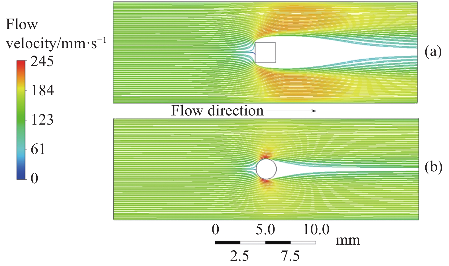
图 4 单个扰流柱结构中液氮流线分布图(Re=8400)。(a)方形扰流柱;(b)圆形扰流柱
Figure 4. Distribution of streamlines in a single pin-fin structure (Re=8400). (a) Square pin-fin; (b) Circular pin-fin
为了进一步确认扰流柱形状和排布的影响,分析了相同雷诺数情况下单个圆形和方形扰流柱对液氮流速分布的影响,如图4所示。在主流方向上,流体在经过扰流柱时因管径缩小,产生了显著的加速。流体在流经方形扰流柱时被垂直于主流方向的壁面阻挡,转而向两侧发展,在与原始流向呈30°~60°的较大范围内的会出现高流速区,见图4(a)。而流体在经过圆形扰流柱后加速区域较集中,主要是在与原始流向呈45°方向小范围区域,见图4(b)。另外,如果扰流柱交错排列,较高流速区的液氮又会受下一个扰流柱阻挡而进一步分流,从而更有利于流速的均匀分布。
-
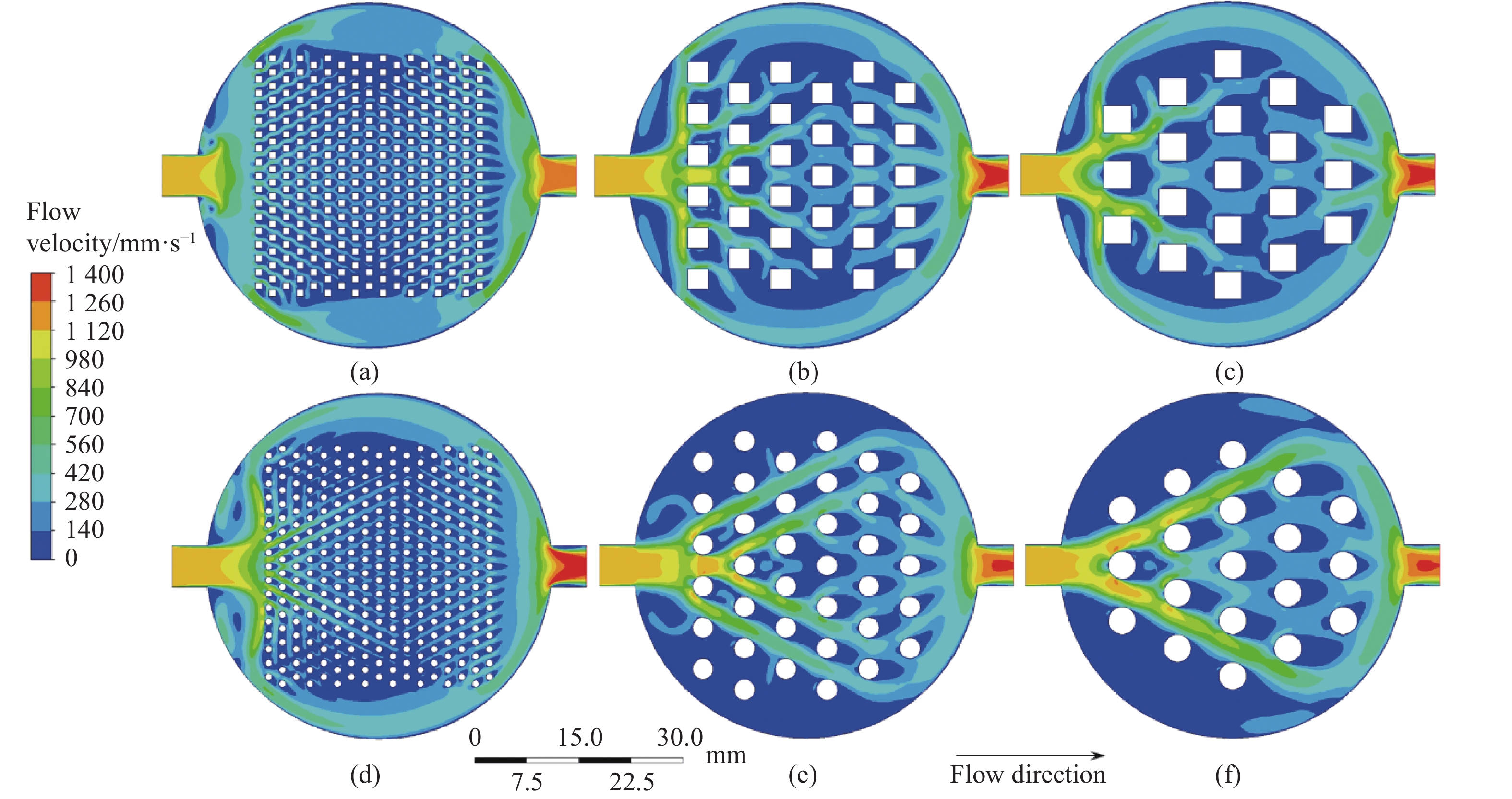
图5为不同尺寸扰流柱的流速对比图。圆形扰流柱在尺寸为1.0 mm时,由于扰流柱阵列流阻较大,液冷室边缘的流体流速较快;尺寸大于2.0 mm后,流体主要流经扰流柱阵列,并在液冷室边缘形成集中连片的低流速区,随着扰流柱尺寸的增大,低流速区面积也不断增大。方形扰流柱换热区域流阻较大,因此在1.0~4.0 mm尺寸范围内液冷室边缘的液氮流速均较快,在换热区域中,扰流柱后方形成的低流速区随着扰流柱尺寸的增加面积增大。因此,无论是圆形扰流柱还是方形扰流柱,尺寸超过4.0 mm均不利于流体换热,因此下面在对流换热系数分析中仅考虑1.0~3.0 mm尺寸的不同结构。

图 5 不同尺寸交错排布扰流柱液冷室中的液氮流速图。 (a)方形扰流柱1.0 mm;(b)方形扰流柱3.0 mm;(c)方形扰流柱4.0 mm;(d)圆形扰流柱1.0 mm;(e)圆形扰流柱3.0 mm;(f)圆形扰流柱4.0 mm
Figure 5. Flow velocity diagram of liquid nitrogen in a liquid cooling chamber with staggered arrangement of different size pin-fins. (a) Square, 1.0 mm; (b) Square, 3.0 mm; (c) Square, 4.0 mm; (d) Circular, 1.0 mm; (e) Circular, 3.0 mm; (f) Circular, 4.0 mm
-
图6是不同形状、大小和排布方式扰流柱结构液冷室的对流换热系数图。总的来说,交错排布的扰流柱结构换热能力优于平行排布,方形扰流柱换热能力优于圆形扰流柱。平行排布扰流柱结构的对流换热系数随扰流柱尺寸增加而降低。交错排布的结构中,2 mm的方形扰流柱换热效果最好,圆形扰流柱尺寸为1~2 mm时对流换热系数相近,尺寸增加后对流换热系数降低。2 mm方形扰流柱结构对流换热系数最高,为4223 W/(m2·K),较空腔结果提高125.83%。

图 6 不同扰流柱结构中对流换热系数分布图
Figure 6. Distribution diagram of convective heat transfer coefficient in pin-fins structure with different shapes, sizes, and arrangements
造成上述对流换热系数差异的原因如下。首先,交错排布时流体在液冷室中的流动范围更广,因此交错排布的扰流柱结构换热能力由于平行排布。方形扰流柱由于壁面阻挡效应,液冷室中的流体易形成多支流流动模式,较圆形扰流柱更有利于换热的进行。过小的扰流柱尺寸使得换热区流阻过大,缺少流体进行换热;较大的扰流柱则为造成液冷室中低流速区域聚集,恶化液冷室换热能力。因此,交错排布的2 mm方形扰流柱结构最有利于换热。
-
根据对流换热系数的分析结果,选取2 mm方形交错排布的扰流柱结构进行验证,开展三维温度仿真,并加工了该结构的液冷室进行测试。图7(a)是三维仿真结果的流线图,可以看出流线在进入液冷室后能够较为均匀地分配到换热区域中,包括液冷室边缘,在换热区域中,交错分布的扰流柱起到了较好的分流作用。在扰流柱后方,存在几乎无流线分布的低流速区,这些区域中流体流速慢,对大功率芯片进行散热时此处的流体易相变产生气膜,不利于散热,该结果与二维流速分布较为吻合。加热芯片尺寸为30 mm×30 mm×2 mm,加热功率107.6 W,实测了冷头周边区域A、B、C三点温度分别为79.2、77.1、78.6 K,而相同加热功率的仿真结果如图7(b)所示,A、B、C三点的温度分别为78.5、76.7、78.0 K,比实测结果略低,差值为0.4~0.7 K。主要是测温点胶结界面热阻引起,实验中Pt100导线直径为0.3 mm,在室温端取293 K时计算漏热为0.06 W,每个Pt100测温电阻面积约为2 mm×2 mm,因此通过胶接面的热通量q为7.51×10³ W/m2。根据参考文献[26],考虑胶结界面热阻值为4.865×10−5 m2·K/W,代入热通量q计算后,可以得出胶接面温差约为0.37 K,该温差与仿真-验证实验的0.4~0.7 K温差相近。
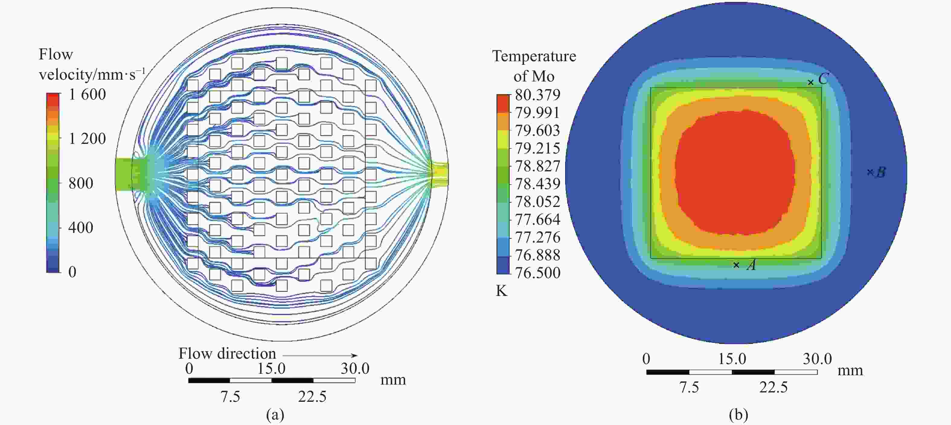
图 7 增强换热结构液冷室中流线与温度分布图。 (a) 流线分布图;(b) 温度分布图
Figure 7. Streamline and temperature distribution diagram in the liquid cooling chamber with the enhanced heat exchange structure. (a) Streamline distribution diagram; (b) Temperature distribution diagram
-
(1) 运用CFD方法对比了空腔结构、微槽道结构和扰流柱结构三种液冷室的流速分布,扰流柱结构最优。扰流柱的形状和排列方式对流速分布有较大影响,圆形扰流柱易发展45°方向支流,方形扰流柱结构有利于垂直方向流速均匀化,扰流柱的交错排布较有利于发展多支流形式,提高平均流速,有利于散热。
(2) 扰流柱交错排列时,对于不同尺寸的扰流柱结构,在尺寸为2 mm时,对流换热系数存在高点。交错排布的结构中,2 mm的方形扰流柱换热效果最好,该结构的对流换热系数为4223 W/(m2·K),较空腔结构提高125.83%。
(3) 设计了测试验证结构,当加热功率107.6 W时,冷头测温点温度与仿真结果有较好的对应性,选定的测温点误差约为0.4~0.7 K,误差主要来源于验证实验时DW-3胶接面上的界面热阻。
Flow and heat analysis of liquid nitrogen cooling structure by CFD method
-
摘要: 低温应用的大功率器件需要设计高冷却效率的液冷室结构。采用计算流体动力学(CFD)方法模拟了以液氮-氮气两相流为制冷剂的空腔结构、微通道结构和扰流柱结构的流动与传热过程。结果表明,相比于空腔结构和微槽道结构,扰流柱结构具有较好的换热能力。圆形扰流柱易发展45°方向支流,而方形扰流柱结构有利于垂直方向流速均匀化。相较于平行排布,扰流柱交错排列时圆形和方形扰流柱结构中流速分布更为均匀。对比对流换热系数发现,交错排布优于平行排布,方形扰流柱优于圆形扰流柱。换热效果最好的结构为交错排布的2 mm方形扰流柱,对流换热系数为4223 W/(m2·K),较空腔结构提高125.83%。采用上述结构进行测试验证,在107.6 W加热功率工况下冷头测温点温度与相同功率下仿真结果有较好的对应性。Abstract: High-power devices for low-temperature applications require a liquid-cooled chamber structure with high cooling efficiency. The Computational Fluid Dynamics (CFD) method was used to simulate the flow and heat transfer process of the cavity structure, the microchannel structure, and the pin-fins structure under the condition of the liquid nitrogen-nitrogen two-phase flow as the refrigerant. The results show that the pin-fins structure has the best heat exchange effect among the three above structures. The circular pin-fins structure is easy to develop a branch in the direction of 45°, and the square pin-fins structure is conducive to the uniform flow velocity in the vertical direction. Compared with the parallel pin-fins structure, the flow velocity distribution in the circular and square pin-fins is more uniform when the pin-fins are staggered. Comparing the convective heat transfer coefficients in different liquid cooling chambers with pin-fin structures, under the same other parameters, the staggered arrangement is better than the parallel arrangement, and the square pin-fin is better than the circular pin-fin. The structure with the best heat transfer effect is the staggered 2 mm square pin-fin structure, and the convective heat transfer coefficient is 4223 W/(m2·K), which is 125.83% higher than cavity structure. The above structure is manufactured for physical verification. The temperature of the cold head under the 107.6 W heating power corresponds well with the simulation result under the same condition.
-
Key words:
- high-power devices /
- pin-fin /
- two-phase flow /
- convective heat transfer coefficient
-
图 1 结构示意图。(a)封装结构;(b)液冷室结构;(c)~(f)扰流柱排布方式示意图
Figure 1. Schematic diagram of structure. (a) Package structure; (b) Liquid cooling chamber structure; (c)-(f) Diagram of arrangement of pin-fins
图 2 不同液冷室结构液氮流速图。 (a)空腔结构;(b)微槽道结构;(c)扰流柱结构
Figure 2. The velocity of liquid nitrogen in the different liquid cooling chamber. (a) Cavity structure; (b) Micro channel structure; (c) Pin-fins structure
图 3 扰流柱形状和排布对液氮流速的影响。 (a)圆形扰流柱平行排布;(b)圆形扰流柱交错排布;(c)方形扰流柱交错排布
Figure 3. Flow velocity diagram of liquid nitrogen flow in a liquid cooling chamber with different shapes and arrangements. (a) Circular inline pin-fins; (b) Circular staggered pin-fins; (c) Square staggered pin-fins
图 4 单个扰流柱结构中液氮流线分布图(Re=8400)。(a)方形扰流柱;(b)圆形扰流柱
Figure 4. Distribution of streamlines in a single pin-fin structure (Re=8400). (a) Square pin-fin; (b) Circular pin-fin
图 5 不同尺寸交错排布扰流柱液冷室中的液氮流速图。 (a)方形扰流柱1.0 mm;(b)方形扰流柱3.0 mm;(c)方形扰流柱4.0 mm;(d)圆形扰流柱1.0 mm;(e)圆形扰流柱3.0 mm;(f)圆形扰流柱4.0 mm
Figure 5. Flow velocity diagram of liquid nitrogen in a liquid cooling chamber with staggered arrangement of different size pin-fins. (a) Square, 1.0 mm; (b) Square, 3.0 mm; (c) Square, 4.0 mm; (d) Circular, 1.0 mm; (e) Circular, 3.0 mm; (f) Circular, 4.0 mm
图 6 不同扰流柱结构中对流换热系数分布图
Figure 6. Distribution diagram of convective heat transfer coefficient in pin-fins structure with different shapes, sizes, and arrangements
图 7 增强换热结构液冷室中流线与温度分布图。 (a) 流线分布图;(b) 温度分布图
Figure 7. Streamline and temperature distribution diagram in the liquid cooling chamber with the enhanced heat exchange structure. (a) Streamline distribution diagram; (b) Temperature distribution diagram
表 1 仿真模型中涉及的材料物性参数表
Table 1. Material parameter used in the simulation model
Material ρ/kg·m−3 Cp/J·kg−1·K−1 λ/W·m−1·K−1 Liquid-N2 806 2041.5 0.14581 Gas-N2 1.138 1038 0.0242 Mo 10220 217 179 Ceramic 3960 126 449.8 Epoxy glue 1200 550 0.02  下载: 导出CSV
-
[1] James J, Bryant P, Solomon S, et al. OASIS: Cryogenically-optimized resistive Arrays & IRSP subsystems for space-background IR simulation[C]//Technologies for Synthetic Environments: Hardware-in the-Loop Testing XI. Bellingham: SPIE-Int Soc Optical Engineering, 2006: 20812. [2] McHugh S, Franks G, LaVeigne J. High-temperature MIRAGE XL (LFRA) IRSP system development[C]//Infrared Imaging Systems: Design, Analysis, Modeling, and Testing XXVIII. Bellingham: SPIE-Int Soc Optical Engineering, 2017: 10178. [3] Karayiannis T G, Mahmoud M M. Flow boiling in microchannels: Fundamentals and applications [J]. Applied Thermal Engineering, 2017, 115: 1372-1397. doi: 10.1016/j.applthermaleng.2016.08.063 [4] Back D, Drummond K P, Sinanis M D, et al. Design, fabrication, and characterization of a compact hierarchical manifold microchannel heat sink array for two-phase cooling [J]. IEEE Transactions on Components Packaging and Manufacturing Technology, 2019, 9: 1291-1300. doi: 10.1109/TCPMT.2019.2899648 [5] Smakulski P, Pietrowicz S. A review of the capabilities of high heat flux removal by porous materials, microchannels and spray cooling techniques [J]. Applied Thermal Engineering, 2016, 104: 636-646. doi: 10.1016/j.applthermaleng.2016.05.096 [6] Wu Z Y, Zhang W, Sun Z Y, et al. Research progress on the flow boiling heat transfer enhancement in the microchannel [J]. Micronanoelectronic Technology, 2019, 56(2): 126-132. [7] Kuznetsov V V. Fundamental issues related to flow boiling and two-phase flow patterns in microchannels-experimental challenges and opportunities [J]. Heat Transfer Engineering, 2019, 40(9-10): 711-724. doi: 10.1080/01457632.2018.1442291 [8] Leena R, Syamkumar G, Prakash M J. Experimental and numerical analyses of multiple jets impingement cooling for high-power electronics [J]. IEEE Transactions on Components Packaging and Manufacturing Technology, 2018, 8: 210-215. doi: 10.1109/TCPMT.2017.2783629 [9] Wang Jixiang, Li Yunze, Li Jiaxin, et al. A gas-atomized spray cooling system integrated with an ejector loop: Ejector modeling and thermal performance analysis. [J]. Energy Conversion and Management, 2019, 180: 106-118. doi: 10.1016/j.enconman.2018.10.095 [10] Zhang T, Yan K F, Zhang C, et al. Effects of pin-finned array and porous surface on two-phase confined jet-impingement cooling [J]. Chemical Industry and Engineering Progress, 2019, 38(10): 4470-4480. (in Chinese) [11] Izadi A, Siavashi M, Xiong Qingang. Impingement jet hydrogen, air and Cu-H2O nanofluid cooling of a hot surface covered by porous media with non-uniform input jet velocity [J]. International Journal of Hydrogen Energy, 2019, 44: 15933-15948. doi: 10.1016/j.ijhydene.2018.12.176 [12] Majhool A A A K, Jasim N M. Prediction of the initial drop size and velocity distribution in the cold cryogenic spray [J]. International Journal of Heat and Technology, 2020, 38(3): 629-640. doi: 10.18280/ijht.380307 [13] Lee J, Mudawar I. Low-temperature two-phase microchannel cooling for High-Heat-Flux thermal management of defense electronics [J]. IEEE Transactions on Components and Packaging Technologies, 2009, 32(2): 453-465. doi: 10.1109/TCAPT.2008.2005783 [14] Zhang T, Wang S Y, Rui J C, et al. Characteristic of an Ω-shape microchannel heatsink with different working fluid [J]. Chemical Industry and Engineering Progress, 2018, 37(8): 2954-2961. (in Chinese) [15] Xia G D, Lv Y Z, Cheng L X, et al. Experimental study and dynamic simulation of the continuous two-phase instable boiling in multiple parallel microchannels [J]. International Journal of Heat and Mass Transfer, 2019, 138: 961-984. doi: 10.1016/j.ijheatmasstransfer.2019.04.124 [16] Wang C L, Tian M C. Experimental research on low Reynolds number liquid-liquid two-phase flow and heat transfer characteristics in micro channels [J]. CIESC Journal, 2021, 72(3): 1322-1332. [17] Liu Z Y, Yao X Y, Cheng X, et al. Experimental study on two-phase boiling in wavy copper microchannels fabricated with ultrafast laser micromachining [J]. Journal of Micromechanics and Microengineering, 2020, 30(6): 065011. doi: 10.1088/1361-6439/ab870b [18] Rasouli E, Naderi C, Narayanan V. Pitch and aspect ratio effects on single-phase heat transfer through microscale pin fin heat sinks [J]. International Journal of Heat and Mass Transfer, 2018, 118: 416-428. doi: 10.1016/j.ijheatmasstransfer.2017.10.105 [19] Rasouli E, Narayanan V. Single-phase cryogenic flow and heat transfer through microscale pin fin heat sinks [J]. Heat Transfer Engineering, 2016, 37(11): 994-1011. doi: 10.1080/01457632.2015.1098271 [20] Singh N R, Onkar S, Ramkumar J. Thermo-hydraulic performance of square micro pin fins under forced convection [J]. International Journal of Heat and Technology, 2021, 39(1): 170-178. doi: 10.18280/ijht.390118 [21] Saravanan V, Umesh C K, Seetharamu D H K. Numerical investigation of pressure drop and heat transfer in pin fin heat sink and micro channel pin fin heat sink [J]. International Journal of Heat and Technology, 2018, 36(1): 267-276. doi: 10.18280/ijht.360136 [22] Pati B, Sharma B, Palo A, et al. Numerical investigation of pin-fin thermal performance for staggered and inline arrays at low Reynolds number [J]. International Journal of Heat and Technology, 2018, 36(2): 697-703. doi: 10.18280/ijht.360235 [23] Zhao Y X, Lai Z C, Hu H T. Flow boiling heat transfer and pressure drop characteristics of R1234 ze(E) in metal foam filled tubes [J]. CIESC Journal, 2021, 72(10): 5074-5081. [24] Ning J H, Sun Z Y, Bao C X, et al. Theoretical analysis on the cooling performance of high heat flux chip with dry ice [J]. CIESC Journal, 2021, 72(4): 2047-2056. [25] Liang X, Cai D H, Deng J J, et al. Characteristics of boiling heat transfer and pressure drop of R410 A in 5 mm diameter inner-grooved copper tubes [J]. Journal of Huazhong University of Science and Technology (Natural Science Edition), 2019, 47(3): 1-6. (in Chinese) [26] Wang Z. Research on thermal interface resistance of cryogenic packaging for infrared focal plane assembly[D]. Shanghai: University of Chinese Academy of Sciences (Shanghai Institute of Technical Physics, Chinese Academy of Sciences), 2020. -

 点击查看大图

计量
- 文章访问数: 307
- HTML全文浏览量: 98
- PDF下载量: 76
- 被引次数: 0


