


-
大口径太阳望远镜系统在运行过程中受太阳辐射导致的光机结构变形、不同指向重力弯沉、风载光机结构变形、环境温度变化等因素影响,产生波前像差,导致太阳望远镜系统成像质量显著下降,制约太阳大气成像分辨率。这些像差按来源分类为静态位置失配波前像差、准静态位置失配波前像差和非失配波前像差,其像差形式以低阶像差为主,时间频率上以低时间频率像差为主。
在两镜系统中,一般以主镜为基准,通过调整次镜刚体位置补偿由于装配或等效装配关系改变引起的波前像差。文献分析结果表明[1-3],次镜沿光轴方向的平移可以按比例补偿离焦和球差,次镜沿垂直于光轴方向的平移和倾斜可以按比例补偿倾斜、彗差、像散。建立系统波前像差与次镜刚体位置关系后,通过六自由度平台对次镜刚体位置进行调整,实现对低阶像差的校正。次镜刚体位移校正波前像差一般用于光学望远镜观测前的静态装调,尚未发现用于观测过程中的位置失配、非失配波前像差校正的文献报道。
常见的计算机辅助装调方法有矢量波像差法、评价函数退化法、人工神经网络法和灵敏度矩阵法。鞠国浩[4]等将矢量波像差法应用于离轴三反望远镜单个侧向离心量的计算,得到计算离心量误差值小于2.2%的结果;郭攀[5]等使用矢量波像差法对两反系统装调,得到轴上视场像差均方根(Root Mean Square, RMS)值为0.112λ的装调效果,矢量像差法对面型误差和元件失调均有较高的计算能力,但是在实际像差校正场景下受限于构建模型参数的精确性,且需要多视场的检测;刘波等[6]使用评价函数退化法对R-C系统进行精装调,得到系统轴上视场像差RMS为0.078λ的装调结果,评价函数退化法将系统实测波像差代入光学设计软件中计算元件的失调量,计算精度依赖于光学设计软件中的算法,精确度较低;左晓舟[7]等使用人工神经网络法对两镜系统进行装调,得到轴上视场像差优于λ/16的结果;王钰等[8]将人工神经网络法运用于三镜系统的失调量解算,得到失调量均方根误差小于7.04%的结果。人工神经网络法较好地解决了系统像差与失调量的非线性关系,但受到训练样本以及网络结构优劣的影响,需要找到样本数量和神经网络复杂程度的最优配置才能使计算结果更为精确;灵敏度矩阵法是目前应用最广泛的装调方法,传统的灵敏度矩阵法是一阶线性模型[9-11],当元件失调量较大时拟合效果较差,中国科学院长春光学精密机械与物理研究所的顾志远将灵敏度矩阵扩展到二阶[12],较好地解决了系统波像差与元件失调量关系非线性的问题,并运用于离轴望远镜的装调,得到全视场波前像差RMS小于0.1λ的效果;中国科学院光电技术研究所的曹宇泽[13]使用二阶灵敏度矩阵法对卡塞格林系统进行仿真调整,得到全视场波前像差RMS均小于0.03λ的结果。上述装调方法均有各自的优缺点,其中二阶灵敏度矩阵法以数学模型简单、所需样本数量少、计算精度高被广泛应用[14],但其尚未用于望远镜运行过程中的位置失配及非失配波前像差的校正。
基于以上背景,文中提出对太阳望远镜的波前探测数据进行时空分频,分解出由次镜刚体校正的低时空频率像差成分,根据次镜刚体位移量与系统像差变化量的关系以及次镜刚体调整机构的行程能力计算次镜刚体校正量,在不增加光学系统复杂度的前提下实现对望远镜系统运行过程中由于静态位置失配误差、风载弯沉等准静态位置失配误差以及热变形等非失配误差引起低时空频率像差的实时校正,提升太阳望远镜成像分辨力,并通过数值仿真和实验验证的方法对60 cm POST (Prototype for the Chinese Large Solar Telescop)太阳望远镜系统进行不同来源像差的校正研究,结果表明,次镜刚体位移对位置失配误差、非失配误差和多源混合误差引起波前像差均能进行有效校正。
-
太阳望远镜在实际观测过程中的波前像差按其来源具体可分为三种类型:第一类为光学装调误差引起的静态位置失配波前像差,此类像差大多来源于主次镜位置失调;第二类为太阳辐射结构变形、指向相关结构弯沉、风载结构变形等引起的准静态位置失配波前像差,此类像差形式与静态位置失配波前像差相同,可以等效为主次镜位置失调所产生像差;第三类为低频加工误差、镜面热变形、环境温度变化等引起的非失配波前像差,此类像差往往表现为任意大小的像差组合。上述因素引起的波前像差主要以低阶像差(如倾斜、离焦、像散、彗差、球差)为主,且其时间频率较低,对于这些低阶低频的像差,将其定义为望远镜运行过程中的低时空频率像差。
夏克-哈特曼波前探测器能够实现对太阳望远镜运行过程中波前像差的实时探测,当太阳望远镜处于静态状态下时,太阳望远镜次镜的空间位置Х与夏克-哈特曼波前探测器的波前探测数据Ф存在如下关系:
$$ \varPhi = {{F}}(X) $$ (1) 太阳望远镜的次镜共有六个自由度的位移量,分别为X轴平移量Dx、Y轴平移量Dy、Z轴平移量Dz以及绕X轴旋转量Tx、绕Y轴旋转量Ty、绕Z轴旋转量Tz。由于次镜关于Z轴旋转对称,绕Z轴旋转量Tz不会对波前探测数据产生影响,故次镜共有五个方向上的位移对夏克-哈特曼波前探测器的波前探测数据Ф产生影响。利用次镜刚体位移对波前探测数据产生影响,实质上是影响系统像差的这一特性,可以达到使用次镜刚体位移对太阳望远镜系统像差进行校正的目的。
将望远镜次镜在某单一自由度方向上进行位移,如Tx,分别测量其在−0.05°、−0.04°、···、+0.05°处的夏克-哈特曼波前数据Ф,并分解为各项Zernike系数,文中采用的Zernike多项式的波前图样如图1所示,其中,Z1项为活塞像差,Z2项、Z3项分别为X和Y方向上的倾斜像差,Z4项为离焦像差,Z5项、Z6项分别为45°和0°像散,Z7项、Z8项分别为X方向和Y方向上的彗差,Z9项为球差。在五个自由度方向上均进行此操作,并代入灵敏度矩阵中进行拟合,得到次镜位移量与Zernike系数的数学关系如下:
$$ Z - {Z_0} = A\Delta {{X}}{.^2} + B\Delta {{X}} + \delta $$ (2) 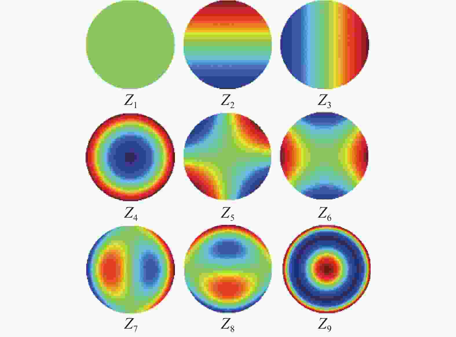
图 1 Zernike多项式与其波前图样
Figure 1. Zernike polynomials and their wavefront patterns
式中:$ Z $为当前位置处的Zernike系数;$ {Z_0} $为起始位置处的Zernike系数;$ A $、$ B $分别为二次项系数矩阵和一次项系数矩阵;$\Delta {{X}}$表示次镜沿每个自由度方向上的位移量;$ \delta $为残差余项;$\Delta {{X}}{.^2}$表示次镜每个自由度方向上位移量的平方所形成的矩阵,如公式(3)所示:
$$ \Delta {{X}}{.^2} = [\begin{array}{*{20}{c}} {\Delta D{x^2}}&{\Delta D{{{y}}^2}}&{\Delta D{{\textit{z}}^2}}&{\Delta T{x^2}}&{\Delta T{y^2}} \end{array}]' $$ (3) 在望远镜实际运行中,对系统像差的校正转化为求解使得轴上视场像差的Zernike系数Z取最小值的次镜位移量,文中采用最小二乘法的方式进行求解。根据次镜位移量由位姿调整机构对次镜的位姿进行实时调整,最终实现对望远镜实际运行中低时空频率像差的实时闭环校正。
-
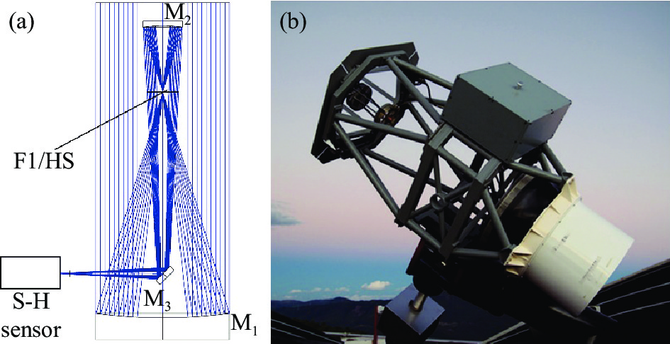
格里高利系统是常见的太阳望远镜形式,文中对POST太阳望远镜系统[15-17]进行次镜刚体位移校正的数值仿真研究,望远镜光学布局和装置图如图2所示,系统参数如表1所示。
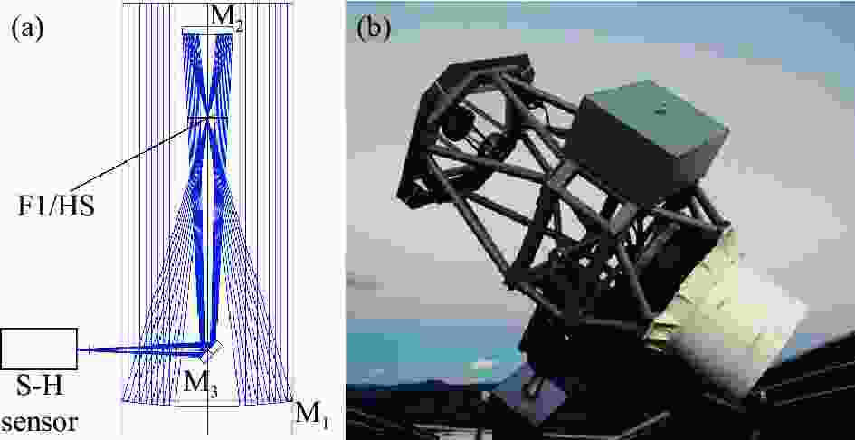
表 1 望远镜参数
Table 1. Telescope parameters
Surface Mechanical diameter d/mm Radius of curvature r/mm Interval D/mm Conic factor Primary mirror 600 −2 040 −1320 −1 Secondary mirror 180 504.812 - −0.466 为建立Zernike系数与次镜位置变化量的数学关系,保证系统像差次镜校正量的精确计算,对次镜进行五个自由度方向上的位置扰动,每个自由度方向上等间距选取11个采样点,受次镜位置影响的像差与次镜位置变化量的关系如图3所示。
分析可得,Dx和Ty对系统像差中的Z2项、Z8项有着相同程度的影响,但是其对Z4项、Z6项的影响不同,因此当系统像差中的Z2项、Z8项需要校正时,需要同时对Dx、Ty进行调整,在保证减小Z2项、Z8项的同时尽可能降低Z4项、Z6项。Dy和Tx对系统像差中Z3项、Z7项、Z4项、Z6项的校正,Dz对系统像差中Z4、Z9项的校正也遵循以上原则。通过对次镜在Dx、Dy、Dz、Tx、Ty五个自由度方向上的位置调整,达到最小化系统像差的目的。
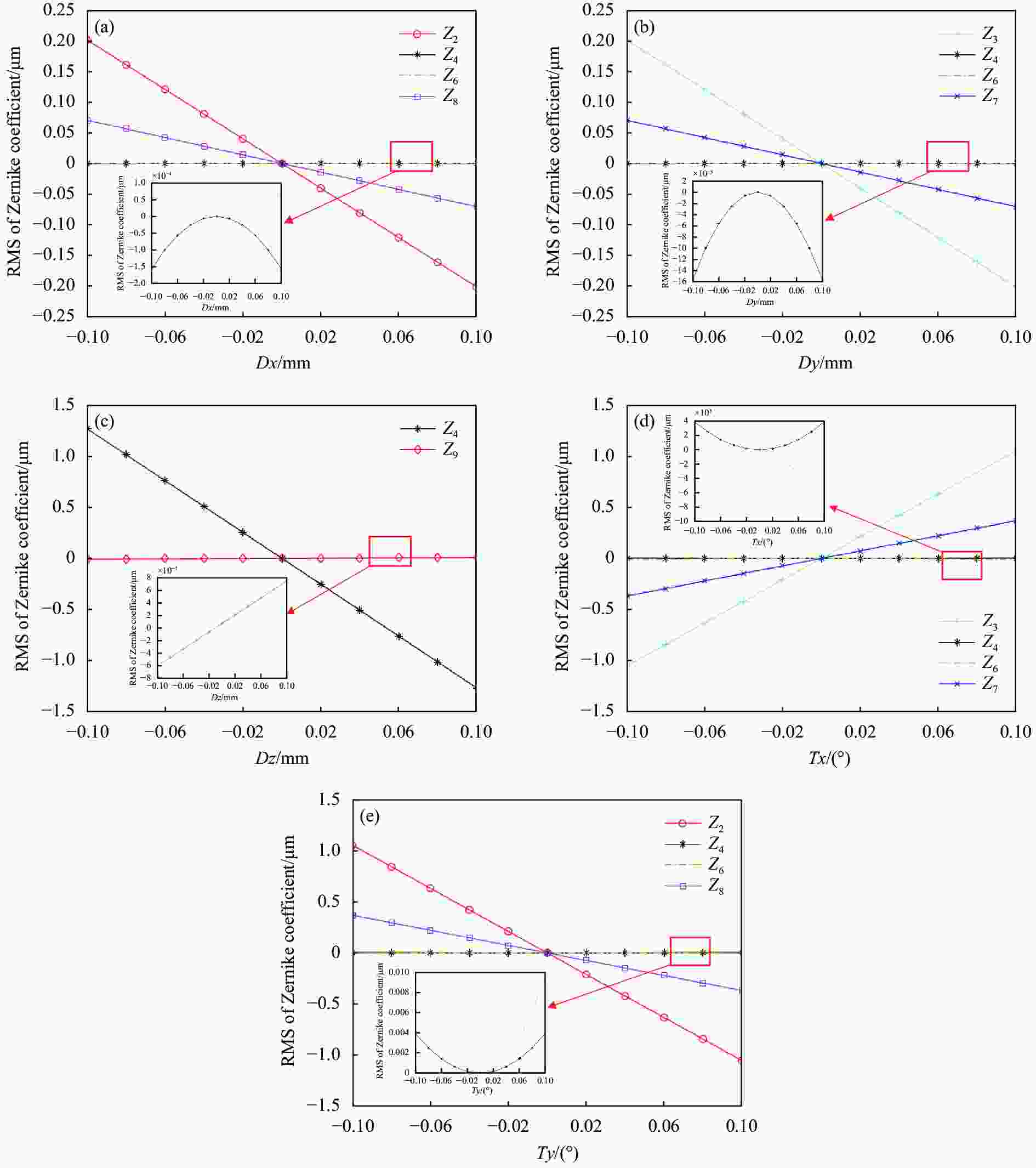
图 3 Zernike系数受次镜五个自由度方向位移影响曲线图。 (a) x方向平移;(b) y方向平移;(c) z方向平移;(d) x方向旋转;(e) y方向旋转
Figure 3. Curve of Zernike coefficients affected by the displacement in the direction of five degrees of freedom of secondary mirror. (a) Translation around x axis; (b) Translation around y axis; (c) Translation around z axis; (d) Rotation around x axis; (e) Rotation around y axis
-
通过引入不同类型的像差,能够验证由建立起数学关系计算得到的次镜位移量对系统像差的校正能力。由指向相关结构弯沉、风载结构变形、太阳辐射结构变形等准静态位置失配误差引起的像差与静态位置失配像差形式相同,以倾斜、离焦、彗差为主,同时含有少量像散与球差。
位置失配误差引起像差的次镜刚体校正效果如图4所示,使用次镜刚体校正后,系统像差RMS值由1.331 μm降低至0.005 μm,次镜刚体位移校正效果良好,位置失配误差引起像差被完全校正。
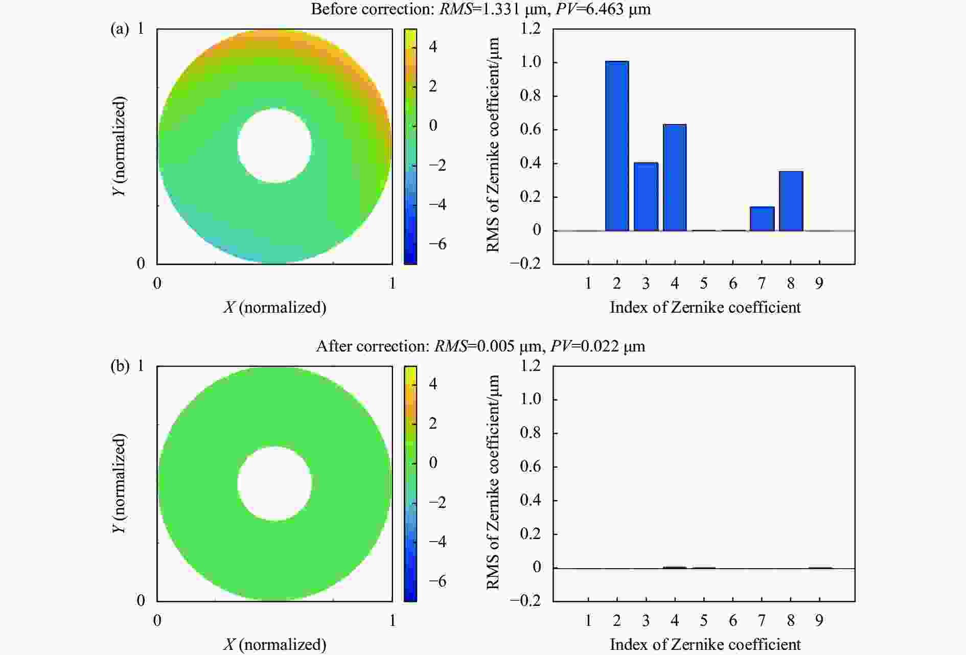
图 4 位置失配误差引起像差的波前图和Zernike系数。 (a) 校正前; (b) 校正后
Figure 4. Wavefront diagram and Zernike coefficients of aberration caused by position mismatch error. (a) Before correction; (b) After correction
-
对于镜面热变形、环境温度变化、低频加工误差等因素引入的非失配误差,其具有低阶像差大小以任意比例组合的特点,与主次镜间位置失配引起的像差组合比例具有显著区别,但是从形式上看,依然以倾斜、离焦、彗差、像散、球差为主。对非失配误差进行反演与补偿的研究,次镜刚体位移校正结果如图5所示。
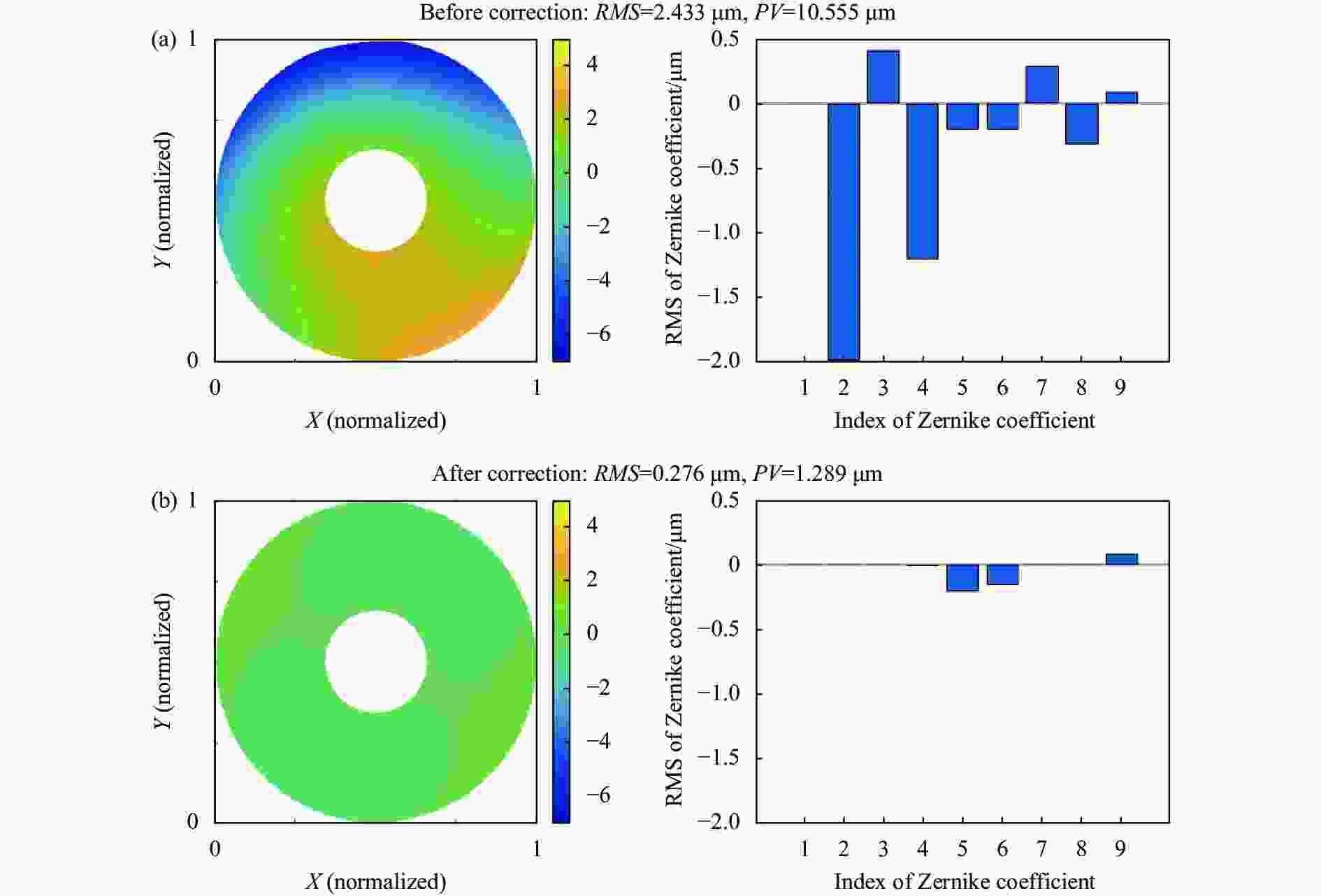
图 5 非失配误差引起像差的波前图和Zernike系数。(a) 校正前; (b) 校正后
Figure 5. Wavefront diagram and Zernike coefficients of aberration caused by non-mismatch error. (a) Before correction; (b) After correction
分析波前数据,波前像差RMS值由2.433 μm降低至0.276 μm,其中倾斜、离焦、彗差项被完全校正,Z6项0°像散由−0.197 μm降低至−0.150 μm,剩余像差以Z9项球差、Z6项0°像散为主(次镜对Z5项无校正能力),对其继续校正会产生更大量的倾斜、彗差、离焦,不满足整体像差RMS最小化的条件。据此可以得出结论,对于由非失配误差引入的像差,次镜刚体位移对倾斜、离焦、彗差校正效果好,对像散和球差也有一定的校正效果。
-
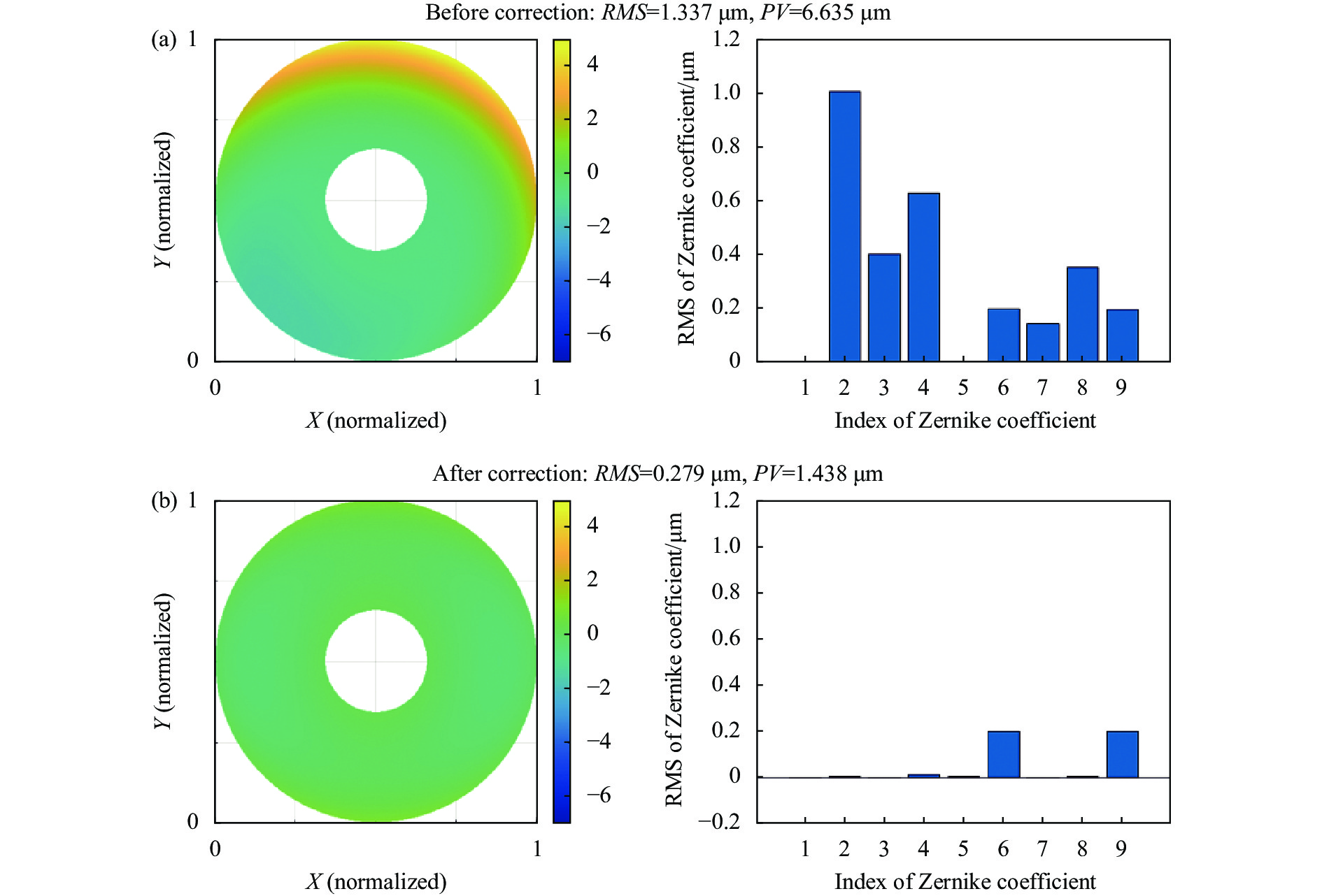
太阳望远镜在实际运行过程中的像差来源总是多种的,对包含了位置失配误差和非失配误差的多源混合误差的校正反映了次镜刚体位移在太阳望远镜运行过程中实际的校正效果,如图6所示。次镜刚体校正后,系统像差RMS值由1.337 μm降低至0.279 μm,剩余像差主要以Z9项球差和Z6项0°像散为主,次镜刚体位移对望远镜运行过程中多源混合误差也具有较好的校正效果。
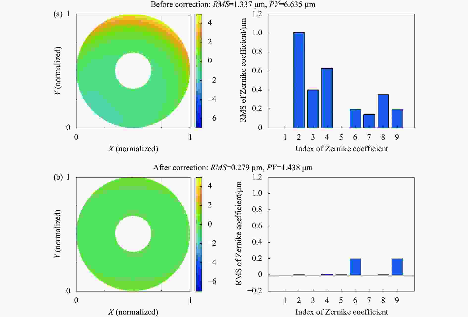
图 6 多源混合误差引起像差的的波前图和Zernike系数。 (a) 校正前; (b) 校正后
Figure 6. Wavefront diagram and Zernike coefficient of aberration caused by multi-source mixed error. (a) Before correction; (b) After correction
分析次镜刚体位移对位置失配误差、非失配误差、多源混合误差的校正情况,得到次镜刚体位移像差校正的总体原则:在校正某一像差时总会影响其他像差,这些像差也应被降低,或是其增大量小于那些被校正的像差,即校正后,系统像差的总RMS值降低。
-
实验使用与主镜同焦点的光源代替主镜,同时使用Hexapod对次镜的位移量进行控制,使用哈特曼相机对环境光进行标定,消除环境光的影响后,对轴上视场出瞳面波前像差进行测量。光路图和实际布局如图7所示。
文中研究的望远镜系统属于同轴系统,经过穿轴处理,并通过物像关系调整各个光学元件的前后间距,完成粗装调,并使用灵敏度矩阵法精装调后,在该位置重新测量灵敏度矩阵,通过随机调整光学元件的位置、改变变形镜面型的方式引入不同误差来源的像差,分别对位置失配像差、非位置失配像差、多源混合像差各进行了五组次镜刚体校正实验。

图 7 实验装置布局图
Figure 7. Layout of experimental device
-
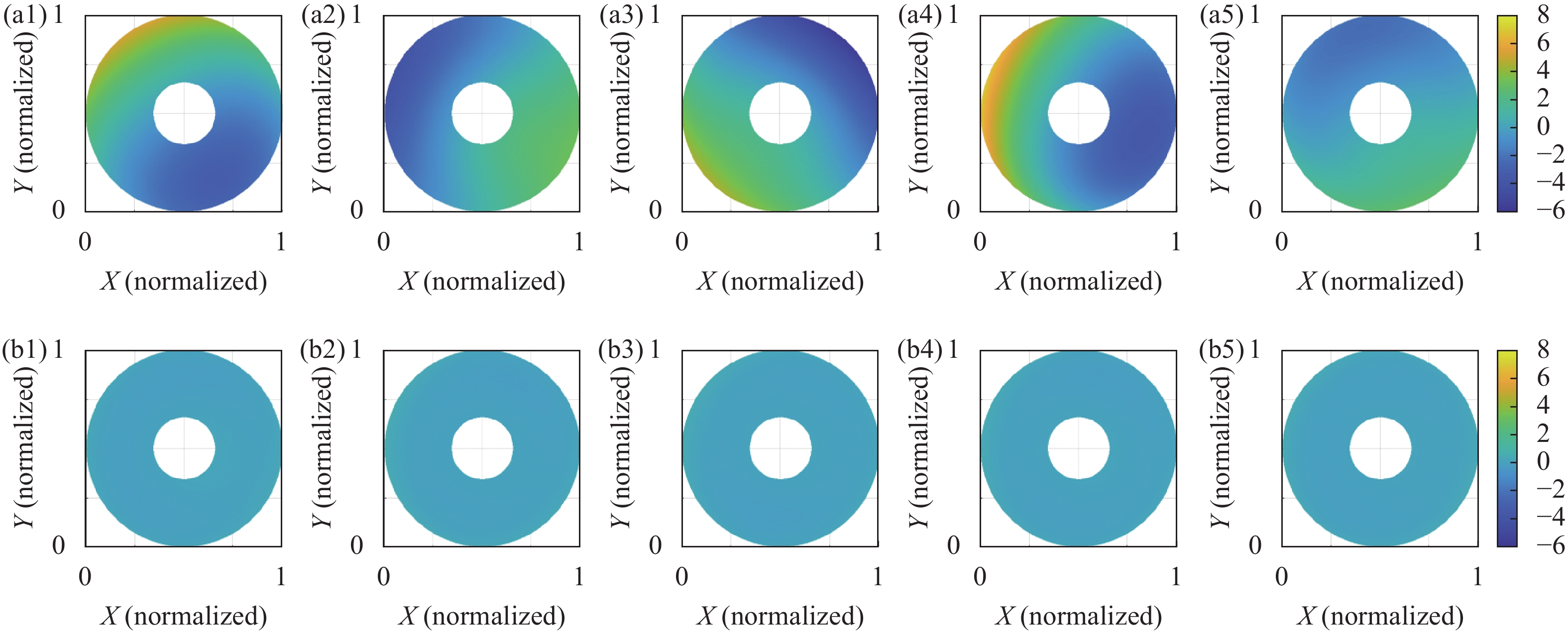
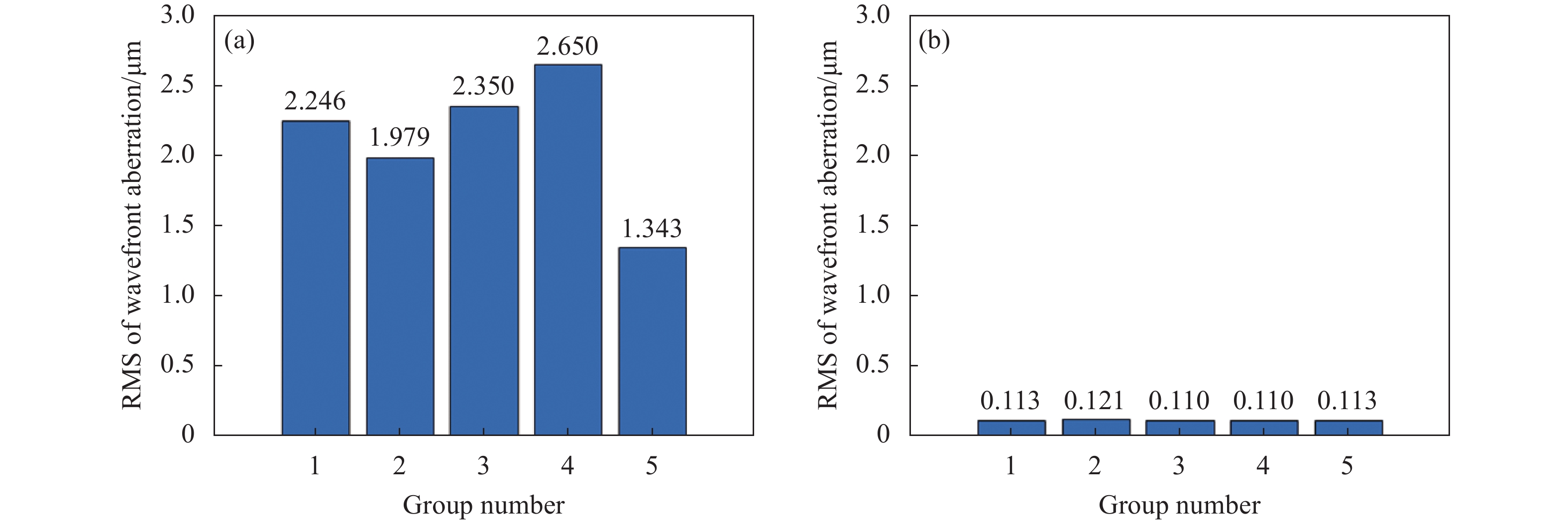
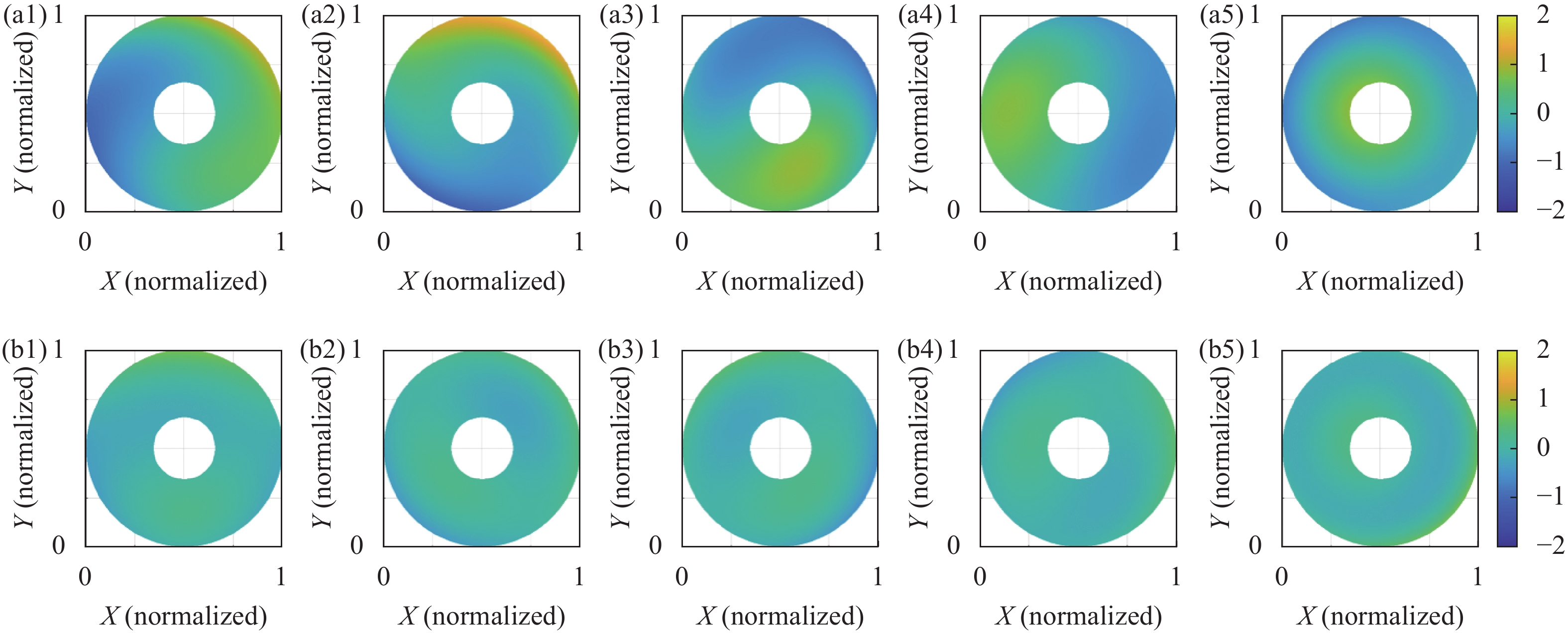
次镜刚体位移对五组位置失配误差的校正前后对比如图8和图9所示。次镜刚体位移对非失配误差有良好的校正效果,每组像差的RMS值均降低至原RMS值的9%以下。以剩余球差最小的第五组数据为例,对各项Zernike系数的前后变化进行研究,如表2所示,倾斜、离焦、彗差得到大量校正,剩余量受Hexapod精度影响无法降低,球差也得到了改善,由0.131 μm降低至0.089 μm,剩余像差主要以光路透镜引入的球差为主,分析灵敏度矩阵,降低剩余的球差会产生更大量的离焦,无法进一步校正。

图 8 位置失配误差引起像差的波前图校正前后对比。(a1)~(a5) 校正前;(b1)~(b5) 校正后
Figure 8. Wavefront diagram of aberration caused by position mismatch error. (a1)-(a5) Before correction; (b1)-(b5) After correction

图 9 位置失配误差引起像差的RMS值校正前后对比。(a) 校正前;(b) 校正后
Figure 9. RMS of aberration caused by position mismatch error. (a) Before correction; (b) After correction
表 2 第五组实验数据-位置失配误差引起像差校正(单位:μm)
Table 2. Group 5 experimental data-correction of aberration caused by position mismatch error (Unit: μm)
Z2 Z3 Z4 Z5 Z6 Z7 Z8 Z9 RMS Before correction −1.257 0.437 0.019 −0.050 −0.024 −0.111 0.020 0.131 1.343 After correction −0.001 0.018 0.044 −0.027 −0.033 −0.028 0.003 0.089 0.113 -
次镜刚体位移对五组非失配误差的校正前后对比如图10和图11所示。次镜刚体位移对非失配误差有较好的校正效果,每组像差的RMS值均降低至原RMS值的40%以下,以剩余球差最小的第六组数据为例,对各项Zernike系数的前后变化进行研究,如表3所示,倾斜、离焦得到了大量校正,Z8项Y方向彗差由0.148 μm降低至0.107 μm,但并未完全校正,分析灵敏度矩阵,其原因是Dx和Ty对Z2、Z8项的影响相同,校正Z8项会产生更大量的倾斜,故无法进一步校正。

图 10 非失配误差引起像差的波前图校正前后对比。(a1)~(a5) 校正前;(b1)~(b5) 校正后
Figure 10. Wavefront diagram of aberration caused by non-mismatch error. (a1)-(a5) Before correction; (b1)-(b5) After correction
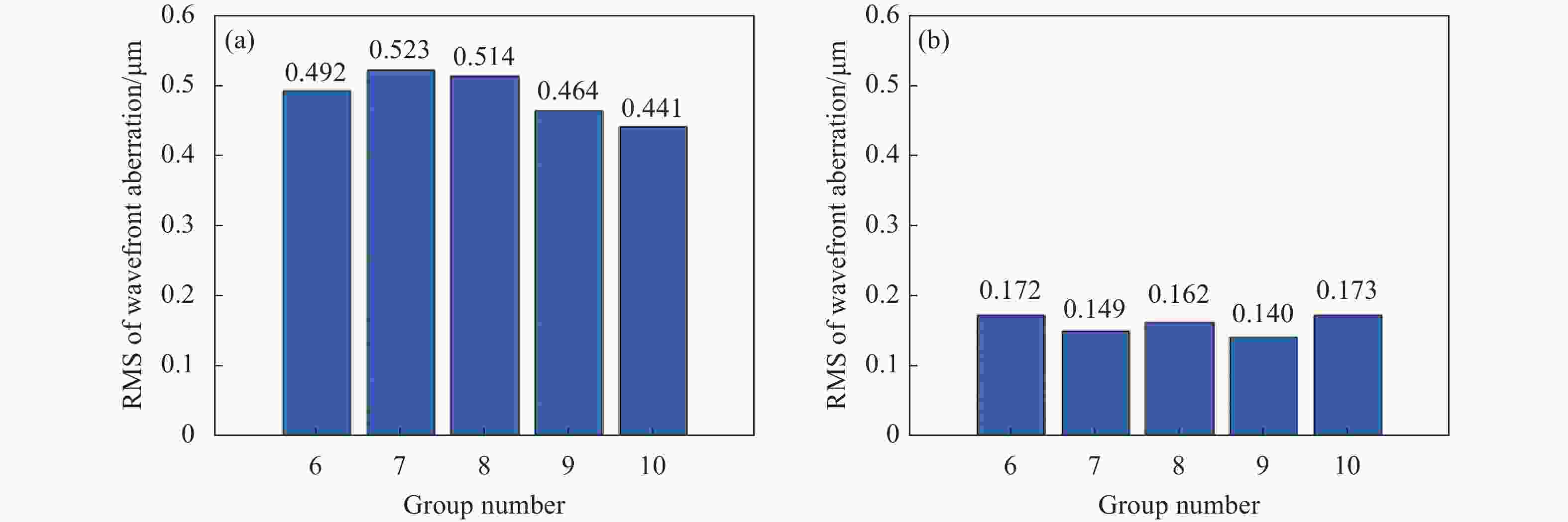
图 11 非失配误差引起像差的RMS值校正前后对比。(a) 校正前;(b) 校正后
Figure 11. RMS of aberration caused by non-mismatch error. (a) Before correction; (b) After correction
表 3 第六组实验数据-非失配误差引起像差校正(单位:μm)
Table 3. Group 6 experimental data-correction of aberration caused by non-mismatch error (Unit: μm)
Z2 Z3 Z4 Z5 Z6 Z7 Z8 Z9 RMS Before correction 0.016 0.443 0.103 −0.005 0.115 −0.001 0.148 0.012 0.492 After correction 0.031 0.036 0.037 0.006 0.121 −0.002 0.107 −0.008 0.172 -
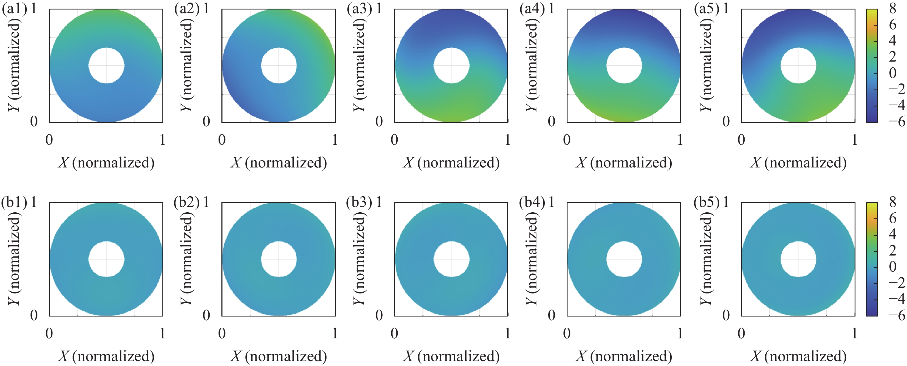
次镜刚体位移对五组多源混合误差的校正前后对比如图12和图13所示。次镜刚体位移多源混合像差有较好的校正效果,每组像差的RMS值均降低至原RMS值的15%以下,以初始像差值最大的第15组数据为例,对各项Zernike系数的前后变化进行研究,如表4所示,倾斜、离焦得到了大量校正,Z5、Z6项像散也得到了校正,分析灵敏度矩阵,其原因在于初始像差中存在较大量的倾斜,能够按一定比例校正像散。

图 12 多源混合误差引起像差的波前图校正前后对比。(a1)~(a5) 校正前;(b1)~(b5) 校正后
Figure 12. Wavefront diagram of aberration caused by multi-source mixed error. (a1)-(a5) Before correction; (b1)-(b5) After correction

图 13 多源混合误差引起像差的RMS值校正前后对比。(a) 校正前;(b) 校正后
Figure 13. RMS of aberration caused by multi-source mixed error. (a) Before correction; (b) After correction
表 4 第15组实验数据-多源混合误差引起像差校正(单位:μm)
Table 4. Group 15 experimental data-correction of aberration caused by multi-source mixed error (Unit: μm)
Z2 Z3 Z4 Z5 Z6 Z7 Z8 Z9 RMS Before correction −2.029 0.809 −0.576 −0.090 −0.054 −0.068 −0.009 0.127 2.265 After correction −0.023 −0.003 0.014 −0.012 −0.0007 0.102 −0.035 0.108 0.155 -
针对太阳望远镜在运行过程中由于位置失配、非失配误差引起低时空频率像差问题,提出了次镜刚体位移校正低时空频率像差的方法,并对三种不同来源像差进行了数值仿真及实验验证。结果表明:次镜刚体位移对动态位置失配误差引起像差的校正效果良好,校正后像差RMS值低于原值的9%;对非失配误差引起的像差也具有一定的校正效果,校正后像差RMS值低于原值的40%,其中对倾斜、离焦、彗差校正效果较好,对像散和球差的校正效果较差;对于多源混合误差,次镜刚体位移也具有较好的校正能力,校正后像差RMS值低于原值的15%。次镜刚体位移校正的方式能够在不增加光学元件的前提下降低太阳望远镜系统运行过程中的低时空频率像差,具有良好的发展前景和应用价值。
Low spatio-temporal frequency wavefront aberration correction technology of solar telescope
-
摘要: 针对大口径太阳望远镜系统运行过程中由于静态位置失配误差、风载弯沉等准静态位置失配误差以及热变形等非失配误差引起的波前像差导致成像质量下降的问题,在对太阳望远镜系统波前像差时空分频的基础上,提出采用次镜刚体位移对太阳望远镜低时空频率波前像差校正的方法,建立起次镜刚体位移与像差校正量的关系,并通过数值仿真及实验验证了采用次镜刚体位移对上述来源像差的校正能力。数值仿真和实验结果表明:次镜刚体位移能够对望远镜系统运行过程中的低时空频率波前像差进行有效校正,其中,对位置失配误差校正后像差RMS值低于原值的9%,对非失配误差校正后像差RMS值低于原值的40%,对多源混合误差校正后像差RMS值低于原值的15%。Abstract:
Objective Solar telescopes are important equipment for conducting solar physics research and predicting space weather. During operation, large aperture solar telescope systems are affected by factors such as optical and mechanical structural deformation caused by solar radiation, gravitational deflection in different directions, wind-borne optical structural deformation, and environmental temperature changes, resulting in wavefront aberrations, leading to significant degradation in the imaging quality of the solar telescope system, and restricting the resolution of solar atmospheric imaging. Adaptive optical systems are the main means of correcting low spatio-temporal frequency aberrations during the operation of solar telescopes, but their correction of low-order aberrations wastes a large amount of travel and sacrifices their ability to correct high-order aberrations. Therefore, it is necessary to correct the low spatio-temporal frequency aberrations during the operation of the solar telescope without increasing the complexity of the solar telescope system. Methods A simulation system and an experimental system have been established for the 60 cm POST solar telescope system. The sensitivity matrix of the displacement of the secondary mirror rigid body is calculated, and the low spatio-temporal frequency aberration is introduced using a deformable mirror to simulate low-order aberrations. The aberration of the optical system's field of view on the axis is observed using a Hartmann camera. The displacement of the secondary mirror rigid body required for correcting the aberration is calculated using the sensitivity matrix method. Finally, the introduced low spatio-temporal frequency aberration is corrected by adjusting the position of the secondary mirror rigid body. The results of the system fine assembly are shown (Fig.4). Results and Discussions The low spatio-temporal frequency aberrations for simulated solar telescope systems are corrected, the ability of secondary mirror rigid body displacement is quantitatively analyzed to correct different types of low-order aberrations, and the principles for correcting low spatio-temporal frequency aberrations are provided. The simulation results are verified through experiments, where the RMS value of the aberration after correction for the position mismatch error of the secondary mirror pair is lower than 9% of the original value (Fig.9), the RMS value of the aberration after correction for the non-mismatch error is lower than 40% of the original value (Fig.10), and the RMS value of the aberration after correction for the multi-source mixing error is lower than 15% of the original value (Fig.11). Conclusions A wavefront correction algorithm and implementation system for specific scenes have been constructed with adaptive optics. The real-time wavefront correction has been completed using a hexapod driven secondary mirror. The studies of correction for position mismatch error, non-mismatch error, and multi-source mixed error have been conducted, and multiple sets of experiments have been conducted. Without increasing the complexity of the optical system, the low spatio-temporal frequency aberration of the system has been reduced, and the imaging resolution of the solar telescope has been improved. The secondary mirror rigid body displacement correction method can reduce the low spatio-temporal frequency aberration during the operation of solar telescope systems without adding optical components, and has good development prospects and application value. -
Key words:
- imaging system /
- aberration correction /
- sensitivity matrix method /
- secondary mirror /
- solar telescope
-
图 3 Zernike系数受次镜五个自由度方向位移影响曲线图。 (a) x方向平移;(b) y方向平移;(c) z方向平移;(d) x方向旋转;(e) y方向旋转
Figure 3. Curve of Zernike coefficients affected by the displacement in the direction of five degrees of freedom of secondary mirror. (a) Translation around x axis; (b) Translation around y axis; (c) Translation around z axis; (d) Rotation around x axis; (e) Rotation around y axis
图 4 位置失配误差引起像差的波前图和Zernike系数。 (a) 校正前; (b) 校正后
Figure 4. Wavefront diagram and Zernike coefficients of aberration caused by position mismatch error. (a) Before correction; (b) After correction
图 5 非失配误差引起像差的波前图和Zernike系数。(a) 校正前; (b) 校正后
Figure 5. Wavefront diagram and Zernike coefficients of aberration caused by non-mismatch error. (a) Before correction; (b) After correction
图 6 多源混合误差引起像差的的波前图和Zernike系数。 (a) 校正前; (b) 校正后
Figure 6. Wavefront diagram and Zernike coefficient of aberration caused by multi-source mixed error. (a) Before correction; (b) After correction
图 8 位置失配误差引起像差的波前图校正前后对比。(a1)~(a5) 校正前;(b1)~(b5) 校正后
Figure 8. Wavefront diagram of aberration caused by position mismatch error. (a1)-(a5) Before correction; (b1)-(b5) After correction
图 9 位置失配误差引起像差的RMS值校正前后对比。(a) 校正前;(b) 校正后
Figure 9. RMS of aberration caused by position mismatch error. (a) Before correction; (b) After correction
图 10 非失配误差引起像差的波前图校正前后对比。(a1)~(a5) 校正前;(b1)~(b5) 校正后
Figure 10. Wavefront diagram of aberration caused by non-mismatch error. (a1)-(a5) Before correction; (b1)-(b5) After correction
图 11 非失配误差引起像差的RMS值校正前后对比。(a) 校正前;(b) 校正后
Figure 11. RMS of aberration caused by non-mismatch error. (a) Before correction; (b) After correction
图 12 多源混合误差引起像差的波前图校正前后对比。(a1)~(a5) 校正前;(b1)~(b5) 校正后
Figure 12. Wavefront diagram of aberration caused by multi-source mixed error. (a1)-(a5) Before correction; (b1)-(b5) After correction
图 13 多源混合误差引起像差的RMS值校正前后对比。(a) 校正前;(b) 校正后
Figure 13. RMS of aberration caused by multi-source mixed error. (a) Before correction; (b) After correction
表 1 望远镜参数
Table 1. Telescope parameters
Surface Mechanical diameter d/mm Radius of curvature r/mm Interval D/mm Conic factor Primary mirror 600 −2 040 −1320 −1 Secondary mirror 180 504.812 - −0.466  下载: 导出CSV
表 2 第五组实验数据-位置失配误差引起像差校正(单位:μm)
Table 2. Group 5 experimental data-correction of aberration caused by position mismatch error (Unit: μm)
Z2 Z3 Z4 Z5 Z6 Z7 Z8 Z9 RMS Before correction −1.257 0.437 0.019 −0.050 −0.024 −0.111 0.020 0.131 1.343 After correction −0.001 0.018 0.044 −0.027 −0.033 −0.028 0.003 0.089 0.113
下载: 导出CSV
表 3 第六组实验数据-非失配误差引起像差校正(单位:μm)
Table 3. Group 6 experimental data-correction of aberration caused by non-mismatch error (Unit: μm)
Z2 Z3 Z4 Z5 Z6 Z7 Z8 Z9 RMS Before correction 0.016 0.443 0.103 −0.005 0.115 −0.001 0.148 0.012 0.492 After correction 0.031 0.036 0.037 0.006 0.121 −0.002 0.107 −0.008 0.172
下载: 导出CSV
表 4 第15组实验数据-多源混合误差引起像差校正(单位:μm)
Table 4. Group 15 experimental data-correction of aberration caused by multi-source mixed error (Unit: μm)
Z2 Z3 Z4 Z5 Z6 Z7 Z8 Z9 RMS Before correction −2.029 0.809 −0.576 −0.090 −0.054 −0.068 −0.009 0.127 2.265 After correction −0.023 −0.003 0.014 −0.012 −0.0007 0.102 −0.035 0.108 0.155
下载: 导出CSV
-
[1] Shack R V, Thompson K. Influence of alignment errors of a telescope system on its aberration field[C]//Optical Alignment I. Proceedings of SPIE, 1980, 251: 146-153. [2] Thompson K. Description of the third-order optical aberrations of near-circular pupil optical systems without symmetry [J]. Journal of the Optical Society of America A, 2005, 22(7): 1389-1401. [3] Buchroeder R A. Tilted component optical systems[D]. Tucson: University of Arizona, 1976. [4] 鞠国浩. 离轴反射式天文望远镜主动光学波前控制方法研究[D]. 长春: 中国科学院研究生院(长春光学精密机械与物理研究所), 2017. Ju Guohao. Research of active optical wavefront control methods for off-axis reflective astronomical telescopes [D]. Changchun: Changchun Institute of Optics, Fine Mechanics and Physics, Chinese Academy of Sciences, 2017. (in Chinese) [5] 郭攀, 周军, 丁晓宇, 刘检华, 盛忠. 基于矢量波像差理论的两反系统装配失调解算方法[J]. 光学学报, 2019, 39(7): 0722002. doi: 10.3788/AOS201939.0722002 Guo Pan, Zhou Jun, Ding Xiaoyu, et al. Method to solve assembly misalignment of two-reverse system based on vector wave aberration theory [J]. Acta Optica Sinica, 2019, 39(7): 0722002. (in Chinese) doi: 10.3788/AOS201939.0722002 [6] 刘波, 丁亚林, 贾继强, 苏东风, 张雷. R-C光学系统的计算机辅助装调[J]. 红外与激光工程, 2016, 45(3): 318001-0318001(6). doi: 10.3788/irla201645.0318001 Liu Bo, Ding Yalin, Jia Jiqiang, et al. Computer aided alignment of R-C optical system [J]. Infrared and Laser Engineering, 2016, 45(3): 0318001. (in Chinese) doi: 10.3788/irla201645.0318001 [7] 左晓舟, 王章利, 赵金, 等. 两镜反射系统自适应装调技术研究[J]. 应用光学, 2022, 43(4): 780-786. Zuo Xiaozhou, Wang Zhangli, Zhao Jin, et al. Adaptive alignment technology of two-mirror reflection system [J]. Journal of Applied Optics, 2022, 43(4): 780-786. (in Chinese) [8] 王钰, 张新, 王灵杰, 等. 基于人工神经网络方法的自由曲面光学系统装调[J]. 光学学报, 2013, 33(12): 1211001. doi: 10.3788/AOS201333.1211001 Wang Yu, Zhang Xin, Wang Lingjie, et al. Freeform optical system alignment based on artificial neural networks [J]. Acta Optica Sinica, 2013, 33(12): 1211001. (in Chinese) doi: 10.3788/AOS201333.1211001 [9] 王彬, 伍凡, 叶玉堂. 离轴三反系统计算机辅助装调[J]. 红外与激光工程, 2016, 45(11): 1118006-1118006(7). doi: 10.3788/IRLA201645.1118006 Wang Bin, Wu Fan, Ye Yutang. Computer aided alignment for of-axis TMA system [J]. Infrared and Laser Engineering, 2016, 45(11): 1118006. (in Chinese) doi: 10.3788/IRLA201645.1118006 [10] 孙敬伟, 吕天宇, 姚丽双, 刘杰. 发射望远镜的设计与装调[J]. 光学精密工程, 2014, 22(2): 369-375. doi: 10.3788/OPE.20142202.0369 Sun Jingwei, Lv Tianyu, Yao Lishuang, et al. Design and assembly of transmitter-telescope [J]. Optics and Precision Engineering, 2014, 22(2): 369-375. (in Chinese) doi: 10.3788/OPE.20142202.0369 [11] 张向明, 姜峰, 孔龙阳, 等. 卡塞格林系统光学装调技术研究[J]. 应用光学, 2015, 36(4): 526–530. doi: 10.5768/JAO201536.0401006 Zhang Xiangming, Jiang Feng, Kong Longyang, et al. Research on optical alignment technology for Cassegrain system [J]. Journal of Applied Optics, 2015, 36(4): 526-530. (in Chinese) doi: 10.5768/JAO201536.0401006 [12] 顾志远, 颜昌翔, 李晓冰, 等. 改进的灵敏度矩阵法在离轴望远镜装调中的应用[J]. 光学精密工程, 2015, 23(9): 2595–2604. doi: 10.3788/OPE.20152309.2595 Gu Zhiyuan, Yan Changxiang, Li Xiaobing, et al. Application of modified sensitivity matrix method in alignment of off-axis telescope [J]. Optics and Precision Engineering, 2015, 23(9): 2595-2604. (in Chinese) doi: 10.3788/OPE.20152309.2595 [13] 曹宇泽, 马文礼. 两步式灵敏度矩阵法在卡塞格林望远镜装调中的应用[J]. 光电工程, 2020, 47(2): 180536. Cao Yuze, Ma Wenli. Application of two step sensitivity matrix method in Cassegrain telescope alignment [J]. Opto-Electronic Engineering, 2020, 47(2): 180536. (in Chinese) [14] 刘柱, 彭起, 任戈, 等. 一种基于二阶灵敏度矩阵的离轴望远镜装调法[J]. 激光与光电子学进展, 2022, 59(8): 0811002. Liu Zhu, Peng Qi, Ren Ge, et al. Second-order sensitivity matrix method for aligning off-axis telescopes [J]. Laser & Optoelectronics Progress, 2022, 59(8): 0811002. (in Chinese) [15] Rao C H, Gu N T, Liu Y Y, et al. POST—prototype for the Chinese Large Solar Telescope [J]. Journal of Astronomical Telescopes, Instruments, and Systems, 2019, 5(2): 024004. [16] Gu N T, Cheng L, Cheng Y T, et al. Thermal control for light-weighted primary mirrors of large ground-based solar telescopes [J]. Journal of Astronomical Telescopes, Instruments, and Systems, 2019, 5(1): 014005. [17] Rao C H, Gu N T, Rao C H, et al. First light of the 1.8-m solar telescope–CLST [J]. Science China Physics, Mechanics & Astronomy, 2020, 63(10): 109631. -

 点击查看大图

计量
- 文章访问数: 166
- HTML全文浏览量: 53
- PDF下载量: 25
- 被引次数: 0

