


-
激光切割技术[1−3]是利用高能量密度激光束对工件进行扫描,使得辐照区域的材料熔化、气化或分解,与此同时借助辅助气体吹除熔融残渣。因其加工精度高、非接触、适用材料范围大等优点[4−6],已广泛应用于航空、航天、汽车、轨道交通、新能源等领域[7−9]。因此激光精密切割成为了国内外学者的研究热点,针对加工参数的选择与调控,Chen等[10]通过实验方法探究光纤激光切割铝合金板的切割速度和光斑直径对切割质量影响,研究发现了不同厚度的铝合金板的最佳切割参数有所差异,在进光纤激光切割铝合金板时,应根据具体材料的性质和要求选择合适的切割参数,以获得最佳的切割效果,避免过度烧蚀和氧化等不良影响。Li等[11]在激光切割铝合金过程中,考虑了激光功率、切割速度和辅助气体压力等工艺参数对表面粗糙度、热影响区、力学性能、疲劳强度等的影响。
在激光切割缺陷分析方面,Sharma等[12]研究了光纤激光切割镀锌钢板过程中材料转移和表面性质的变化,发现激光功率和切割速度对切割表面质量和材料转移有显著影响,切割过程中的沉积物对表面质量也存在影响。Tahir等[13]采用CO2激光切割高强度钢,发现激光功率和切割速度对切割质量和机械性能的影响最为显著,以较低的切割速度在高功率下的切口处很容易产生熔渣粘附。Miraoui等[14]利用高功率激光切割不锈钢,研究发现激光功率、气体压力和切割速度都会影响表面质量和微观组织,其中功率是影响最显著的因素。为了进一步提高激光切割质量,Majid等[15]研究了激光切割过程中结构钢的热行为,研究结果表明切割功率和速度会影响熔池形态和深度,同时也会改变材料热影响区的大小和形状;通过热仿真分析研究了各种参数对材料传热特性的影响,包括切割速度、功率等,最终提出了优化建议。Buj-Corral等[16]通过多因素实验建立了回归模型,研究了不锈钢板的粗糙度、毛刺厚度以及尺寸误差随脉冲频率、脉宽、切割速度等因素变化的规律,发现对粗糙度和毛刺厚度影响最大的因素是脉冲频率,对尺寸误差影响最大的是脉宽。Scintilla等[17]采用响应面法拟合回归模型研究了光纤激光工艺参数对切缝粗糙度的影响,应用期望函数对切割质量和切割成本进行了优化。
随着工业领域金属薄壁构件设计的多样化,在高速激光切割的同时,对切口处的毛刺厚度和熔渣飞溅区宽度提出了更高的要求[18]。影响激光切割质量的因素较多,但目前很少有学者针对金属薄壁材料,探究离焦量、切割速度与激光功率等工艺参数对毛刺厚度和熔渣飞溅区宽度的综合交叉影响。文中针对0.2 mm厚度304不锈钢薄板进行激光切割实验研究,分析了毛刺和熔渣飞溅区产生的机理,通过调控切割速度、激光功率、离焦量等工艺参数,分别对304不锈钢板激光切割工件的毛刺厚度和熔渣飞溅区宽度变化规律进行归纳,通过工艺优化获得最佳加工参数组合。对金属薄壁材料的不同装夹形式进行实验对比,将最佳工艺参数进行验证,根据不同的表面形貌质量确定合理的装夹方式,为金属薄壁材料的实际加工提供理论基础。
-
研究中采用的实验材料为厚度为0.2 mm的304不锈钢,其中基础元素为铁,合金元素主要为镍和铬。304不锈钢具有优异的耐腐蚀性、耐热性以及良好的机械性能。实验采用的连续光纤激光加工设备最大输出功率为1.5 kW,激光束波长为(1070±10) nm,工作模式可选连续或调制型。激光切割头X、Y轴行程分别为400 mm和500 mm,冷却方式为水冷。高压辅助气体与激光光束同轴,所用气体为纯度99.99%的N2,切割喷嘴出口直径1.0 mm,其中切割工艺参数如表1所示。实验结束后,采用光学显微镜对毛刺厚度和熔渣飞溅区宽度进行观察和测量。每个实验材料取其中最为明显的3个位置进行测量,最后取其平均值进行分析。
表 1 切割工艺参数表
Table 1. Cutting process parameters table
Cutting parameters Values P/W 48, 60, 75, 90, 100, 125, 190, 255, 320 v/m·min–1 8, 10, 12, 14 h/mm −0.1, −0.2, −0.3, −0.5, 0, 0.1, 0.2 p/MPa 0.2, 0.4, 0.6, 1, 1.2 Note: P—Laser power, v—Cutting speed, h—Defocus amount, p—Gas pressure -
激光与材料的相互作用伴随着材料吸收激光能量,发生熔融、气化、电离乃至原子化学键断裂等过程。采用激光切割不锈钢薄板时,当材料吸收激光能量达到烧蚀阈值后发生熔化,材料对激光的吸收率会大幅度提高从而导致温度急剧上升,一部分的材料会产生气化现象,但材料的主要去除机制还是液态喷溅。如果辅助气体压力和重力的联合动力大于切缝的表面张力,熔渣将会被吹除切缝,否则将会形成毛刺附着于切缝底部。在不同的激光切割速度下,随着激光功率的不断增加,毛刺厚度展现出如图1(a)所示的较为线性的上升趋势,其中当激光功率低于48 W时,由于激光功率不足,在加工过程中未能穿透材料,所以在图形中未进行展示。

图 1 (a) 不同速度下功率与毛刺厚度的关系;(b) 不同功率下速度与毛刺厚度的关系
Figure 1. (a) Relationship between power and burr thickness at different speeds; (b) Relationship between speed and burr thickness at different powers
图1(b)为不同的激光功率下,毛刺厚度随切割速度变化所呈现的规律。可以观察到随着切割速度的增大,毛刺厚度表现出先下降后上升的变化趋势,当切割速度大于10 m/min,材料吸收的激光能量下降,切口前端位置处激光扫描速度大于金属的熔化速度,熔融物的温度降低且出现了一定的滞后,熔融物的粘性增大,辅助气体主要起到冷却的作用,使熔融物不易被吹除,导致毛刺厚度增大。
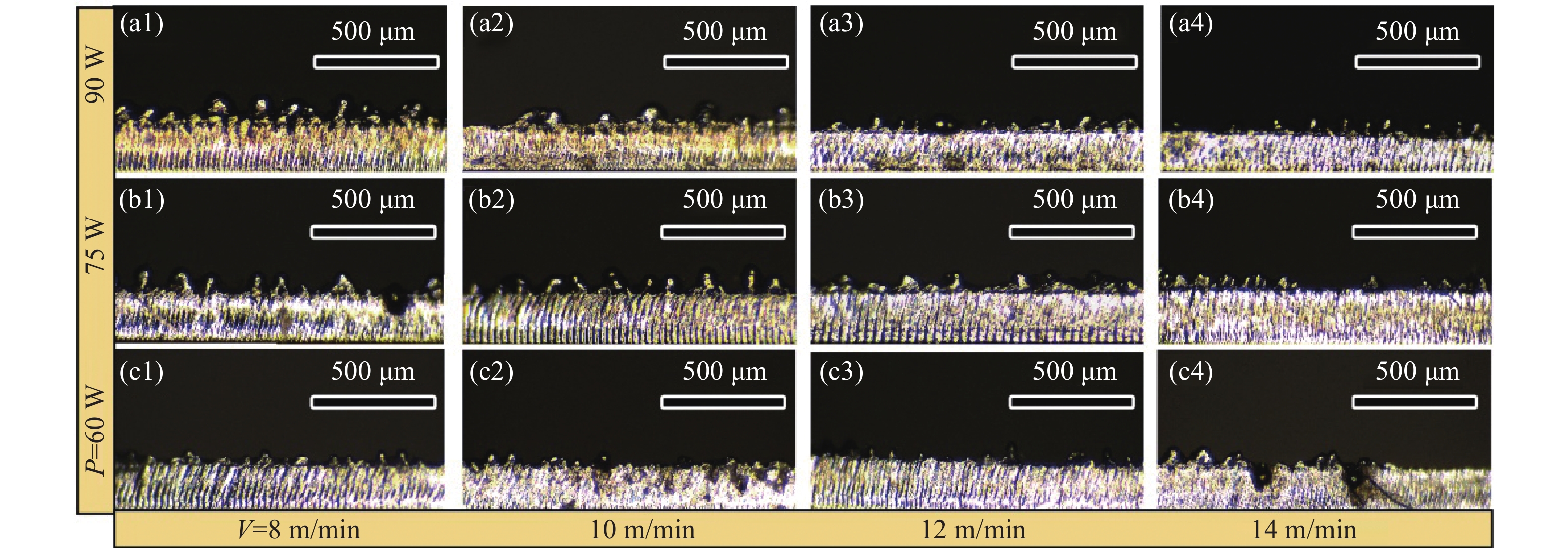
图2为不同激光功率下毛刺厚度的对比图。在离焦量为0的相同条件下,当激光功率低于48 W时,激光中心区域内的能量密度小于材料的烧蚀阈值,导致材料无法被切透。随着激光功率的提高,激光能量密度上升,单位面积上吸收的能量增加,材料的烧蚀更加充分且熔融物增多,熔融物的表面张力增大,形成大体积球状熔渣,如图2(a)所示。当切割速度在8~10 m/min范围内,随着激光功率的升高毛刺厚度基本呈现出波动递增的趋势,因为激光的扫描速度较低,光束与材料的作用时间较长,材料易吸收过多的激光能量使熔池内温度升高而发生过烧蚀现象,造成毛刺厚度增大。当扫描速度继续升高至12~14 m/min范围内,毛刺厚度大体呈现出先上升后下降的趋势。切割速度的提高可以有效的降低热量的输入,有效降低球状熔渣的体积,使毛刺厚度下降。
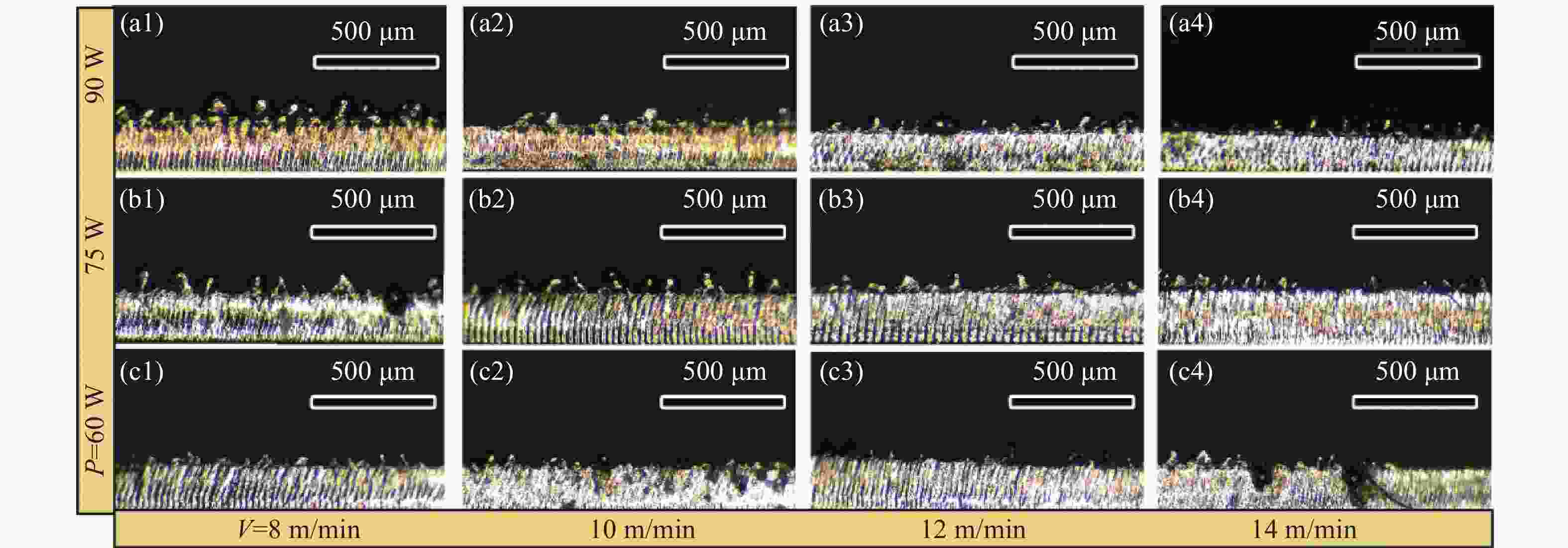
图 2 不同功率下的毛刺厚度对比。(a1)~(a4) 90 W;(b1)~(b4) 75 W;(c1)~(c4) 60 W
Figure 2. Comparison of burr thickness at different powers. (a1)-(a4) 90 W; (b1)-(b4) 75 W; (c1)-(c4) 60 W
-
在辅助气体压强为1.0 MPa的状态下,选取激光功率为60 W,调制频率为5000 Hz。图3(a)为不同的切割速度下,毛刺厚度随不同离焦量的变化规律。材料表面与聚焦透镜几何焦点之间的距离为离焦量,工件材料的上表面离焦量定义为0,当几何焦点在材料内部为“−”(负离焦),在材料表面之上为“+”(正离焦)。

图 3 (a)不同速度下离焦量与毛刺厚度的关系;(b)不同离焦量下速度与毛刺厚度的关系
Figure 3. (a) Relationship between defocus amount and burr thickness at different speeds; (b) Relationship between cutting speed and burr thickness at different defocus amounts
保持其他条件不变,当离焦量为–0.2 mm,切割速度低于8 m/min时,可以有效切透板材,经测量其毛刺厚度为26 μm。
随着激光焦点从负离焦转换为正离焦,毛刺厚度呈现线性的上升趋势。在激光切割过程中,材料表面在吸收激光能量后迅速升温熔化,随着温度的升高,材料的热容、导热系数以及对激光的吸收率均发生了改变,材料表面对激光能量的吸收增大,导致能量在沿着材料厚度方向上迅速衰减,激光能量密度显著下降,材料底部熔融不充分,切割面粗糙,毛刺厚度增大而且切面条纹出现分层的现象,板材表面吸收足够的激光能量后充分熔化,出现窄而紧凑的细小条纹,底部则出现倾斜的粗大条纹。
图3(b)为不同离焦量下,毛刺厚度随切割速度改变的变化规律。选取辅助气体压强为1.0 MPa,激光功率60 W,调制频率5000 Hz。从图中可以观察到,当激光的焦点在正离焦,材料的表面首先吸收激光能量形成熔池,当扫描速度为8 m/min,切缝表面出现了过烧蚀现象使得板材被氧化变色,同时切面的条纹较为细腻,底部较为粗大,且出现了明显的分层现象。而随着切割速度的增加,材料吸收的激光能量减少,毛刺厚度也出现了先下降后上升的趋势,速度为10 m/min是一个拐点,毛刺厚度最小。
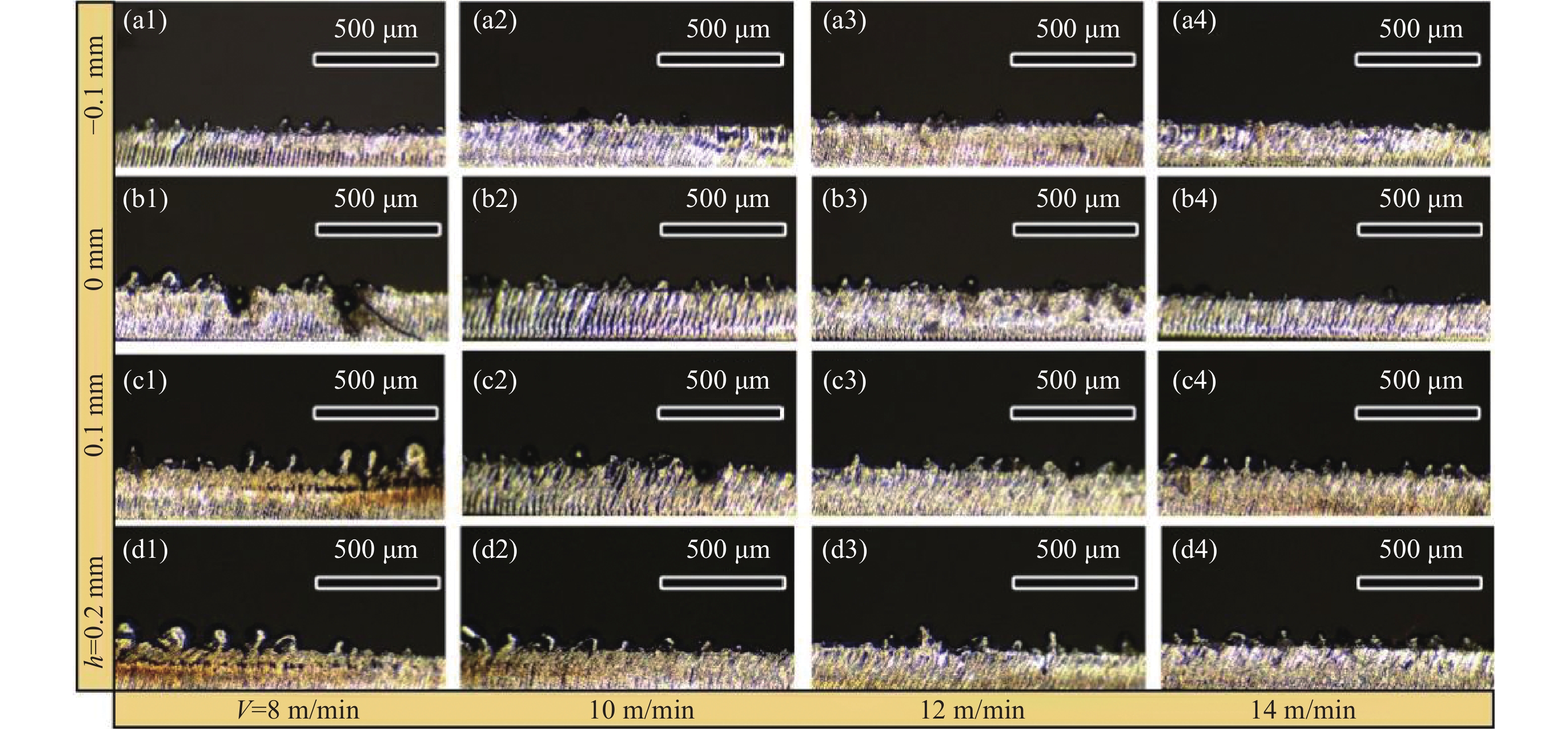
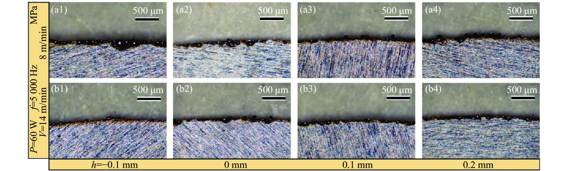
图4为不同离焦量下毛刺厚度的对比图。相较于正离焦加工,负离焦则表现出较好的切割质量,但离焦量为−0.2 mm,切割速度在10~14 m/min范围内,工件材料无法被切透,当切割速度低于8 m/min时,才能够有效的切透板材。考虑到焦点在工件下方,激光能量在离焦后发散,材料表面因为激光能量密度降低而无法达到烧蚀阈值,所以材料无法被切透。在负离焦位置,可以通过降低扫描速度,增大材料与激光作用的时间,或者增大激光功率充分切透板材。

图 4 不同离焦量下的毛刺厚度对比。(a1)~(a4) −0.1 mm;(b1)~(b4) 0 mm;(c1)~(c4) 0.1 mm;(d1)~(d4) 0.2 mm
Figure 4. Comparison of burr thickness at different defocus amounts. (a1)-(a4) −0.1 mm; (b1)-(b4) 0 mm; (c1)-(c4) 0.1 mm; (d1)-(d4) 0.2 mm
-
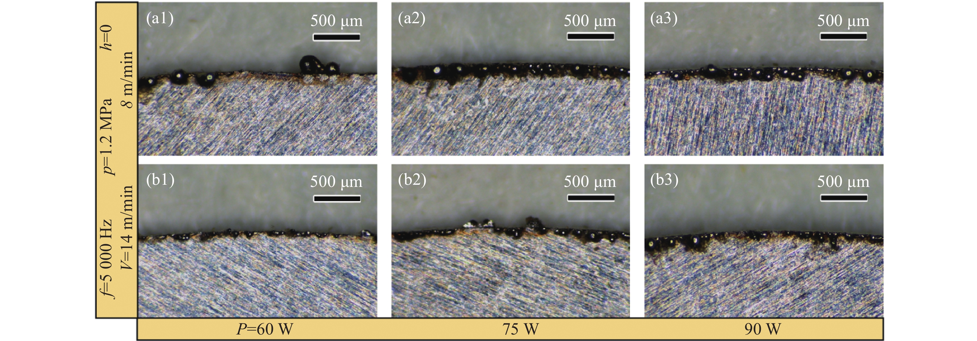
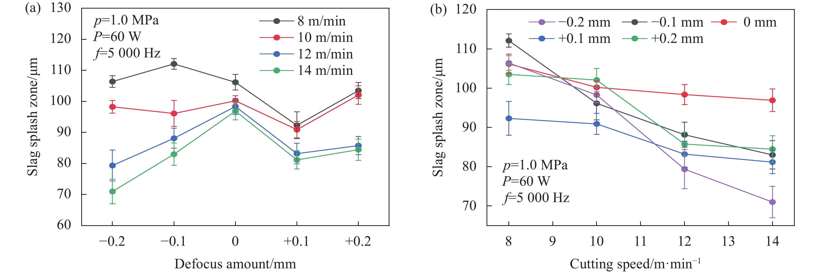
文中对于熔渣飞溅区的定义为包含激光切割热影响区在内的重铸层覆盖范围。观察图5(a)可以发现,在不同的切割速度下,随着激光功率的增大,熔渣飞溅区宽度呈现出稳定的上升趋势,其中最大的熔渣飞溅区在功率为90 W,速度为8 m/min,达到最大值146 μm。增大切割速度可以显著的降低熔渣飞溅区宽度,最小可在切割速度为14 m/min,功率为60 W时达到最小值91.6 μm。这种现象是因为随着激光功率的提升材料吸收的激光能量增大,从而提高辐照位置材料的温度,随着熔融材料温度的升高,相应的热影响区宽度也出现增大的现象。
图5(b)为不同激光功率下,熔渣飞溅区宽度随不同切割速度的变化情况。当激光功率为48 W,激光无法切透工件材料所以没有出现熔渣飞溅的区域,但是经过激光束的照射材料表面温度升高,在基体上产生了不同程度的热影响区。其余的熔渣飞溅区宽度随着切割速度的增大都展现出线性下降的趋势。造成这种现象的原因是在激光功率和辅助气体压强不变的情况下,随着切割速度的增大,激光与工件材料的相互作用时间变短,吸收的激光能量下降,熔渣飞溅区也相应的减少。与此同时热扩散效应减弱,在辅助气体N2的作用下材料迅速降温冷却,所以随着切割速度的增大,热影响区宽度也逐渐减小。图6为不同激光功率下熔渣飞溅区宽度的对比图。
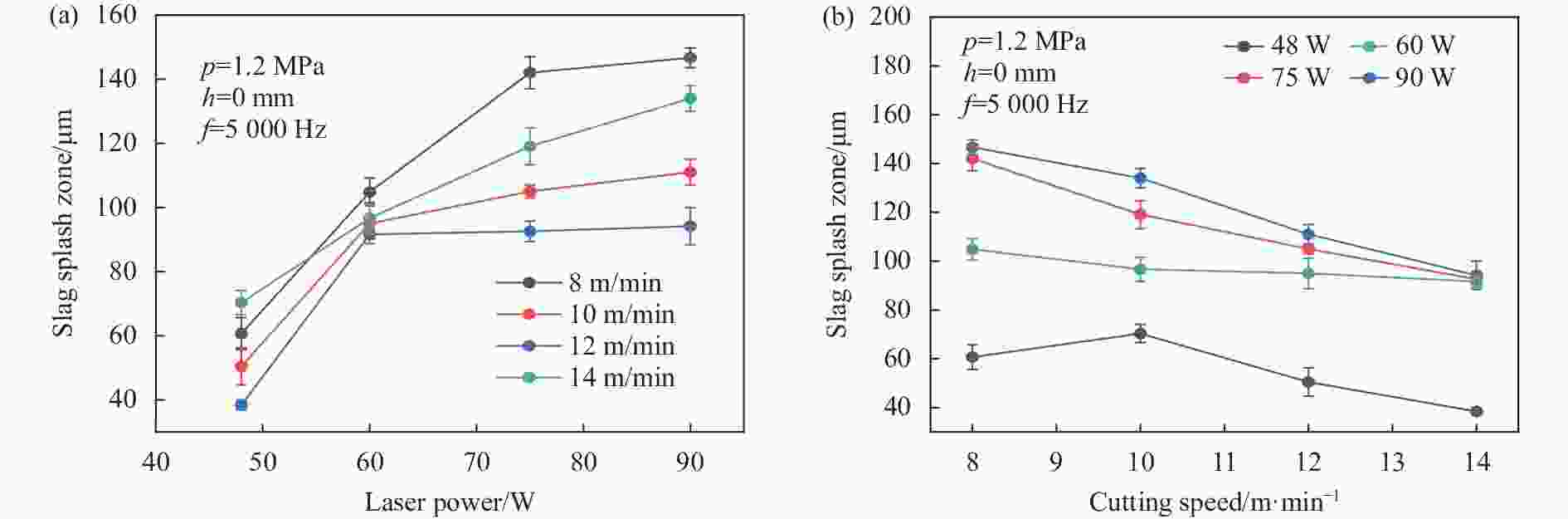
图 5 (a) 不同速度下功率与熔渣飞溅区的关系;(b) 不同功率下速度与熔渣飞溅区的关系
Figure 5. (a) Relationship between power and slag splash zone at different speeds; (b) Relationship between cutting speed and slag splash zone at different powers

图 6 不同功率下的熔渣飞溅区宽度对比。(a1)、 (b1) 60 W;(a2)、 (b2) 75 W;(a3)、(b3) 90 W
Figure 6. Comparison of slag splash zone width at different powers. (a1), (b1) 60 W; (a2), (b2) 75 W; (a3), (b3) 90 W
-
选取激光功率为60 W,辅助气体压强为1.0 MPa,调制频率为5000 Hz。图7(a)为离焦量对熔渣飞溅区宽度的影响规律。当离焦量为−0.2 mm,由于激光功率过小而未达到材料的烧蚀阈值,造成材料无法被切透,其余的离焦量下,熔渣飞溅区的变化比较小,皆在一个范围内波动,数值较为稳定。正离焦相对于焦平面加工的熔渣飞溅区出现了减小的趋势,造成这种现象的原因是正离焦的激光束聚集在材料表面的能量较为分散,沿材料深度方向的热传导分散效应更加明显,所以出现热影响区和熔渣飞溅区变小的现象。
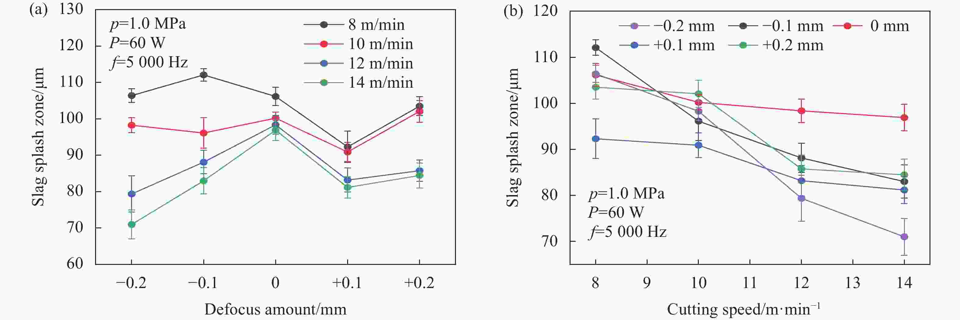
图 7 (a) 不同速度下离焦量与熔渣飞溅区的关系;(b)不同离焦量下速度与熔渣飞溅区的关系
Figure 7. (a) Relationship between defocus amounts and slag splash zone at different speeds; (b) Relationship between cutting speed and slag splash zone at different defocus amounts
图7(b)为不同离焦量下,熔渣飞溅区宽度随切割速度的变化规律。可以观察到,随着切割速度的增大,熔渣飞溅区宽度呈现线性的下降趋势,同时在负离焦下热影响区宽度下降显著且幅度更大。图8为不同离焦量下熔渣飞溅区宽度的对比图。

图 8 不同离焦量下的熔渣飞溅区宽度对比。(a1)、 (b1) −0.1 mm;(a2)、(b2) 0 mm;(a3)、 (b3) 0.1 mm;(a4)、(b4) 0.2 mm
Figure 8. Comparison of slag splash zone width at different defocus amounts. (a1), (b1) −0.1 mm; (a2), (b2) 0 mm; (a3), (b3) 0.1 mm; (a4), (b4) 0.2 mm
-
根据上述的实验规律可得,激光焦点处于负离焦,切割速度为10 m/min,毛刺厚度较小、熔渣飞溅区宽度较窄,可以获得较好的表面形貌。但是在负离焦状态,激光功率不足会出现无法切透材料的现象,所以下述实验中将会增大激光功率并改变离焦量,对比切割效果。具体参数及实验结果如表2所示,图9、10为两组实验结果的对比图。
表 2 对照实验结果表
Table 2. Controlled experimental results table
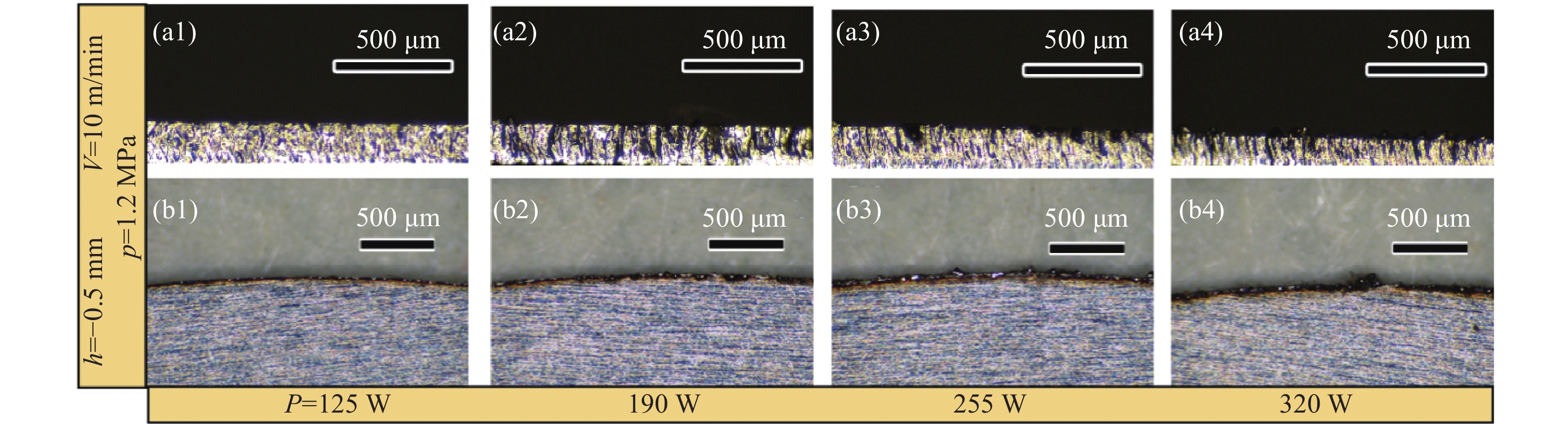
Number P/W h/mm Thickness of burr/μm Width of slag splash/μm 1 90 −0.3 0 0 2 125 −0.3 9.3 44.3 3 190 −0.3 10.7 67.3 4 255 −0.3 47.3 98.7 5 320 −0.3 61 105.7 6 90 −0.5 0 0 7 125 −0.5 10 37.3 8 190 −0.5 30.6 71 9 255 −0.5 54.3 85 10 320 −0.5 69.7 90.7 由表2实验结果可以观察到,不锈钢薄板在负离焦的状态下切缝垂直度较好且具有良好的表面形貌,且热影响区域小,无脆性断裂。伴随激光功率的增加,熔渣飞溅区宽度和毛刺厚度都呈线性增加趋势。激光功率为90 W,离焦量为−0.3 mm和−0.5 mm皆无法切透材料。当离焦量为−0.3 mm,熔渣飞溅区宽度相较于−0.5 mm有少量的增加,比较稳定的在一个范围内波动。当激光功率为125 W,板材沿着厚度方向吸收到足够的激光能量后从而产生窄而细腻的切面条纹,且毛刺和熔渣飞溅区显著减小。离焦量分别为−0.3 mm与−0.5 mm对应的毛刺厚度基本一致,而离焦量为−0.5 mm的热影响区宽度则明显大于离焦量为−0.3 mm。
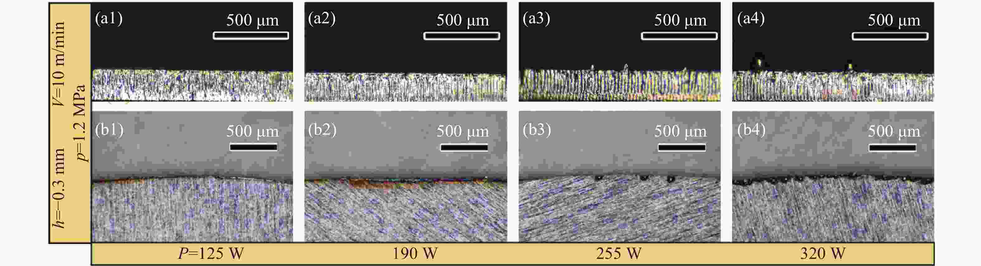
图 9 离焦量为−0.3 mm时毛刺厚度与熔渣飞溅区宽度。(a1)~(a4) 毛刺厚度;(b1)~(b4) 熔渣飞溅区宽度
Figure 9. Burr thickness and slag splash zone width when defocus amount is −0.3 mm. (a1)-(a4) Burr thickness; (b1)-(b4) Slag splash zone width

图 10 离焦量为−0.5 mm时毛刺厚度与熔渣飞溅区宽度。(a1)~(a4)毛刺厚度;(b1)~(b4)熔渣飞溅区宽度
Figure 10. Burr thickness and slag splash zone width when defocus amount is −0.5 mm. (a1)-(a4) Burr thickness; (b1)-(b4) Slag splash zone width
-
文中激光切割不锈钢薄板的装夹方式主要有两种,分别是采用气动压紧式和衬垫式进行装夹。气动压紧式是在待加工板材的左右各安装一个可移动的卡槽,薄板材料在卡槽里装夹完毕后使用气缸压紧,随后将卡槽用螺栓固定,限制板材各个方向的自由度,在待加工板材的下方安装有支撑板来平衡板材被压紧后的弹性变形。衬垫式装夹是在待加工板材的下方使用铝合金蜂窝板作为激光切割的支撑件。在激光同轴辅助气体的作用下,使得待加工材料与支撑件充分贴合,可以避免加工板材的微小变形导致的加工误差。
-
采用气动压紧装置进行加工过程中,为避免辅助气体压强过大导致不锈钢薄板发生弹性变形,实验利用单因素实验法,采用上述研究得出的最佳工艺参数,进行不同辅助气体压强切割的对比实验,考虑到切缝较窄,为防速度过快而导致熔融物无法完全吹离切缝形成毛刺,本次实验的切割速度调整为8 m/min,初始的辅助气体压强从0.2 MPa开始递增,探究不同的气体压强对板材形貌质量以及变形情况的影响,加工工艺参数如表3所示。
表 3 气动压紧式切割工艺参数表
Table 3. Process parameters of pneumatic tight cutting
Number P/W v/m·min-1 h/mm p/×105 Pa 1 125 8 −0.3 2, 4, 6 由对照实验结果图11可知,在激光加工的过程中,辅助气体压强为0.2 MPa,不锈钢薄板下方的可移动的支撑板能够平衡辅助气体带来的作用力,加工完成的薄板并未发生明显的热变形,但是由于辅助气体压强过小,激光与板材发生作用后,无法有效的将熔融物吹离切缝,导致材料的熔渣在切缝处滞留,部分熔渣与板材黏连在一起,并在切缝背部形成了致密的毛刺层。
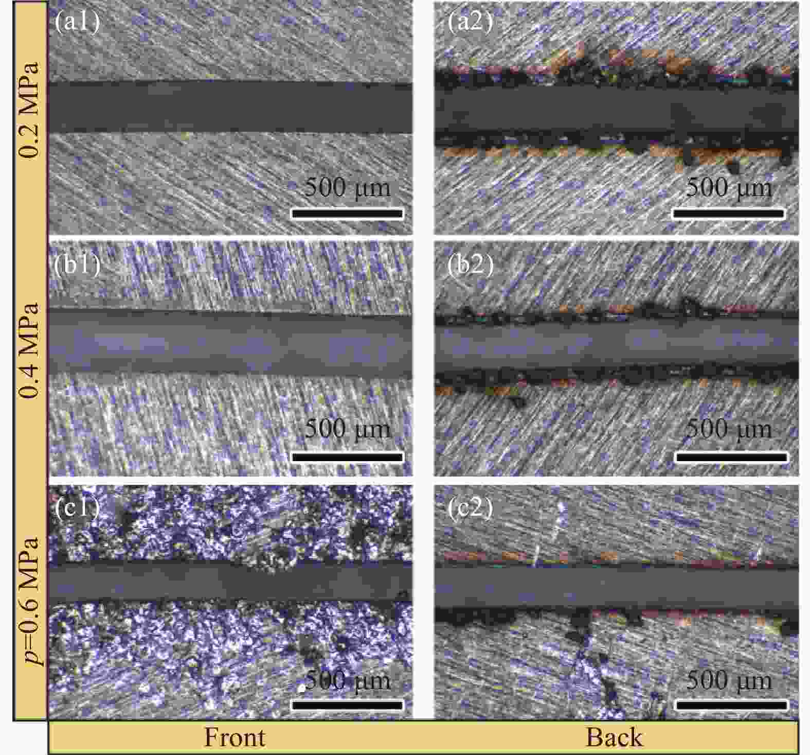
图 11 气动压紧式激光切割实验结果。(a1)、 (a2) 0.2 MPa;(b1)、(b2) 0.4 MPa;(c1)、 (c2) 0.6 MPa
Figure 11. Experimental results of laser cutting with pneumatic clamping type. (a1), (a2) 0.2 MPa, (b1), (b2) 0.4 MPa, (c1), (c2) 0.6 MPa
当辅助气体压强上升到0.4 MPa,板材发生了明显的翘曲现象,且上表面覆盖了一层白色的氧化物。伴随着激光切割头的移动,同轴辅助气体向板材施加的作用力已经无法被下方的支撑板所平衡,完成切割的部分在辅助气体的作用下受到压力。当激光切割头移动,板材会发生不同程度的弹性变形并翘曲,翘曲的板材会干涉激光切割头的移动。如果翘曲的幅度足够大,可能碰触激光切割头并导致设备停止运行,同时激光切割头的高温会与板材翘曲的部分发生二次作用,在表面形成一层白色的氧化物。随着辅助气体压强增大,气体排渣能力提高,减小了挂渣量。随着气体压强的继续增大,板材发生了明显的弹性变形,翘曲现象严重,材料上表面形成了大量的白色氧化物。
根据上述实验现象,总结出采用气动压紧装置进行加工,在较小的气体压强下,板材上下平面的受力可以达到平衡,在板材上表面不会形成白色的氧化物,但下表面的毛刺厚度较大。随着气体压强的增大,板材开始发生弹性变形现象并出现了白色的氧化物,但气压的增大直接增强了熔渣排除能力,挂渣量随着气压的增加而逐渐减小。
-
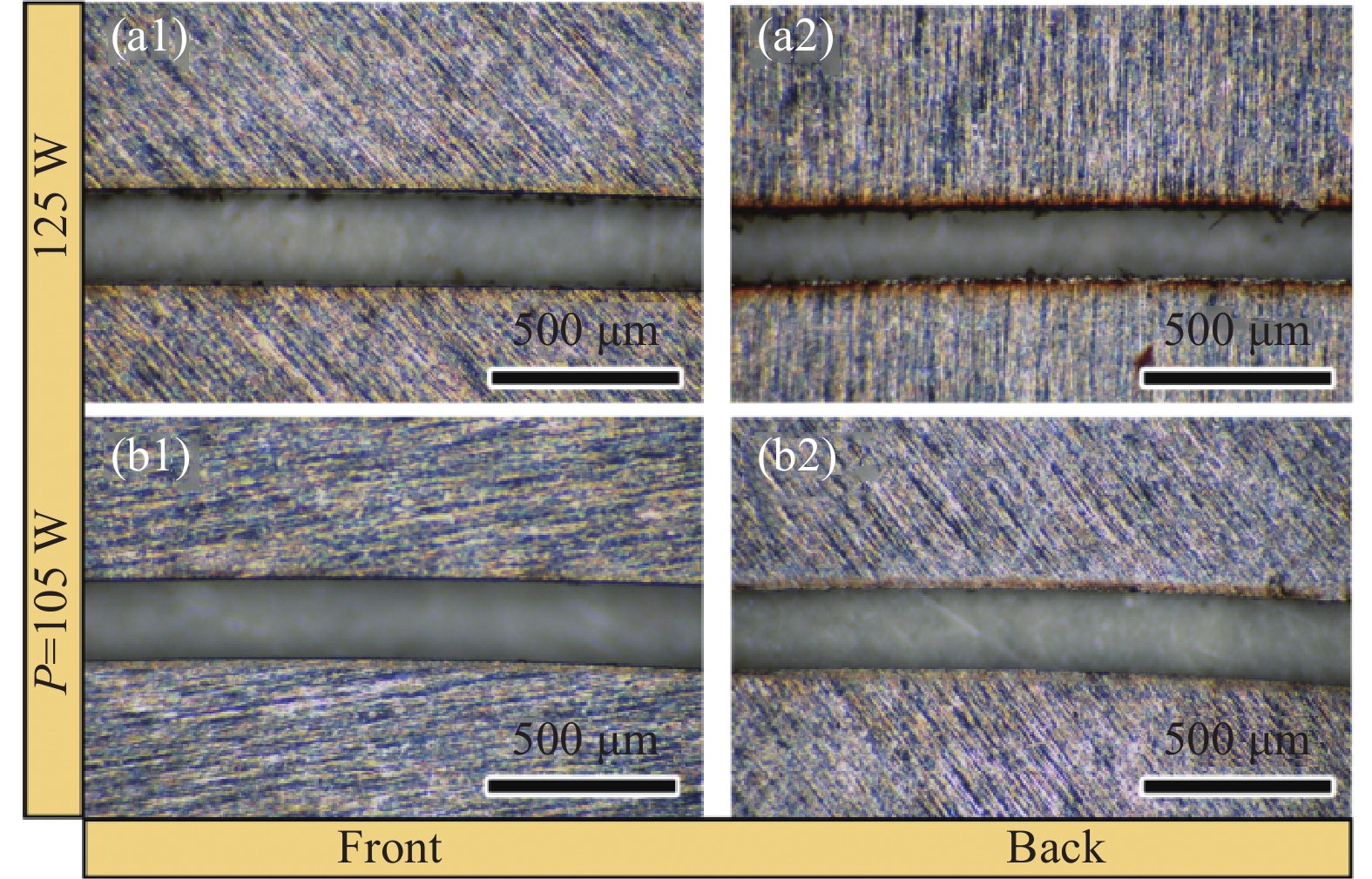
为了对比不同装夹形式对激光切割效果的影响,采用铝合金蜂窝板作为板材下方的支撑件。具体实验参数如表4所示。如图12所示,两种工艺参数下的切缝整体形貌、粗糙度以及毛刺厚度皆差距不大。在激光功率为125 W,切缝的底面存在一定的过烧蚀现象,当激光功率较大,激光与板材的相互作用会发生的更加剧烈,烧蚀也更加充分,但由于切缝十分狭窄,辅助气体到达工件表面后会被反弹一部分从而减弱了气流的排渣能力。适当的减小激光功率,保证激光对板材充分作用的前提下,避免激光过烧蚀现象的发生,可以提高板材的表面粗糙度。
上述实验现象表明当所需加工板材的形状较为简单且对精度的要求不高,可以采用气动压紧式进行加工,减小辅助气体的排放量从而减少加工成本。当加工的图形较为复杂且精度要求较高,需要采用衬垫式进行加工,板材的整体形貌质量、粗糙度以及热影响区都可以得到控制,没有明显的热变形,切口宽度均匀,并且足够的气体压强可以有效的将熔渣吹离切缝,避免在下表面滞留,板材上表面也可以有效的避免因板材翘曲而生成白色氧化物。
表 4 衬垫式切割工艺参数表
Table 4. Liner type cutting process parameter table
Number P/W v/m·min-1 h/mm p/×105 Pa 1 105 8 −0.3 12 2 125 8 −0.3 12 
图 12 衬垫式激光切割实验结果。(a1)、(a2) 125 W;(b1)、 (b2) 105 W
Figure 12. Experimental results of laser cutting with liner type. (a1), (a2) 125 W; (b1), (b2) 105 W
-
文中采用连续光纤激光器对0.2 mm厚度304不锈钢薄板进行切割实验,研究了激光加工参数对毛刺堆积量和熔渣飞溅区宽度的作用规律,得到以下结论:
1)毛刺厚度随着激光功率、离焦量的增大而增加,随着切割速度的增大先降低后增加。熔渣飞溅区宽度随着激光功率的增大而增加,随着切割速度的增大而降低,随着离焦量的增大出现小范围波动。当激光功率为125 W,切割速度为10 m/min,辅助气体压强为1.2 MPa,离焦量为−0.3~−0.5 mm,可以获得较好的加工效果。
2)对比了不同装夹形式对激光切割效果的影响,气动压紧式加工中,由于板材承受高气体压强的作用,板材发生翘曲变形现象;衬垫式加工的板材整体形貌质量、粗糙度以及热影响区都可以得到控制,没有明显的热变形,切口宽度均匀,且有效避免了翘曲及氧化现象。
3)综合考虑,针对金属薄壁材料,切割速度在8~10 m/min,激光功率在105~125 W区间,切口宽度均匀,可以获得较好的加工效果。对于较厚的金属板材,可适当的降低切割速度以及离焦量,并提高激光功率,来提高加工质量。对于形状较为复杂且精度要求较高的多线条图形,可适当降低激光功率以及气体压强,避免功率过大对窄缝零件造成过蚀现象。
Technics of continuous-wave fiber laser cutting of thin-wall metal materials
-
摘要: 随着工业领域金属薄壁构件设计的多样化,在高速激光切割的同时,对切口形貌质量也提出了更高的要求。本研究采用连续光纤激光器对0.2 mm厚度304不锈钢薄板进行切割实验,研究了毛刺和熔渣飞溅区产生的机理,重点讨论了加工工艺参数中的激光功率、切割速度、离焦量对毛刺堆积量和熔渣飞溅区宽度的影响关系,通过实验分析获得了最佳加工参数组合。研究结果表明,毛刺厚度随着激光功率、离焦量的增大而增加,随着切割速度的增大先降低后增加。熔渣飞溅区宽度随着激光功率的增大而增加,随着切割速度的增大而降低,随着离焦量的增大出现小范围波动。根据加工结果分析,当激光功率为125 W,切割速度为10 m/min,辅助气体压强为1.2 MPa,离焦量为−0.3~−0.5 mm,可以获得0.2 mm厚304不锈钢薄板较好的加工效果。Abstract:
Objective Thin-wall components exhibit characteristics such as lightweight, high strength to weight ratio, excellent heat dissipation, and good vibration and acoustic performance. In the aerospace industry, a growing demand for thin-wall components is observed, making precision laser cutting of thin-wall metal components a hot research topic for scholars at home and abroad. With the diversification of design for thin-wall metal components in the industrial sector, there are higher requirements for the quality of cut surfaces, even during high speed laser cutting. Laser cutting quality can be affected by many factors, but there have been limited studies on the comprehensive and interrelated effects of process parameters such as defocus amount, cutting speed, and laser power on burr thickness and slag splash zone width, particularly for ultrathin metal materials. Therefore, this study conducted laser cutting experiments on 0.2 mm thick 304 stainless steel sheets to analyze the mechanisms behind burr and slag splash formation. By adjusting process parameters such as cutting speed, laser power, and defocus amount, the study systematically summarized the variations in burr thickness and slag splash zone width for laser cutting of 304 stainless steel workpieces. Through process optimization, the study aimed at identifying the best combination of processing parameters. Methods A single factor experimental approach (Tab.1) was employed in this article to investigate the effects of power and defocus distance at different laser velocities on the thickness of burrs and the width of the slag splash zone. The applicable parameter ranges for laser cutting of thin-wall components were summarized. Optimal parameters for laser cutting were identified through comparative experiments (Tab.2). The clamping method for stainless steel thin plates was optimized, and the hypothesis is validated using experimental results (Fig.12). Results and Discussions Variation patterns of burr thickness (Fig.1, Fig.3) and slag splash zone width (Fig.5, Fig.7) at different cutting speeds, powers, and defocus amounts were summarized using single factor experimental methods. An analysis and optimization of the cutting technique for stainless steel thin plates was conducted, resulting in the identification of the optimal combination of processing parameters. Additionally, the best clamping methods for thin-wall metal components were determined, considering various processing conditions and shapes. Conclusions The burr thickness increases with an increase in laser power, decreases initially, and then increases with an increase in cutting speed. It also gradually increases with an increase in the focus position. The width of the slag splash zone increases with higher laser power, decreases as cutting speed increases, and exhibits minor fluctuations with an increase in the focus position. A comparison was conducted to assess the impact of different clamping methods on laser cutting results, leading to the determination of laser processing clamping methods for thin-wall metal parts. When the required workpiece shape is relatively simple, and precision requirements are not high, pneumatic clamping can be employed for processing. However, for more complex shapes with smaller sizes and higher precision requirements, supporting type is necessary. Based on the analysis of processing results, better processing results can be achieved for 0.2 mm thick 304 stainless steel sheets when the laser power is set to 125 W, the cutting speed is 10 m/min, the auxiliary gas pressure is 1.2 MPa, and the focus position ranges between −0.3 mm and −0.5 mm. -
Key words:
- laser cutting /
- thin wall /
- 304 stainless steel /
- burr /
- slag splash zone
-
图 1 (a) 不同速度下功率与毛刺厚度的关系;(b) 不同功率下速度与毛刺厚度的关系
Figure 1. (a) Relationship between power and burr thickness at different speeds; (b) Relationship between speed and burr thickness at different powers
图 2 不同功率下的毛刺厚度对比。(a1)~(a4) 90 W;(b1)~(b4) 75 W;(c1)~(c4) 60 W
Figure 2. Comparison of burr thickness at different powers. (a1)-(a4) 90 W; (b1)-(b4) 75 W; (c1)-(c4) 60 W
图 3 (a)不同速度下离焦量与毛刺厚度的关系;(b)不同离焦量下速度与毛刺厚度的关系
Figure 3. (a) Relationship between defocus amount and burr thickness at different speeds; (b) Relationship between cutting speed and burr thickness at different defocus amounts
图 4 不同离焦量下的毛刺厚度对比。(a1)~(a4) −0.1 mm;(b1)~(b4) 0 mm;(c1)~(c4) 0.1 mm;(d1)~(d4) 0.2 mm
Figure 4. Comparison of burr thickness at different defocus amounts. (a1)-(a4) −0.1 mm; (b1)-(b4) 0 mm; (c1)-(c4) 0.1 mm; (d1)-(d4) 0.2 mm
图 5 (a) 不同速度下功率与熔渣飞溅区的关系;(b) 不同功率下速度与熔渣飞溅区的关系
Figure 5. (a) Relationship between power and slag splash zone at different speeds; (b) Relationship between cutting speed and slag splash zone at different powers
图 6 不同功率下的熔渣飞溅区宽度对比。(a1)、 (b1) 60 W;(a2)、 (b2) 75 W;(a3)、(b3) 90 W
Figure 6. Comparison of slag splash zone width at different powers. (a1), (b1) 60 W; (a2), (b2) 75 W; (a3), (b3) 90 W
图 7 (a) 不同速度下离焦量与熔渣飞溅区的关系;(b)不同离焦量下速度与熔渣飞溅区的关系
Figure 7. (a) Relationship between defocus amounts and slag splash zone at different speeds; (b) Relationship between cutting speed and slag splash zone at different defocus amounts
图 8 不同离焦量下的熔渣飞溅区宽度对比。(a1)、 (b1) −0.1 mm;(a2)、(b2) 0 mm;(a3)、 (b3) 0.1 mm;(a4)、(b4) 0.2 mm
Figure 8. Comparison of slag splash zone width at different defocus amounts. (a1), (b1) −0.1 mm; (a2), (b2) 0 mm; (a3), (b3) 0.1 mm; (a4), (b4) 0.2 mm
图 9 离焦量为−0.3 mm时毛刺厚度与熔渣飞溅区宽度。(a1)~(a4) 毛刺厚度;(b1)~(b4) 熔渣飞溅区宽度
Figure 9. Burr thickness and slag splash zone width when defocus amount is −0.3 mm. (a1)-(a4) Burr thickness; (b1)-(b4) Slag splash zone width
图 10 离焦量为−0.5 mm时毛刺厚度与熔渣飞溅区宽度。(a1)~(a4)毛刺厚度;(b1)~(b4)熔渣飞溅区宽度
Figure 10. Burr thickness and slag splash zone width when defocus amount is −0.5 mm. (a1)-(a4) Burr thickness; (b1)-(b4) Slag splash zone width
图 11 气动压紧式激光切割实验结果。(a1)、 (a2) 0.2 MPa;(b1)、(b2) 0.4 MPa;(c1)、 (c2) 0.6 MPa
Figure 11. Experimental results of laser cutting with pneumatic clamping type. (a1), (a2) 0.2 MPa, (b1), (b2) 0.4 MPa, (c1), (c2) 0.6 MPa
图 12 衬垫式激光切割实验结果。(a1)、(a2) 125 W;(b1)、 (b2) 105 W
Figure 12. Experimental results of laser cutting with liner type. (a1), (a2) 125 W; (b1), (b2) 105 W
表 1 切割工艺参数表
Table 1. Cutting process parameters table
Cutting parameters Values P/W 48, 60, 75, 90, 100, 125, 190, 255, 320 v/m·min–1 8, 10, 12, 14 h/mm −0.1, −0.2, −0.3, −0.5, 0, 0.1, 0.2 p/MPa 0.2, 0.4, 0.6, 1, 1.2 Note: P—Laser power, v—Cutting speed, h—Defocus amount, p—Gas pressure  下载: 导出CSV
表 2 对照实验结果表
Table 2. Controlled experimental results table
Number P/W h/mm Thickness of burr/μm Width of slag splash/μm 1 90 −0.3 0 0 2 125 −0.3 9.3 44.3 3 190 −0.3 10.7 67.3 4 255 −0.3 47.3 98.7 5 320 −0.3 61 105.7 6 90 −0.5 0 0 7 125 −0.5 10 37.3 8 190 −0.5 30.6 71 9 255 −0.5 54.3 85 10 320 −0.5 69.7 90.7
下载: 导出CSV
表 3 气动压紧式切割工艺参数表
Table 3. Process parameters of pneumatic tight cutting
Number P/W v/m·min-1 h/mm p/×105 Pa 1 125 8 −0.3 2, 4, 6
下载: 导出CSV
表 4 衬垫式切割工艺参数表
Table 4. Liner type cutting process parameter table
Number P/W v/m·min-1 h/mm p/×105 Pa 1 105 8 −0.3 12 2 125 8 −0.3 12
下载: 导出CSV
-
[1] Li J N, Zhao H J, Deng S H, et al. Laser melting deposition of aluminium 7050 alloy: heat treatment, microstructure and mechanical properties [J]. Materials Science and Technology, 2022, 38(15): 1266-1275. doi: 10.1080/02670836.2022.2076483 [2] Zhai Z Y, Wei C, Zhang Y C, et al. Investigations on the oxidation phenomenon of SiC/SiC fabricated by high repetition frequency femtosecond laser [J]. Applied Surface Science, 2020, 502: 144131. doi: 10.1016/j.apsusc.2019.144131 [3] 翟兆阳, 梅雪松, 王文君等 . 碳化硅陶瓷基复合材料激光刻蚀技术研究进展 [J]. 中国激光,2020 ,47 (6 ):24 -34. DOI: 10.3788/CJL202047.0600002 Zhai Zhaoyang, Mei Xuesong, Wang Wenjun, et al. Research advancement on laser etching technology of silicon carbide ceramic matrix composite [J]. Chinese Journal of Lasers, 2020, 47(6): 0600002. (in Chinese)[4] Shin J S, Lee L, Lee Z H, et al. Effect of nozzle types on the laser cutting performance for 60-mm-thick stainless steel [J]. Optics and Laser Technology, 2019, 119: 105607. doi: 10.1016/j.optlastec.2019.105607 [5] 翟兆阳, 曲雅静, 张延超等 . 碳纤维增强碳基复合材料加工技术研究与探讨 [J]. 复合材料学报,2022 ,39 (5 ):1990 -2009. doi: 10.13801/j.cnki.fhclxb.20211106.001 Zhai Zhaoyang, Qu Yajing, Zhang Yanchao, et al. Research and discussion on processing technology of carbon fiber reinforced carbon matrix composites [J]. Acta Materiae Compositae Sinica, 2022, 39(5): 1990-2009. (in Chinese) doi: 10.13801/j.cnki.fhclxb.20211106.001[6] Zhai Z Y, Qu Y J, Zhang Y C, et al. Preparation and performance of rGO coating on C/C composite finger seal with femtosecond laser [J]. Materials Letters, 2022, 312: 131685. doi: 10.1016/J.MATLET.2022.131685 [7] Zhai Z Y, Zhang R H, Zhang Y C, et al. Fabrication of microstructure on C/SiC surface via femtosecond laser diffraction [J]. Materials Letters, 2021, 293: 129711. doi: 10.1016/J.MATLET.2021.129711 [8] 陈继民, 肖荣诗, 王跃文等 . 激光切割工艺参数的智能选择系统 [J]. 中国激光,2004 ,31 (6 ):757 -760. doi: 10.3321/j.issn:0258-7025.2004.06.027 Chen Jimin, Xiao Rongshi, Wang Yuewen, et al. Intelligent system for selecting laser Cutting Parameters [J]. Chinese Journal of Lasers, 2004, 31(6): 757-760. (in Chinese) doi: 10.3321/j.issn:0258-7025.2004.06.027[9] 孙晓峰, 梁静静, 李金国等 . 激光增材制造高温合金材料与工艺研究进展 [J]. 金属学报,2021 ,57 (11 ):1471 -1483. doi: 10.11900/0412.1961.2021.00371 Sun Xiaofeng, Liang Jingjing, Li Jinguo, et al. Research and development in materials and processes of superalloy fabricated by laser additive manufacturing [J]. Acta Metallurgica Sinica, 2021, 57(11): 1471-1483. (in Chinese) doi: 10.11900/0412.1961.2021.00371[10] 陈聪, 高明, 顾云泽等 . 光纤激光切割铝合金薄板工艺特性研究 [J]. 中国激光,2014 ,41 (6 ):79 -85 DOI: 10.3788/CJL201441.0603004 Chen Cong, Gao Ming, Gu Yunze, et al. Study on fiber laser cutting of aluminum alloy sheet [J]. Chinese Journal of Lasers, 2014, 41(6): 0603004. (in Chinese)[11] Li X Q, Guo G Q, Li D S, et al. Energy efficiency and cut-quality improvement during fiber laser cutting of aluminum alloy in the different hardened conditions [J]. Materials Today Communications, 2022, 33: 104236. doi: 10.1016/j.mtcomm.2022.104236 [12] Sharma V K, Kumar V. Study on material transfer and surface properties during fiber laser cutting of A653 galvanized steel sheet [J]. Journal of the Brazilian Society of Mechanical Sciences and Engineering, 2019, 41(8): 1-17. doi: 10.1007/s40430-019-1842-4 [13] Tahir A F M, Rahim E A. A study on the laser cutting quality of ultra-high strength steel [J]. Journal of Mechanical Engineering and Sciences, 2016, 10(2): 2145-2158. doi: 10.15282/jmes.10.2.2016.18.0202 [14] Miraoui I, Elimi E, Boujelbene M, et al. Analysis of roughness and microstructure for high-power laser cutting of stainless steel [J]. Advanced Science Letters, 2013, 19(2): 483-486. doi: 10.1166/asl.2013.4775 [15] Majid S, Gabriele Z, Alberto V, et al. Investigation of thermal behavior of structural steel S235N under laser cutting process: Experimental, analytical, and numerical studies [J]. Engineering Structures, 2022, 269: 114754 doi: 10.1016/J.ENGSTRUCT.2022.114754 [16] Buj-Corrali, Costa-Herrerol, Domínguez-Fernández A. Effect of process parameters on the quality of laser-cut Stainless steel thin plates [J]. Metals, 2021, 11(8): 1224. doi: 10.3390/MET11081224 [17] Scintilla L D. Continuous-wave fiber laser cutting of aluminum thin sheets: effect of process parameters and optimization [J]. Optical Engineering, 2014, 53(6): 066113. doi: 10.1117/1.OE.53.6.066113 [18] Zhai Z Y, Fan Q Y, Qu Y J, et al. Heat transfer mechanism of fiber reinforced composites processed by pulsed laser [J]. Optics and Lasers in Engineering, 2023, 163: 107473. doi: 10.1016/J.OPTLASENG.2023.107473 -

 点击查看大图

计量
- 文章访问数: 92
- HTML全文浏览量: 23
- PDF下载量: 37
- 被引次数: 0

