


-
离轴光学系统具有设计自由度高、无中心遮拦和小型化的优点,已经被广泛应用在头戴显示和超短焦投影等显示系统中[1-4]。在离轴光学系统中,为了避免遮拦或为了满足光学系统尺寸和重量的约束,打破了光学系统的对称性。当系统对称性被破坏时,光学系统的性能将大幅度下降,而自由曲面的使用能够恢复离轴系统的光学性能[5-6]。近年来,越来越多的离轴显示系统使用了自由曲面,使得离轴显示系统能够满足小型化、轻量化、大视场以及高成像质量的要求。
传统的自由曲面离轴显示系统设计,一般采用球面作为初始结构的面型,然后将该面型设置为用多项式表征的自由曲面,并将多项式系数设为变量,根据设计要求编写优化函数并进行优化,得到最终的光学系统[7]。然而由于自由曲面多项式项数较多,用该方法进行自由曲面设计效率较低;且优化过程受初始结构的影响较大,容易陷入局部最优值。因此,研究者们提出了一些自由曲面直接设计方法,根据物像关系或消像差条件直接构建自由曲面光学系统初始结构。2012年,马德里理工大学的Liu等[8]提出了两种二维等光程设计方法。第一种:根据等光程原理计算各采样视场下的笛卡尔卵形线,然后将其首尾相连得到复合笛卡尔卵形线,该方法只适用于旋转对称曲面,且只能在采样视场下完善成像;第二种:根据等光程原理计算各采样视场边缘光线处的入射点位置,连接所有入射点得到自由曲线,该方法中相邻视场的光束通过入射表面的区域有部分重合,因此可以同时对任意视场完善成像,但也只适用于旋转对称曲面,且轴外视场只有边缘光线能够完善成像。2019年,蒙特雷科技大学的González-Acua等[9]提出了一种自由曲面消球差及像散的公式,根据输入的自由曲面及所提出的公式计算另一个自由曲面,使得该自由曲面能够校正前一个自由曲面引入的球差和像散。 2020年,江南大学的苏宙平[10]提出了一种用于离轴自由曲面成像光学系统中自由曲面的设计方法,通过建立待求单自由曲面相邻两个采样点之间的迭代关系,计算得到单自由曲面反射镜上第一条种子曲线,根据种子曲线扩展的方法获得整个自由曲面反射镜上的其余采样点的坐标。但是该方法需要计算采样点的法向量和切平面,根据切平面计算其他采样点,即每个采样点为入射光线与前一个采样点切平面的交点,这使得计算过程较为复杂。2020年,清华大学的Weichen Wu等[11]提出一种自由曲面成像系统快速设计方法,该方法结合了直接设计方法和基于像差分析方法的优点。
文中提出了基于马吕斯定律的自由曲面三维直接设计方法,根据马吕斯定律并按照视场顺序求解自由曲面在全视场和全孔径范围内的所有特征数据点,将得到的特征数据点拟合成用多项式表征的自由曲面,直接获得成像质量良好的自由曲面离轴系统初始结构,最后对初始结构进行优化得到离轴系统最终结构。该方法具有可计算三维空间自由曲面、计算流程简单且效率高的优点。基于提出的方法分别设计了一个单反射面和一个双反射面头戴显示系统,系统成像质量良好,验证了该方法的有效性。
-
根据马吕斯定律,光学系统成完善像的条件是入射波面和出射波面对应点间的光程均为定值[12]。如图1所示,在头戴显示系统中,对于任意一个视场,入射波面为平面波,从平面波发出的平行光经过反射镜反射后到达目标点(理想像点),其中每一条光线都具有相同的光程。可以根据每个视场中由主光线确定的光程来计算该视场自由曲面上的特征数据点,拟合成自由曲面。

图 1 基于马吕斯定律的三维直接设计方法示意图
Figure 1. Diagram of three-dimensional direct design method based on Marius's law
基于马吕斯定律的三维直接设计方法流程如图2所示。首先定义特征光线和特征光线的起点,确定第i+1个视场下未知自由曲面的参考点,即参考光线与前
$ i$ 个视场对应的自由曲面的交点。然后计算第i+1个视场参考光线的光程,并根据马吕斯定律求解该视场未知自由曲面上的特征数据点。将前i+1个视场的所有特征数据点用多项式拟合成自由曲面,作为寻找下一个参考点的参考面。待所有视场的特征数据点都计算完毕,得到含有自由曲面的初始结构。
图 2 基于马吕斯定律的三维直接设计方法流程图
Figure 2. Flow chart of three-dimensional direct design method based on Marius's law
(1)确定特征光线和特征光线的起点
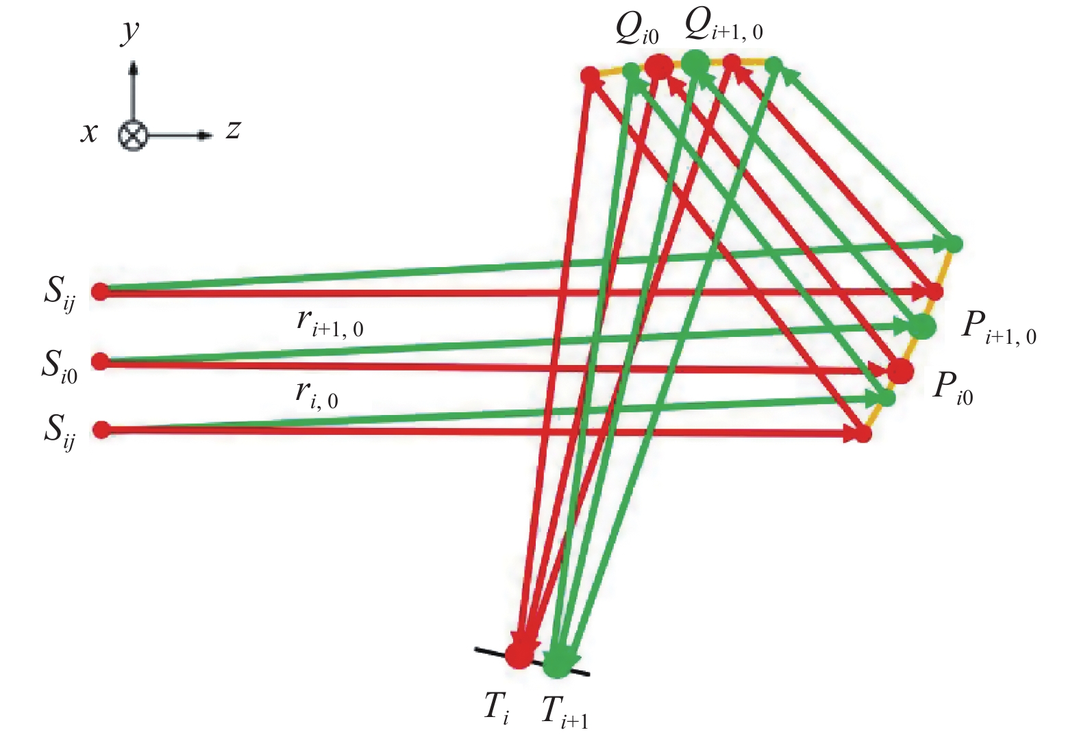
如图3(a)所示,选取M个视场,在极坐标下对每个视场的光瞳分别均匀采样K个数据点,对应该视场下K条特征光线;在采样过程中,为了确保采样均匀,在光瞳内采样点个数随着半径的增大而增加。定义特征光线为入射至自由曲面反射镜Ω的平行光
${r}_{ij}\left(i=1,\mathrm{ }\mathrm{ }\cdots ,M;j=0,\mathrm{ }1,\mathrm{ }2,\mathrm{ }\cdots ,K-1\right)$ 以及经自由曲面反射镜的反射光线${r}_{ij}^{\mathrm{\text{'}}}\left(i=1,\mathrm{ }2,\mathrm{ }\cdots ,M;j=0,\mathrm{ }1,\mathrm{ }\mathrm{ }\cdots , K-1\right)$ ,定义特征数据点为特征光线与自由曲面反射镜Ω的交点${P}_{ij}\left(i=1,\mathrm{ }2,\mathrm{ }\cdots ,M;j=0,\mathrm{ }1,\mathrm{ }\mathrm{ }\cdots ,K-1\right)$ 。
图 3 (a) 定义光瞳上的采样点;(b) 定义特征光线和特征光线的起点
Figure 3. (a) Define the data points on pupil; (b) Define the feature rays and the starting points of feature rays
如图3(b)所示,对于每个采样视场i,波前平面经过光瞳中心
$ {S}_{i0} $ ,并与主光线$ {r}_{i0} $ 垂直,因此该视场下的所有特征光线与波前平面相交且垂直,交点${S}_{ij}(i=1,\mathrm{ }2,\mathrm{ }\cdots ,M;j=0,\mathrm{ }1,\mathrm{ }\mathrm{ }\cdots ,K-1)$ 定义为特征光线的起点。定义
${T}_{i}(i=1,\mathrm{ }2,\mathrm{ }\cdots ,M)$ 为各视场特征光线在像面上的理想像点,根据物像关系和像面位置计算理想像点的位置。对于来自第i个视场$ \left({\omega }_{x},{\omega }_{y}\right) $ 的特征光线,$ {T}_{i,ideal} $ 的全局坐标为:$$ \begin{split} {T_{i,ideal}} =& \left[ \begin{gathered} {T_{i,ideal,x}} \\ {T_{i,ideal,y}} \\ {T_{i,ideal,z}} \\ \end{gathered} \right] =\\ & \left[ {\begin{array}{*{20}{c}} 1&0 \\ 0&{\cos \alpha } \\ 0&{ - \sin \alpha } \end{array}} \right]\left[ {\begin{array}{*{20}{c}} {f\tan {\omega _x}} \\ {f\tan {\omega _y}} \end{array}} \right] + \left[ {\begin{array}{*{20}{c}} {{x_0}} \\ {{y_0}} \\ {{z_0}} \end{array}} \right] \\ \end{split} $$ (1) 式中:
$ f $ 为系统的焦距;$ \left({x}_{0},{y}_{0}{,z}_{0}\right) $ 是像面中心的坐标,即零视场$ \left(0°,\mathrm{ }0°\right) $ 的理想像点坐标,根据无遮拦条件来确定其坐标;$ \mathrm{\alpha } $ 为像面关于x轴的倾斜角度。(2)求解未知自由曲面上的特征数据点
根据特征光线的起点
$ {S}_{ij} $ 、自由曲面反射镜Ω的已知特征数据点$ {P}_{10} $ 和理想目标点$ {T}_{1} $ ,建立相邻两个采样视场之间的迭代关系,计算自由曲面反射镜Ω的所有特征数据点。如图4(a)、图5所示,在第1个采样视场中,定义从出瞳中心
$ {S}_{10} $ 发出的主光线$ {r}_{10} $ 为参考光线,定义第1个采样视场下的特征数据点$ {P}_{1 j} $ 构成的曲面为自由曲面${\varOmega }_{1}$ ;参考光线$ {r}_{10} $ 与自由曲面${\varOmega }_{1}$ 的交点作为参考点$ {P}_{10} $ ,自由曲面${\varOmega }_{1}$ 的位置根据系统尺寸确定;参考光线$ {r}_{10} $ 在参考点$ {P}_{10} $ 处反射后到达理想目标点$ {T}_{1} $ ;计算第1个采样视场下经过自由曲面${\varOmega }_{1}$ 反射的光程:
图 4 (a) 自由曲面单反射面光学系统YOZ平面示意图;(b) 全视场下自由曲面构建示意图
Figure 4. (a) Layout of freeform surface single-mirror optical system in YOZ plane; (b) Diagram of freeform surface construction in full FOV
$$ OP = n\left| {{S_{10}}{P_{10}}} \right| + n\left| {{P_{10}}{T_1}} \right| $$ (2) 式中:
$ n $ 为介质的折射率,系统在空气中,则$ n=1 $ ;$ {T}_{1} $ 为理想目标点,通过物像关系求解。根据马吕斯定律,该采样视场中的所有特征光线具有相同的光程,在该视场中求得K个特征数据点${P}_{1 j}(j=\mathrm{0,1},\mathrm{ }\cdots ,K-1)$ ,它满足以下条件:$$ n\left|{S}_{1j}{P}_{1j}\right|+n\left|{P}_{1j}{T}_{1}\right|=OP $$ (3) 将第1个视场下的所有特征数据点
$ {P}_{1 j} $ 拟合成用多项式表征的自由曲面${\varOmega }_{1}$ ;在得到前
$ i\left(1\leqslant i \leqslant M-1\right) $ 个视场下的自由曲面$\sum _{1}^{i}\varOmega$ 后,在第$ i+1 $ 个采样视场中,将从出瞳中心$ {S}_{i+\mathrm{1,0}} $ 发出的主光线$ {r}_{i+\mathrm{1,0}} $ 作为参考光线,定义第$ i+1 $ 个采样视场下的特征数据点$ {P}_{i+1,j} $ 构成的曲面为自由曲面${\varOmega }_{1+1}$ ;参考光线$ {r}_{i+\mathrm{1,0}} $ 与已知自由曲面$\sum _{1}^{i}\varOmega$ 的交点作为参考点$ {P}_{i+\mathrm{1,0}} $ ,参考光线$ {r}_{i+\mathrm{1,0}} $ 在参考点$ {P}_{i+\mathrm{1,0}} $ 处反射后到达理想目标点$ {T}_{i+1} $ ;计算第 i + 1 个视场参考光线的光程,根据马吕斯定律,求解第$ i+1 $ 个采样视场下自由曲面${\varOmega }_{1+1}$ 上特征数据点$ {P}_{i+1,j} $ 。将前
$ i+1\left(1\leqslant i \leqslant M-1\right) $ 个视场下的所有特征数据点${P}_{1 j}\mathrm{、}{P}_{2 j}\cdots {P}_{i+1,j}$ 拟合成用多项式表征的自由曲面$\sum _{1}^{i+1}\mathrm{\varOmega }$ ;重复上述步骤构建前$ i $ 个视场和第$ i+1 $ 个视场下的自由曲面的迭代关系,分别得到M个视场下自由曲面Ω的特征数据点坐标${P}_{1 j}\mathrm{、}{P}_{2 j}\cdots {P}_{i,j}\cdots {P}_{M,j}$ 。(3)将特征数据点拟合成自由曲面
用最小二乘法将自由曲面反射镜Ω的所有特征数据点拟合成用泽尼克多项式(公式(4))表征的自由曲面,得到离轴头戴显示光学系统初始结构;利用评价函数对拟合的多项式系数进行优化,确定所述多项式的最优拟合系数,生成所需的自由曲面反射镜,得到离轴头戴显示光学系统最终结构。
$$ \begin{split} \varphi (x,y) =& \sum\limits_{j = 1}^n {{k_j}{z_j}(x,y)} = {k_1}{z_1}(x,y) + \\ & {k_2}{z_2}(x,y) + \cdots + {k_n}{z_n}(x,y) \\ \end{split} $$ (4) 上述计算方法可用于多个自由曲面反射镜的计算。当系统中存在N个待求自由曲面反射镜时,首先将自由曲面反射镜F1作为第一个待求自由曲面,将其他N−1个反射镜设为已知球面;根据费马原理和马吕斯定律,以及特征光线的起点、相邻两个采样视场下自由曲面反射镜F1的特征数据点和理想目标点,建立相邻两个采样视场之间的迭代关系,在全视场范围内计算第1个自由曲面反射镜F1的特征数据点,将该自由曲面反射镜F1的所有特征数据点进行多项式拟合,得到多项式表征的所述自由曲面反射镜F1。 将自由曲面反射镜F2作为第2个待求自由曲面,保持其他N−2个初始球面反射镜及自由曲面反射镜F1不变,计算得到自由曲面反射镜F2。重复上述步骤,完成N个待求自由曲面反射镜的计算。
以双反射面自由曲面系统为例,如图5所示,P和Q分别在自由曲面反射镜F1和F2上。将自由曲面反射镜F1作为第一个待求自由曲面,F2设为已知球面。根据费马原理,对于任意一个视场,
$ {Q}_{i0} $ 在球面F2上,并使$ {P}_{i0} $ 至理想目标点$ {T}_{i} $ 的距离最近:
图 5 自由曲面双反射面光学系统YOZ平面示意图
Figure 5. Layout of freeform surface two-mirror optical system in YOZ plane
$$ n\left| {{P_{i0}}{Q_{i0}}} \right| + n\left| {{Q_{i0}}{T_i}} \right| = \min $$ (5) 计算参考光线的光程
$ OP $ :$$ OP = n\left| {{S_{i0}}{P_{i0}}} \right| + n\left| {{P_{i0}}{Q_{i0}}} \right| + n\left| {{Q_{i0}}{T_i}} \right| $$ (6) 根据马吕斯定律,该采样视场中的所有特征光线具有相同的光程,在该视场中找到其他K−1个特征数据点
$ {P}_{ij}(j=1,\mathrm{ }2,\mathrm{ }\cdots ,K-1) $ ,它满足以下条件:$$ n\left| {{S_{ij}}{P_{ij}}} \right| + n\left| {{P_{ij}}{Q_{ij}}} \right| + n\left| {{Q_{ij}}{T_i}} \right| = OP $$ (7) -
对于大多数头戴显示系统,全视场角通常约为20°~40°[13-15];而太大的视场角可能会引起视觉疲劳,因为眼睛需要扫描较大角度。另外对于单反射面头戴显示系统,当视场角过大时,图像源必须设置为曲面才能满足要求,文中设计采用平面微显示器作为图像源,因此选择中等要求的24°对角视场,用上述方法进行设计,设计指标如表1所示。X方向视场角为19.12°,Y方向视场角为14.4°。
表 1 自由曲面离轴单反头戴显示光学系统设计指标
Table 1. Specifications of freeform surface off-axis single-mirror HMD optical system design
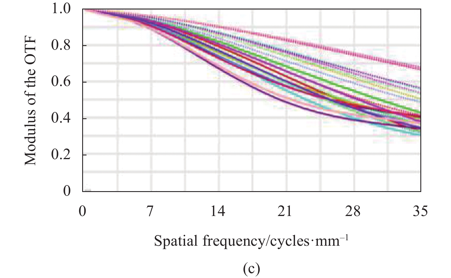
Parameter Specifications Full field of view/(°) 24(19.12×14.4) Exit pupil diameter/mm 3 Effective focal length/mm 14.25 Pixel size/μm 14.1 Distance of exit pupil/mm >15 Spectral range Visible light band Image quality >30%@35 lp/mm Distortion <5% Size of the micro display 0.25 in(6.35 mm) 对165个视场进行采样,分别为:(0°, 0°),(0°, ±1°),···,(0°, ±6°),(0°, ±7.2°); (1°, 0°),(1°, ±1°),···,(1°, ±6°),(1°, ±7.2°); ···(9°, 0°),(9°, ±1°),···,(9°, ±6°),(9°, ±7.2°); (9.56°, 0°),(9.56°, ±1°),···,(9.56°, ±6°),(9.56°, ±7.2°)。除边缘视场外,其他视场按1°间隔进行采样。每个视场选取63条特征光线,共选取10395条不同视场不同孔径位置的特征光线。按前述的设计方法求解全视场的自由曲面特征数据点,并将其拟合成用泽尼克多项式表征的自由曲面,自由曲面矢高如图6(a)所示,拟合系数如表2所示。在光学软件中构建自由曲面头戴显示光学系统初始结构,如图6(b)所示。图6(c)为初始结构的调制传递函数(MTF)图。
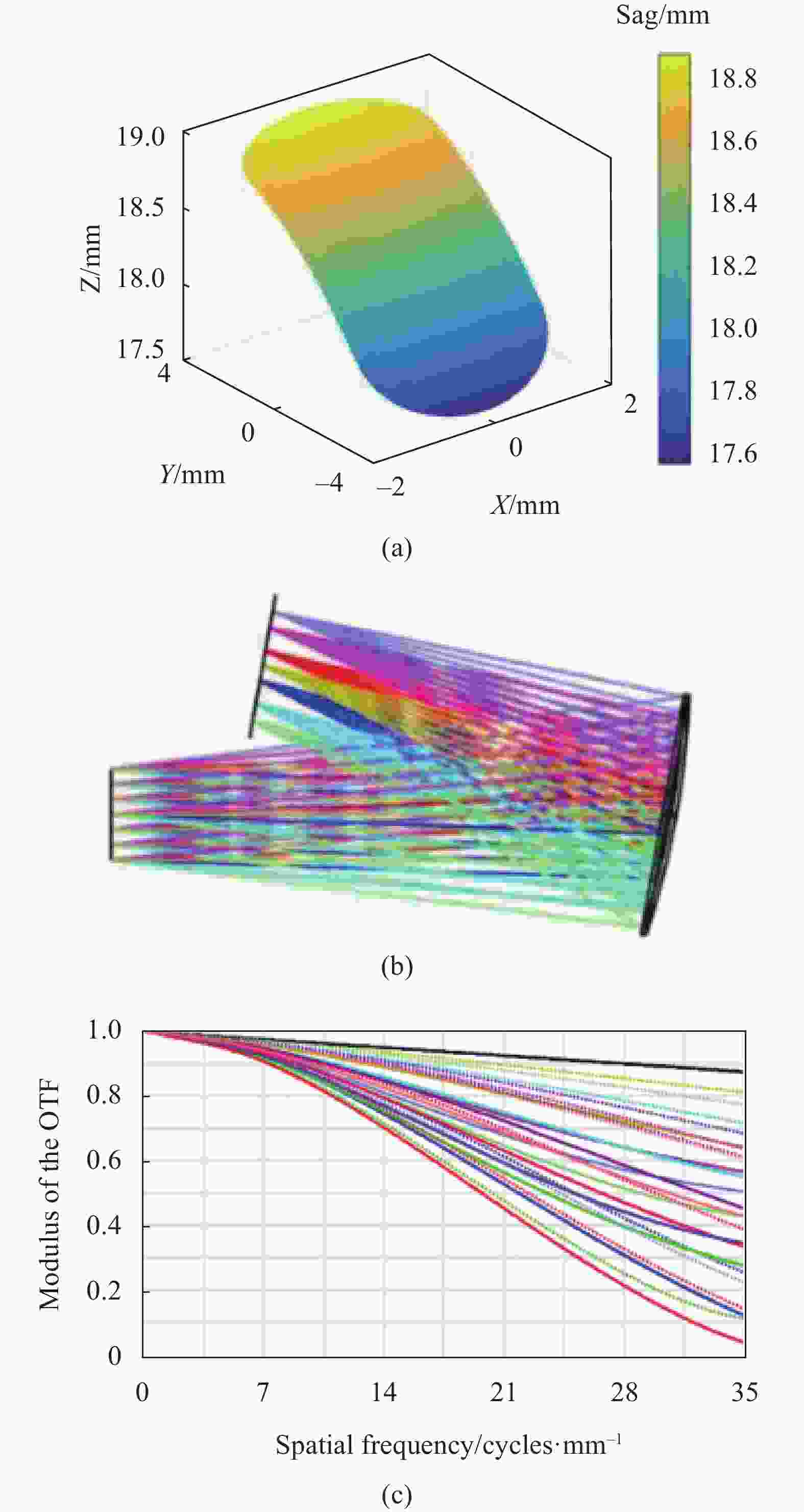
图 6 (a) 拟合得到的自由曲面矢高图;(b) 光学系统光路图;(c) 光学系统的调制传递函数曲线
Figure 6. (a) Sag map of freeform surface fitted; (b) Layout of the optical system; (c) MTF curves of the optical system
表 2 自由曲面反射镜的泽尼克多项式系数
Table 2. Zernike polynomial coefficients of freeform surface mirror
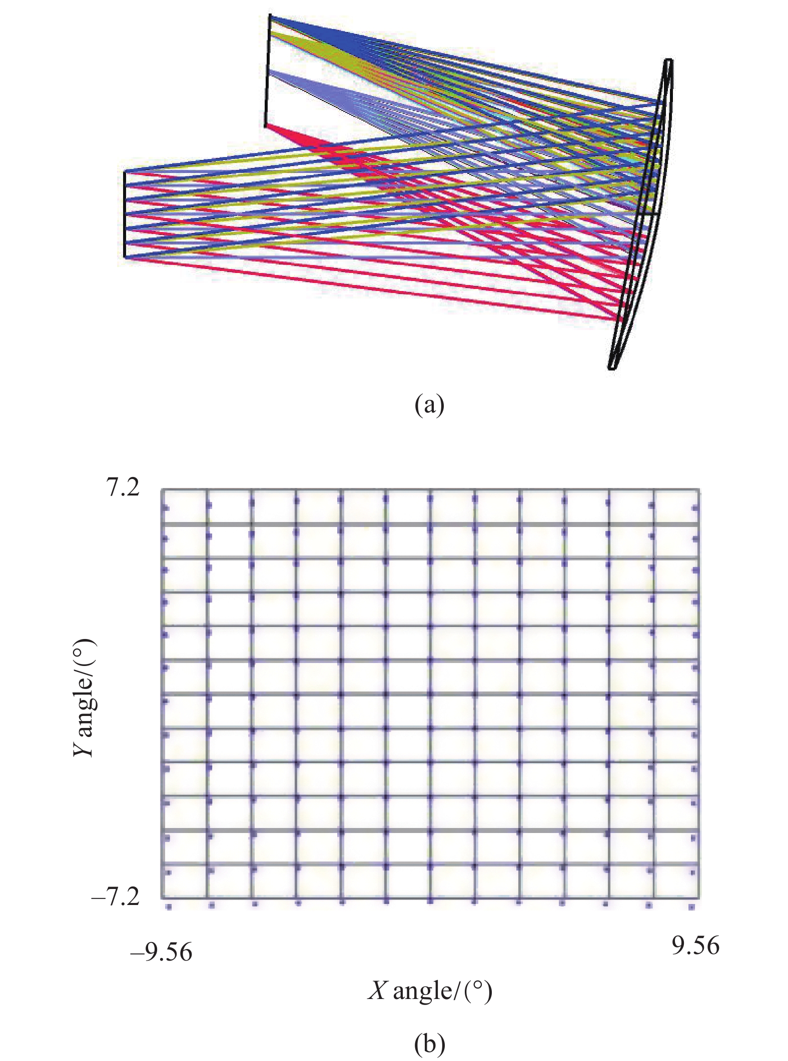
Polynomial $ {Z}_{i}(x,y) $ Polynomial coefficients $ {C}_{j} $ $ {Z}_{1} $ 1 $ {C}_{1} $ 18.472 $ {Z}_{2} $ 2$x$ $ {C}_{2} $ 0 ${{Z} }_{3}$ 2$ {y} $ $ {{C}}_{3} $ $ 9.011\times {10}^{-2} $ ${{Z} }_{4}$ $\sqrt{3}\left[2\left({{x} }^{2}+{{y} }^{2}\right)-1\right]$ ${{C} }_{4}$ $ -5.269\times {10}^{-3} $ ${{Z} }_{5}$ $2\sqrt{6}{x}{y}$ ${{C} }_{5}$ 0 ${{Z} }_{6}$ $\sqrt{6}\left({{x} }^{2}-{{y} }^{2}\right)$ ${{C} }_{6}$ $ 1.499\times {10}^{-4} $ ${{Z} }_{7}$ $ \sqrt{8}\left[3\left({{x}}^{2}+{{y}}^{2}\right)-2\right]{y} $ $ {{C}}_{7} $ $ 1.149\times {10}^{-5} $ ${{Z} }_{8}$ $ \sqrt{8}\left[3\left({{x}}^{2}+{{y}}^{2}\right)-2\right]{x} $ $ {{C}}_{8} $ 0 $ {{Z}}_{9} $ $ \sqrt{8}\left(3{{x}}^{2}-{{y}}^{2}\right){y} $ $ {{C}}_{9} $ $ 1.748\times {10}^{-6} $ $ {{Z}}_{10} $ $ \sqrt{8}\left({{x}}^{2}-{3{y}}^{2}\right){x} $ $ {{C}}_{10} $ 0 $ {{Z}}_{11} $ $ \sqrt{5}\left[6{\left({{x}}^{2}+{{y}}^{2}\right)}^{2}-6\left({{x}}^{2}+{{y}}^{2}\right)+1\right] $ $ {{C}}_{11} $ $ -6.282\times {10}^{-7} $ $ {{Z}}_{12} $ $ \sqrt{10}\left({{x}}^{2}-{{y}}^{2}\right)\left[4\left({{x}}^{2}+{{y}}^{2}\right)-3\right] $ $ {{C}}_{12} $ $ 3.439\times {10}^{-8} $ $ {{Z}}_{13} $ $ 2\sqrt{10}\left[4\left({{x}}^{2}+{{y}}^{2}\right)-3\right]{x}{y} $ $ {{C}}_{13} $ 0 $ {{Z}}_{14} $ $ \sqrt{10}\left({{x}}^{4}-{6{x}}^{2}{{y}}^{2}+{{y}}^{4}\right) $ $ {{C}}_{14} $ $ -9.838\times {10}^{-7} $ $ {{Z}}_{15} $ $ 4\sqrt{10}\left({{x}}^{2}-{{y}}^{2}\right){x}{y} $ $ {{C}}_{15} $ 0 根据设计指标设置优化评价函数,用光学设计软件进一步优化,得到如图7(a)所示的最终结构。图7(b)为用三维直接设计方法设计得到的最终系统网格畸变图,最大畸变约为−4.69%。图7(c)为系统的MTF曲线,MTF在35 lp/mm时约为0.3。可以推断出,用基于马吕斯定律的自由曲面三维直接设计方法能够直接设计得到自由曲面单反射面头戴显示光学系统的初始结构,且该结构优化后光学性能满足要求。

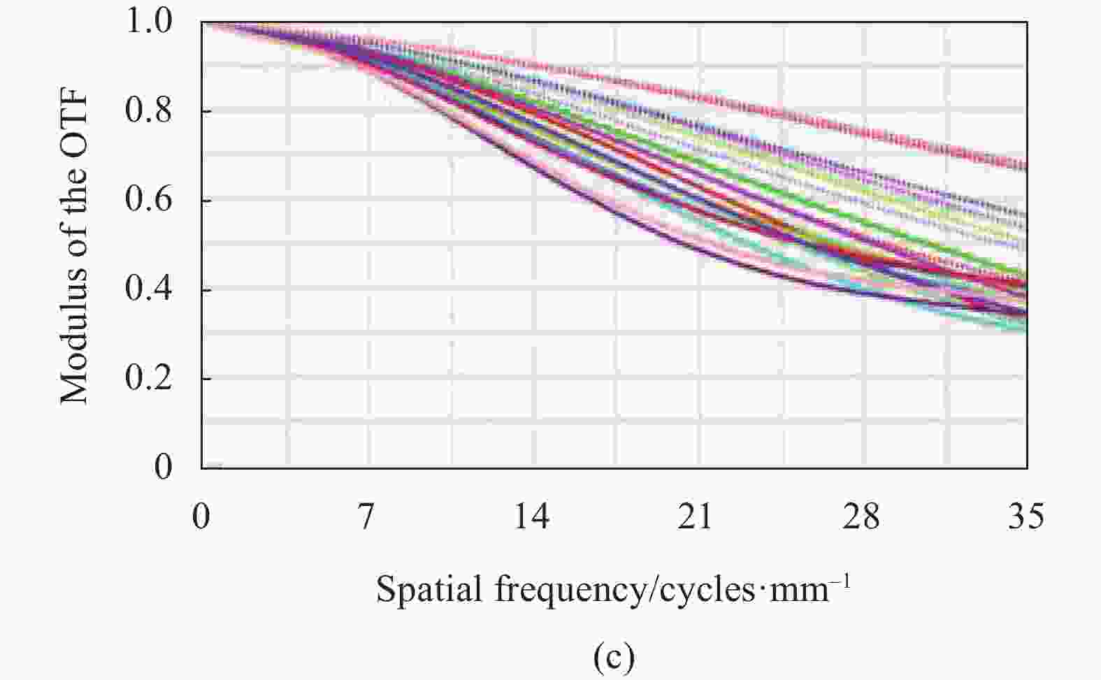
图 7 (a) 优化后的单反射面头戴显示光学系统光路图; (b) 网格畸变; (c) 光学系统MTF曲线
Figure 7. (a) Layout of the single-mirror HMD optical system after optimi-zation; (b) Grid distortion; (c) MTF curves of the optical system
-
用上述方法设计了一个双反射面头戴显示系统,设计指标如表3所示。放松状态下的眼睛的瞳孔直径约为2~3 mm,确定出瞳直径为8 mm,全视场角约为28°,相应X方向的视场角为23°,Y方向的视场角为16°。
表 3 自由曲面双反射头戴显示光学系统设计指标
Table 3. Specifications of freeform surface two-mirror HMD optical system design
Parameters Specifications Micro display Micro display OLED Size 0.61 in (12.36 mm×9.36 mm) Resolution/pixel 800×600 Pixel size/μm 15 Head-mounted display system Structure Off-axis two-reflective system Exit pupil diameter/mm 8 F/# 4 Distance of exit pupil/mm >30 Full field of view/(°) 28(23×16) Performance MTF >0.4@30 lp/mm,with a 4 mm exit pupil Maximum distortion <5% 按照第1节的设计流程,设初始结构的两个反射镜都为球面,且曲率半径相等。根据焦距
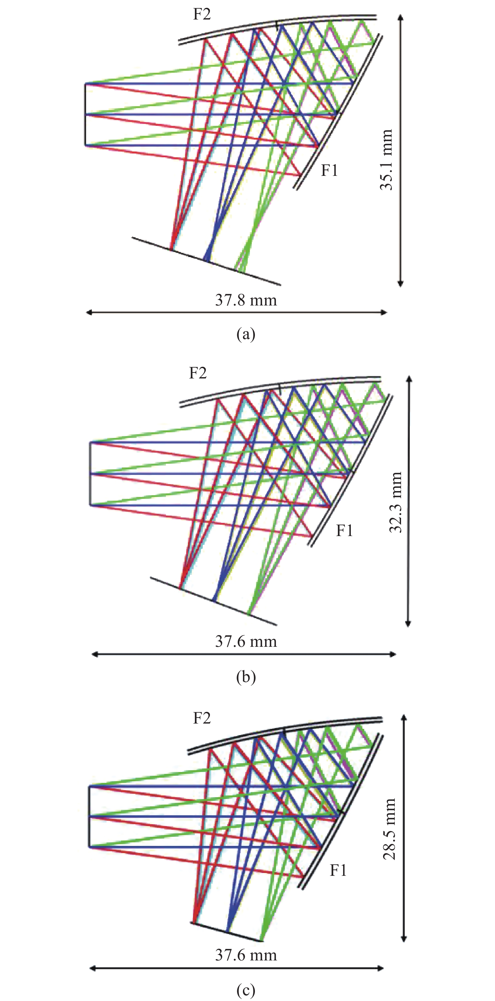
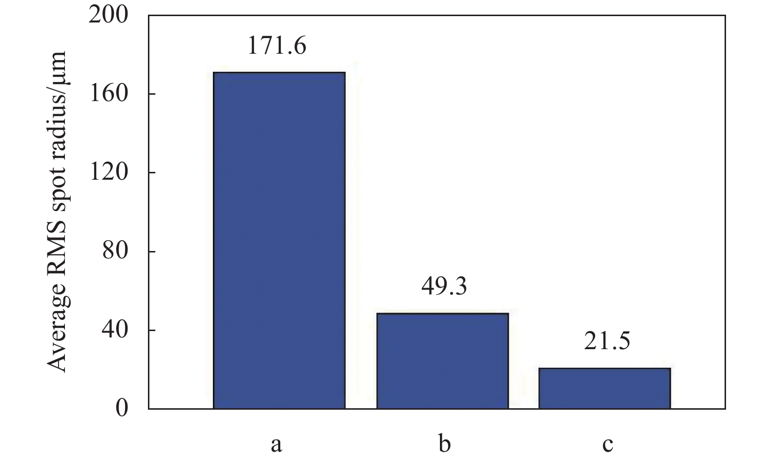
$ {f}{{{'}}}=32\; \mathrm{m}\mathrm{m} $ ,球面之间的空气间隔$ d=-8\; \mathrm{m}\mathrm{m} $ ,以及公式(8)可计算两个球面的曲率半径为$ {R}_{1}=-120\; \mathrm{m}\mathrm{m} $ ,$ {R}_{2}=120\; \mathrm{m}\mathrm{m} $ 。$$ {f'} = - \frac{{f_1'f_2'}}{D} = \frac{{n{R_1}{R_2}}}{{(n - 1)[n({R_2} - {R_1}) + (n - 1)d]}} $$ (8) 设计结果如图8所示。图8(a)中,两个反射面均为球面的系统作为初始结构;将球面F2固定,计算自由曲面F1,如图8(b)所示;再将已知的自由曲面F1固定,计算自由曲面F2,得到F1和F2均为自由曲面的光学系统,如图8(c)所示。三种系统各视场平均 RMS 光斑半径的对比如图9所示。F1, F2均为球面时,平均 RMS 光斑半径为171.6 μm,此时系统存在较大的场曲和像散;F1为自由曲面时,平均 RMS 光斑半径减小至49.3 μm,这是由于自由曲面F1校正了部分像散;F1, F2均为自由曲面时,成像质量进一步改善,平均 RMS 光斑半径减小至21.5 μm。F1, F2均为自由曲面的系统,可以作为初始结构进一步优化。

图 8 自由曲面双反射面头戴显示系统光路图。 (a) F1, F2均为球面;(b) F1为自由曲面;(c) F1, F2均为自由曲面
Figure 8. Layouts of freeform surface two-mirror HMD system. (a) Both F1 and F2 are spheres; (b) F1 is a freeform surface; (c) Both F1 and F2 are freeform surfaces

图 9 三种光学系统平均 RMS 光斑半径对比
Figure 9. Comparison of the average RMS spot diameter between three optical systems
将图8(c)的自由曲面初始结构进行优化,得到如图10(a)所示的最终光学系统。图10(b)和10(c)显示,双反射面头戴显示系统的最大畸变约为−4.63%,MTF在33 lp/mm时大于0.4。由此可见,用三维直接设计方法设计的自由曲面双反射面头戴显示光学系统作为一个良好的初始结构,优化后其光学性能满足要求。

图 10 (a) 优化后的双反射面头戴显示光学系统光路图;(b) 网格畸变;(c) 光学系统MTF曲线
Figure 10. (a) Layout of the two-mirror HMD optical system after optimi-zation; (b) Grid distortion; (c) MTF curves of optical system
-
对单反射面头戴显示系统和双反射面头戴显示系统分别进行公差敏感度分析和1000次蒙特卡洛分析,公差项包括镜面加工公差和系统装调公差。单反射面头戴显示系统中,对成像质量影响最大的公差项为自由曲面M1的X方向偏心;双反射面头戴显示系统中,对成像质量影响最大的公差项为自由曲面F1的Y方向偏心和自由曲面F2的Y方向偏心。
通过收紧最敏感公差项,得到如表4和表5所示的公差分配以及表6和表7所示的公差分析结果。其中,当自由曲面M1、F1和F2系数公差为±0.05时,引起面型误差PV变化在1/4 λ范围内。公差分析表明,引入公差后单反射面头戴显示系统全视场MTF均大于0.3,相对于理论值的变化量均小于5.1%;引入公差后双反射面头戴显示系统边缘视场MTF大于0.35,相对于理论值的变化量为12.4%;其他采样视场的MTF均大于0.35,变化量均在10%以下。
表 4 自由曲面单反射面头戴显示光学系统公差分配
Table 4. Tolerance data for freeform surface single-mirror HMD optical system
Manufacture tolerance Alignment tolerance Shape error PV/λ Air thickness
/mmDecenter X
/mmDecenter Y
/mmTilt X/(°) Tilt Y/(°) Tilt Z/(°) M1 1/4 - ±0.2 ±0.2 ±0.2 ±0.2 ±0.2 表 5 自由曲面双反射面头戴显示光学系统公差分配
Table 5. Tolerance data for freeform surface two-mirror HMD optical system
Manufacture tolerance Alignment tolerance Shape error PV/λ Air thickness
/mmDecenter X
/mmDecenter Y
/mmTilt X/(°) Tilt Y/(°) Tilt Z/(°) F1 1/4 ±0.2 ±0.2 ±0.15 ±0.2 ±0.2 ±0.2 F2 1/4 ±0.2 ±0.2 ±0.1 ±0.2 ±0.2 ±0.25 表 6 自由曲面单反射面头戴显示光学系统公差分析结果
Table 6. Tolerance analysis of freeform surface single-mirror HMD optical system
Field X field
/(°)Y field
/(°)Theoretical MTF avg Toleranced MTF avg MTF change 1 0 0 0.378 0.368 2.7% 2 0 7.2 0.416 0.405 2.6% 3 0 −7.2 0.495 0.482 2.6% 4 6.76 0 0.407 0.401 1.5% 5 6.76 7.2 0.356 0.338 5.1% 6 6.76 −7.2 0.535 0.530 0.9% 7 9.56 0 0.455 0.438 3.7% 8 9.56 7.2 0.328 0.315 3.9% 9 9.56 −7.2 0.532 0.528 0.7% 表 7 自由曲面双反射面头戴显示光学系统公差分析结果
Table 7. Tolerance analysis for freeform surface two-mirror HMD optical system
Field X field
/(°)Y field
/(°)Theoretical MTF avg Toleranced MTF avg MTF change 1 0 0 0.516 0.478 7.4% 2 0 8 0.560 0.506 9.6% 3 0 −8 0.574 0.533 7.1% 4 11.5 0 0.453 0.397 12.4% 5 11.5 8 0.579 0.539 6.9% 6 11.5 −8 0.407 0.370 9.1% 7 5.75 0 0.569 0.526 7.6% 8 5.75 8 0.738 0.687 6.9% 9 5.75 −8 0.505 0.462 8.5% -
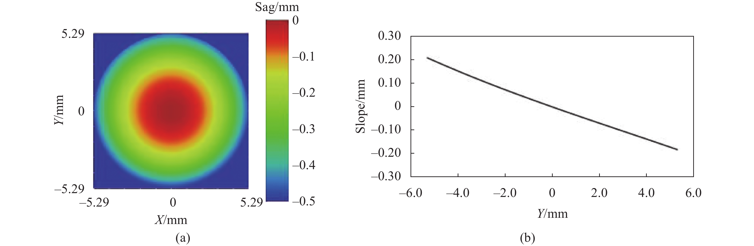
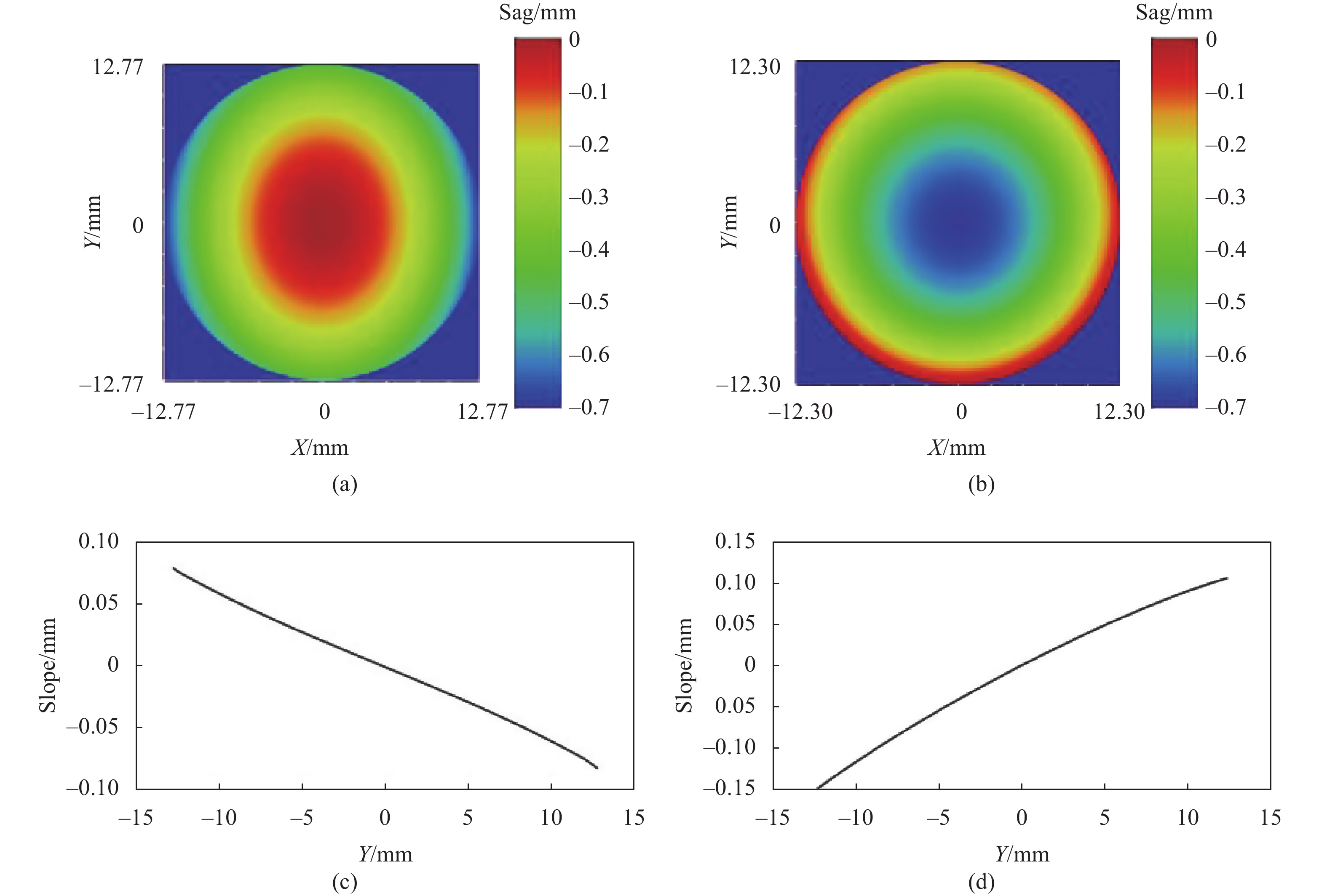
对自由曲面的面型加工性进行分析,图11为单反射面头戴显示系统自由曲面矢高图和有效通光口径内斜率图,即矢高相对于Y轴的变化率。图12(a)、(b)分别为双反射面头戴显示系统自由曲面F1、F2矢高图。图12(c)、(d)分别为F1、F2在有效通光口径内斜率图。由图可知,矢高在有效通光口径内均不存在突变和拐点,整体变化趋势较为平缓,有利于自由曲面的加工。

图 11 自由曲面单反射面头戴显示系统矢高图和斜率图。 (a) M1矢高图;(b) M1斜率图
Figure 11. Surface sag and slope diagram of freeform surface single-mirror HMD system. (a) Surface sag diagram of M1; (b) Surface slope diagram of M1

图 12 自由曲面双反射面头戴显示系统矢高图和斜率图。 (a) F1矢高图;(b) F2矢高图;(c) F1斜率图;(d) F2斜率图
Figure 12. Surface sag and slope of diagram of freeform surface two-mirror HMD system. (a) Surface sag diagram of F1; (b) Surface sag diagram of F2; (c) Surface slope diagram of F1; (d) Surface slope diagram of F2
-
针对现有自由曲面设计方法不能直接设计全视场全孔径自由曲面反射镜的问题,提出了基于马吕斯定律的自由曲面三维直接设计方法。该方法简化了计算流程,比现有的自由曲面直接设计方法更简单,计算效率更高。用所提出的方法设计了单/双反射面头戴显示系统,成像质量满足使用要求。对该系统进行公差分析,在合理的公差分配下,单/双反射面头戴显示系统全视场MTF变化量分别小于5.1%和12.4%。该方法也可以有效地应用到其他自由曲面反射镜的系统中,比如超薄投影系统、抬头显示系统等。但是由于视场采样点较少和拟合精度不够等原因,初始结构仍然存在一定的像差,因此,还需要进一步研究迭代方法,以提高初始系统的像质。
Design method of freeform surface for off-axis reflective head-mounted display optical system
-
摘要: 为克服现有离轴头戴显示光学系统设计方法不能直接设计全视场全孔径自由曲面反射镜的问题,提出了基于马吕斯定律的自由曲面三维直接设计方法。首先根据马吕斯定律求解自由曲面在全视场和全孔径范围内的所有特征数据点,然后将特征数据点拟合成用多项式表征的自由曲面,直接获得成像质量良好的自由曲面离轴系统初始结构,最后利用评价函数对拟合的多项式系数进行优化,确定最佳拟合系数,生成所需的自由曲面反射镜,得到离轴头戴显示光学系统最终结构。该方法简化了设计流程,计算效率高。基于提出的方法分别设计了单反射面和双反射面的头戴显示光学系统,单反射面系统的出瞳直径为3 mm,视场角19.12°×14.4°;双反射面系统的出瞳直径为8 mm,视场角23°×16°。设计结果表明,用该方法设计的单/双反射面头戴显示系统,其成像质量良好,系统结构紧凑。公差分析表明,引入公差后单/双反射面头戴显示系统最终可实现全视场调制传递函数(MTF)大于0.3 lp/mm和0.35 lp/mm。Abstract: In order to overcome the shortcomings of the existing direct design method of freeform surface and the large amount of calculation, according to the structural characteristics of the off-axis display system, a three-dimensional direct design method of freeform surface based on Marius's law is proposed. First, according to Marius's law, all the characteristic data points of the freeform surface are solved in the full field of view and the full aperture. Then the characteristic data points are fitted into a freeform surface characterized by polynomials, and the initial structure of freeform off-axis system with good imaging quality is obtained directly. Finally, the polynomial coefficient is optimized with the merit function and the best fitting coefficient is determined. The required freeform surface mirror is generated and the final structure of the off-axis head-mounted display optical system is obtained. This method simplifies the design process and has high calculation efficiency. Based on the proposed method, a single-mirror head-mounted display optical system and a two-mirror head-mounted display optical system are designed with an entrance pupil diameter of 3 mm, a field angle of 19.12°×14.4° and an entrance pupil diameter of 8 mm, a field angle of 23°×16°, respectively. The design results show that single/two-mirror head-mounted display system designed by proposed method has good imaging quality and compact system structure. Tolerance analysis shows that the single/two head-mounted display system can finally achieve MTF greater than 0.3 lp/mm and 0.35 lp/mm in full field of view after introducing tolerances.
-
Key words:
- optical design /
- freeform surface /
- Marius's law /
- off-axis display system
-
图 1 基于马吕斯定律的三维直接设计方法示意图
Figure 1. Diagram of three-dimensional direct design method based on Marius's law
图 2 基于马吕斯定律的三维直接设计方法流程图
Figure 2. Flow chart of three-dimensional direct design method based on Marius's law
图 3 (a) 定义光瞳上的采样点;(b) 定义特征光线和特征光线的起点
Figure 3. (a) Define the data points on pupil; (b) Define the feature rays and the starting points of feature rays
图 4 (a) 自由曲面单反射面光学系统YOZ平面示意图;(b) 全视场下自由曲面构建示意图
Figure 4. (a) Layout of freeform surface single-mirror optical system in YOZ plane; (b) Diagram of freeform surface construction in full FOV
图 5 自由曲面双反射面光学系统YOZ平面示意图
Figure 5. Layout of freeform surface two-mirror optical system in YOZ plane
图 6 (a) 拟合得到的自由曲面矢高图;(b) 光学系统光路图;(c) 光学系统的调制传递函数曲线
Figure 6. (a) Sag map of freeform surface fitted; (b) Layout of the optical system; (c) MTF curves of the optical system
7 (a) 优化后的单反射面头戴显示光学系统光路图; (b) 网格畸变; (c) 光学系统MTF曲线
7. (a) Layout of the single-mirror HMD optical system after optimi-zation; (b) Grid distortion; (c) MTF curves of the optical system
图 8 自由曲面双反射面头戴显示系统光路图。 (a) F1, F2均为球面;(b) F1为自由曲面;(c) F1, F2均为自由曲面
Figure 8. Layouts of freeform surface two-mirror HMD system. (a) Both F1 and F2 are spheres; (b) F1 is a freeform surface; (c) Both F1 and F2 are freeform surfaces
图 9 三种光学系统平均 RMS 光斑半径对比
Figure 9. Comparison of the average RMS spot diameter between three optical systems
图 10 (a) 优化后的双反射面头戴显示光学系统光路图;(b) 网格畸变;(c) 光学系统MTF曲线
Figure 10. (a) Layout of the two-mirror HMD optical system after optimi-zation; (b) Grid distortion; (c) MTF curves of optical system
图 11 自由曲面单反射面头戴显示系统矢高图和斜率图。 (a) M1矢高图;(b) M1斜率图
Figure 11. Surface sag and slope diagram of freeform surface single-mirror HMD system. (a) Surface sag diagram of M1; (b) Surface slope diagram of M1
图 12 自由曲面双反射面头戴显示系统矢高图和斜率图。 (a) F1矢高图;(b) F2矢高图;(c) F1斜率图;(d) F2斜率图
Figure 12. Surface sag and slope of diagram of freeform surface two-mirror HMD system. (a) Surface sag diagram of F1; (b) Surface sag diagram of F2; (c) Surface slope diagram of F1; (d) Surface slope diagram of F2
表 1 自由曲面离轴单反头戴显示光学系统设计指标
Table 1. Specifications of freeform surface off-axis single-mirror HMD optical system design
Parameter Specifications Full field of view/(°) 24(19.12×14.4) Exit pupil diameter/mm 3 Effective focal length/mm 14.25 Pixel size/μm 14.1 Distance of exit pupil/mm >15 Spectral range Visible light band Image quality >30%@35 lp/mm Distortion <5% Size of the micro display 0.25 in(6.35 mm)  下载: 导出CSV
表 2 自由曲面反射镜的泽尼克多项式系数
Table 2. Zernike polynomial coefficients of freeform surface mirror
Polynomial $ {Z}_{i}(x,y) $ Polynomial coefficients $ {C}_{j} $ $ {Z}_{1} $ 1 $ {C}_{1} $ 18.472 $ {Z}_{2} $ 2 $x$ $ {C}_{2} $ 0 ${{Z} }_{3}$ 2 $ {y} $ $ {{C}}_{3} $ $ 9.011\times {10}^{-2} $ ${{Z} }_{4}$ $\sqrt{3}\left[2\left({{x} }^{2}+{{y} }^{2}\right)-1\right]$ ${{C} }_{4}$ $ -5.269\times {10}^{-3} $ ${{Z} }_{5}$ $2\sqrt{6}{x}{y}$ ${{C} }_{5}$ 0 ${{Z} }_{6}$ $\sqrt{6}\left({{x} }^{2}-{{y} }^{2}\right)$ ${{C} }_{6}$ $ 1.499\times {10}^{-4} $ ${{Z} }_{7}$ $ \sqrt{8}\left[3\left({{x}}^{2}+{{y}}^{2}\right)-2\right]{y} $ $ {{C}}_{7} $ $ 1.149\times {10}^{-5} $ ${{Z} }_{8}$ $ \sqrt{8}\left[3\left({{x}}^{2}+{{y}}^{2}\right)-2\right]{x} $ $ {{C}}_{8} $ 0 $ {{Z}}_{9} $ $ \sqrt{8}\left(3{{x}}^{2}-{{y}}^{2}\right){y} $ $ {{C}}_{9} $ $ 1.748\times {10}^{-6} $ $ {{Z}}_{10} $ $ \sqrt{8}\left({{x}}^{2}-{3{y}}^{2}\right){x} $ $ {{C}}_{10} $ 0 $ {{Z}}_{11} $ $ \sqrt{5}\left[6{\left({{x}}^{2}+{{y}}^{2}\right)}^{2}-6\left({{x}}^{2}+{{y}}^{2}\right)+1\right] $ $ {{C}}_{11} $ $ -6.282\times {10}^{-7} $ $ {{Z}}_{12} $ $ \sqrt{10}\left({{x}}^{2}-{{y}}^{2}\right)\left[4\left({{x}}^{2}+{{y}}^{2}\right)-3\right] $ $ {{C}}_{12} $ $ 3.439\times {10}^{-8} $ $ {{Z}}_{13} $ $ 2\sqrt{10}\left[4\left({{x}}^{2}+{{y}}^{2}\right)-3\right]{x}{y} $ $ {{C}}_{13} $ 0 $ {{Z}}_{14} $ $ \sqrt{10}\left({{x}}^{4}-{6{x}}^{2}{{y}}^{2}+{{y}}^{4}\right) $ $ {{C}}_{14} $ $ -9.838\times {10}^{-7} $ $ {{Z}}_{15} $ $ 4\sqrt{10}\left({{x}}^{2}-{{y}}^{2}\right){x}{y} $ $ {{C}}_{15} $ 0
下载: 导出CSV
表 3 自由曲面双反射头戴显示光学系统设计指标
Table 3. Specifications of freeform surface two-mirror HMD optical system design
Parameters Specifications Micro display Micro display OLED Size 0.61 in (12.36 mm×9.36 mm) Resolution/pixel 800×600 Pixel size/μm 15 Head-mounted display system Structure Off-axis two-reflective system Exit pupil diameter/mm 8 F/# 4 Distance of exit pupil/mm >30 Full field of view/(°) 28(23×16) Performance MTF >0.4@30 lp/mm,with a 4 mm exit pupil Maximum distortion <5%
下载: 导出CSV
表 4 自由曲面单反射面头戴显示光学系统公差分配
Table 4. Tolerance data for freeform surface single-mirror HMD optical system
Manufacture tolerance Alignment tolerance Shape error PV/λ Air thickness
/mmDecenter X
/mmDecenter Y
/mmTilt X/(°) Tilt Y/(°) Tilt Z/(°) M1 1/4 - ±0.2 ±0.2 ±0.2 ±0.2 ±0.2
下载: 导出CSV
表 5 自由曲面双反射面头戴显示光学系统公差分配
Table 5. Tolerance data for freeform surface two-mirror HMD optical system
Manufacture tolerance Alignment tolerance Shape error PV/λ Air thickness
/mmDecenter X
/mmDecenter Y
/mmTilt X/(°) Tilt Y/(°) Tilt Z/(°) F1 1/4 ±0.2 ±0.2 ±0.15 ±0.2 ±0.2 ±0.2 F2 1/4 ±0.2 ±0.2 ±0.1 ±0.2 ±0.2 ±0.25
下载: 导出CSV
表 6 自由曲面单反射面头戴显示光学系统公差分析结果
Table 6. Tolerance analysis of freeform surface single-mirror HMD optical system
Field X field
/(°)Y field
/(°)Theoretical MTF avg Toleranced MTF avg MTF change 1 0 0 0.378 0.368 2.7% 2 0 7.2 0.416 0.405 2.6% 3 0 −7.2 0.495 0.482 2.6% 4 6.76 0 0.407 0.401 1.5% 5 6.76 7.2 0.356 0.338 5.1% 6 6.76 −7.2 0.535 0.530 0.9% 7 9.56 0 0.455 0.438 3.7% 8 9.56 7.2 0.328 0.315 3.9% 9 9.56 −7.2 0.532 0.528 0.7%
下载: 导出CSV
表 7 自由曲面双反射面头戴显示光学系统公差分析结果
Table 7. Tolerance analysis for freeform surface two-mirror HMD optical system
Field X field
/(°)Y field
/(°)Theoretical MTF avg Toleranced MTF avg MTF change 1 0 0 0.516 0.478 7.4% 2 0 8 0.560 0.506 9.6% 3 0 −8 0.574 0.533 7.1% 4 11.5 0 0.453 0.397 12.4% 5 11.5 8 0.579 0.539 6.9% 6 11.5 −8 0.407 0.370 9.1% 7 5.75 0 0.569 0.526 7.6% 8 5.75 8 0.738 0.687 6.9% 9 5.75 −8 0.505 0.462 8.5%
下载: 导出CSV
-
[1] Zhang Nan, Chang Junlei, Li Qinglin, et al. High-stability opto-mechanical structure design of dual channel off-axis remote sensing camera [J]. Infrared and Laser Engineering, 2019, 48(4): 0418005. (in Chinese) doi: 10.3788/IRLA201948.0418005 [2] Wang J, Zhou Q, Chen J, et al. Design of a see-through off-axis head-mounted-display optical system with an ellipsoidal surface [J]. Current Optics and Photonics, 2018, 2(3): 280-285. [3] Nie Y, Mohedano R, Benítez P, et al. Multifield direct design method for ultrashort throw ratio projection optics with two tailored mirrors [J]. Applied Optics, 2016, 55(14): 3794-3800. doi: 10.1364/AO.55.003794 [4] Cheng D, Wang Y, Hua H, et al. Design of an optical see-through head-mounted display with a low f-number and large field of view using a freeform prism [J]. Applied Optics, 2009, 48(14): 2655-2668. doi: 10.1364/AO.48.002655 [5] Yang T, Cheng D, Wang Y, et al. Design method of non-symmetric imaging systems consisting of multiple flat phase elements [J]. Optics Express, 2018, 26(19): 25347-25363. doi: 10.1364/OE.26.025347 [6] Chen Bingxu, Liao Zhiyuan, Cao Chao, et al. Design of the freeform imaging system with large field of view and large relative aperture [J]. Infrared and Laser Engineering, 2020, 49(8): 20200005. (in Chinese) doi: 10.3788/IRLA20200005 [7] Pan J W, Che-Wen C, Huang K D, et al. Demonstration of a broad band spectral head-mounted display with freeform mirrors [J]. Optics Express, 2014, 22(11): 12785-12798. doi: 10.1364/OE.22.012785 [8] Liu J, Miñano J C, Benítez P, et al. Single optical surface imaging designs with unconstrained object to image mapping[C]//SPIE, 2012, 8550: 855011. [9] González-Acua R G, Chaparro-Romo H A, Gutiérrez-Vega J C. General formula to design a freeform singlet free of spherical aberration and astigmatism [J]. Applied Optics, 2019, 58(4): 1010-1015. doi: 10.1364/AO.58.001010 [10] 苏宙平. 一种离轴多反自由曲面光学系统初始结构的设计方法: 中国, CN110927964 A[P]. 2020-03-27. [11] Wu W, Wang H, Jin G, et al. Fast automatic design method for freeform imaging systems through system construction and correction [J]. Optics Letters, 2020, 45(18): 5140-5143. doi: 10.1364/OL.398924 [12] 张以谟. 应用光学[M]. 北京: 电子工业出版社, 2008. Zhang Y M. Applied Optics[M]. Beijing: Publishing House of Electronics Industry, 2008. (in Chinese) [13] Cakmakci O, Rolland J P. Head-worn displays: A review [J]. Journal of Display Technology, 2006, 2(3): 199-216. doi: 10.1109/JDT.2006.879846 [14] Cakmakci O, Rolland J P. Examples of HWD Architectures: Low-, Mid-, and Wide-field of View Designs[M]. Berlin: Springer-Verlag, 2016. [15] Kress B C. Optical Architectures For Augmented-, Virtual-, and Mixed-reality Headsets [M]. Bellingham: SPIE Press, 2020. -

 点击查看大图

计量
- 文章访问数: 181
- HTML全文浏览量: 71
- PDF下载量: 79
- 被引次数: 0


